Craftsman 316.791961 User manual
- Category
- Grass trimmers
- Type
- User manual

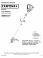
Operator's Manual
M
4=Cycle
GAS TRIMMER
Model No. 316.791961
INCREDI.PULL_'_
UNBELIEVABLE STARTING EA S E
,, SAFETY
oASSEMBLY
OPERATION
MAINTENANCE
PARTS LIST
ESPANOL, R 13
CAUTION: Before using this
product, read this manual and
follow all safety rules and
operating instructions.
Sears Brands Management Corporation, Hoffman Estates, IL 60179 U.S.A.
Visit our website: www.craftsman.com
P/N 769-06213 P00 11/10

CALiFORNiAPROPOSiTiON 65 WARNING
THE ENGINE EXHAUST FROM THiS PRODUCT CONTAINS CHEMICALS
KNOWN TO THE STATE OF CALiFORNiA TO CAUSE CANCER, BIRTH
DEFECTS OR OTHER REPRODUCTIVE HARM.
TABLE OF CONTENTS
Safety Rules ................................................. 2
Warranty .................................................... 4
Know Your Unit ............................................... 4
Assembly Instructions .......................................... 4
Oil and Fuel Information ........................................ 5
Starting/Stopping Instructions ................................... 6
Operating Instructions ......................................... 6
Maintenance and Repair Instructions .............................. 7
Cleaning and Storage .......................................... 9
Optional Accessory ............................................ 9
Troubleshooting Chart ........................................ 10
Specifications ............................................... 11
Parts List ................................................... 30
Service Numbers ..................................... Back Cover
SPARK ARRESTOR NOTE
NOTE: For users on U.S. Forest Land and in the states of California, Maine,
Oregon and Washington. All U.S. Forest Land and the state of California (Public
Resources Codes 4442 and 4443), Oregon and Washington require, by law that
certain internal combustion engines operated on forest brush and/or grass-covered
areas be equipped with a spark arrestor, maintained in effective working order, or
the engine be constructed, equipped and maintained for the prevention of fire.
Check with your state or local authorities for regulations pertaining to these
requirements. Failure to follow these requirements could subject you to liability or
a fine. This unit is factory equipped with a spark arrestor. If it requires
replacement, ask your LOCAL SERVICE DEALER to install the Accessory Part
#753=05245 Muffler Assembly.
All information, illustrations, and specifications in this manual are based on the
latest product information available at the time of printing. We reserve the right
to make changes at any time without notice.
The purpose of safety symbols is to attract your attention to possible dangers.
The safety symbols, and their explanations, deserve your careful attention and
understanding. The safety warnings do not by themselves eliminate any danger.
The instructions or warnings they give are not substitutes for proper accident
prevention measures.
SYMBOL MEANING
SAFETY ALERT: Indicates danger, warning or caution.
Attention is required in order to avoid serious personal injury.
May be used in conjunction with other symbols or pictographs.
DANGER: Failure to obey a safety warning will result in serious
injury to yourself or to others. Always follow the safety precautions
to reduce the risk of fire, electric shock and personal injury.
WARNING: Failure to obey a safety warning can result in
injury to yourself and others. Always follow the safety precautions
to reduce the risk of fire, electric shock and personal injury.
_IL CAUTION: Failure to obey a safety warning may result in
property damage or personal injury to yourself or to others.
Always follow the safety precautions to reduce the risk of fire,
electric shock and personal injury.
NOTE: Advises of information or instructions vital to the operation or
maintenance of the equipment.
NOTE= This Unit Can Use a Plug=in Power Start or Power Bit Start
Optional Accessory!
Please refer to the Plug-In Power Start or Power Bit Start operator's
manual for proper use of these features. (Items may be Sold
Separately! Please refer to page 9 of this manual for more information
about purchasing these accessories.)
Read the Operator's Manual and follow all warnings and safety instructions.
Failure to do so can result in serious injury to the operator and/or bystanders.
FOR QUESTIONS, CALL 1=800=4=MY=HOME®.
• iMPORTANT SAFETY iNSTRUCTiONS
READ ALL iNSTRUCTiONS BEFORE OPERATING
• Read the instructions carefully. Be familiar with the controls and proper use of
the unit.
Do not operate this unit when tired, ill,or under the influence of alcohol,
drugs, or medication.
Children and teens under the age of 15 must not use the unit, except for
teens guided by an adult.
All guards and safety attachments must be installed properly before operating
the unit.
Inspect the unit before use. Replace damaged parts. Check for fuel leaks.
Make sure all fasteners are in place and secure. Replace parts that are
cracked, chipped, or damaged in any way. Do not operate the unit with loose
or damaged parts.
Carefully inspect the area before starting the unit. Remove all debris and hard
or sharp objects such as glass, wire, etc.
Clear the area of children, bystanders, and pets. At a minimum, keep all
children, bystanders, and pets outside a 50 feet (15 m.) radius; there still may
be a risk to bystanders from thrown objects. Bystanders should be
encouraged to wear eye protection. Ifapproached, stop the unit immediately.
Use only Craftsman Hassle-Free TM XTRA QUIET Spiral Line as replacement
line. Never use metal-reinforced line, wire or rope. These can break off and
become dangerous projectiles.
Squeeze the throttle control and check that it returns automatically to the idle
position. Make all adjustments or repairs before using unit.
SAFETY WARNINGS FOR GAS UNITS
-- i_L_ WARNING: Gasoline is highly flammable and its vapors can
explode if ignited. Take the following precautions:
Store fuel only in containers specifically designed and approved for the
storage of such materials.
Always stop the engine and allow it to cool before filling the fuel tank.
Never remove the fuel tank cap or add fuel when the engine is hot.
Always loosen the fuel tank cap slowly to relieve any pressure in the tank
before fueling. Do not smoke.
• Always add fuel in a clean, well-ventilated outdoor area where there are
no sparks or flames. Do not smoke.
• Never operate the unit without the fuel cap securely in place.
Avoid creating a source of ignition for spilled fuel. Wipe up any spilled fuel
from the unit immediately before starting the engine. Move the unit at
least 30 feet (9.1 m) from the fueling source and site before starting the
engine. Do not smoke.
• Never start or run the unit inside a closed room or building. Breathing exhaust
fumes can kill. Only operate this unit in a well-ventilated outdoor area.
WHILE OPERATING
Be aware of the risk of injury to the head, hands and feet.
• Wear safety glasses or goggles that are marked as meeting ANSI Z87.1-1989
standards. Also wear ear/hearing protection when operating this unit. Wear a
face or dust mask if the operation is dusty. Long sleeve shirts are
recommended.
Wear heavy, long pants, boots and gloves. Do not wear loose clothing,
jewelry, short pants, sandals or go barefoot. Secure hair above shoulder level.
• The cutting attachment shield must always be in place while operating the
unit. Do not operate unit without both trimming lines extended, and the proper
line installed. Do not extend the trimming line beyond the length of the shield.
This unit has a clutch. The cutting attachment remains stationary when the
engine is idling. If itdoes not, have the unit adjusted by an authorized service
technician.
Adjust the D-handle position that will provide the best grip.
• Be sure the cutting attachment is not in contact with anything before starting
the unit.

• Usetheunitonlyindaylightorgoodartificiallight.
Avoidaccidentalstarting.Beinthestartingpositionwheneverpullingthe
starterrope.Theoperatorandunitmustbeinastablepositionwhilestarting.
SeeStarting/StoppingInstructions.
Usetherighttool.Onlyusethistoolforthepurposeintended.
Donotoverreach.Alwayskeepproperfootingandbalance.
Alwaysholdtheunitwithbothhandswhenoperating.Keepafirmgriponboth
thefrontandrearhandleorgrips.
Keephands,face,andfeetatadistancefromallmovingparts.Donottouch
ortrytostopthecuttingattachmentwhenitisrotating.
Donottouchtheengineormuffler.Thesepartsgetextremelyhotfrom
operationandwillremainhotforashorttimeafterturningofftheunit.
Donotoperatetheenginefasterthanthespeedneededtocut,trimoredge.
Donotruntheengineathighspeedwhennotcutting.
Alwaysstoptheenginewhencuttingisdelayedorwhenwalkingfromone
cuttinglocationtoanother.
Ifstrikingorbecomingentangledwithaforeignobject,stoptheengine
immediatelyandcheckfordamage.Donotoperatebeforerepairingdamage.
Donotoperatetheunitwithlooseordamagedparts.
Stopandswitchtheenginetooffformaintenance,repair,orforchangingthe
cuttingattachmentorotherattachments.
Useonlyoriginalequipmentmanufacturerreplacementpartsandaccessories
forthisunit.TheseareavailablefromSearsorotherauthorizedservicedealer.
Useofanyunauthorizedpartsoraccessoriescouldleadtoseriousinjuryto
theuser,ordamagetotheunit,andvoidthewarranty.
Keepunitcleanofvegetationandothermaterials.Theymaybecomelodged
betweenthecuttingattachmentandshield.
Toreducefirehazard,replacefaultymufflerandsparkarrestor.Keepthe
engineandmufflerfreefromgrass,leavesorotherdebris.
OTHERSAFETYWARNINGS
Neverstoretheunit,withfuelinthetank,insideabuildingwherefumesmay
reachanopenflameorspark.
Allowtheenginetocoolbeforestoringortransporting.Besuretosecurethe
unitwhiletransporting.
Storetheunitinadryarea,lockeduporuphightopreventunauthorizeduse
ordamage.Keepoutofthereachofchildren.
Neverdouseorsquirttheunitwithwateroranyotherliquid.Keephandlesdry,
cleanandfreefromdebris.Cleanaftereachuse.SeetheCleaningand
Storageinstructions.
Keeptheseinstructions.Refertothemoftenandusethemtoinstructother
users.Ifloaningsomeonethisunit,alsoloanthemtheseinstructions.
SAVETHESE iNSTRUCTiONS
,, SAFETY & iNTERNATiONAL SYMBOLS ,,
This operator's manual describes safety and international symbols and pictographs that may appear on this product. Read the operator's manual for complete
safety, assembly, operating and maintenance and repair information.
SYMBOL MEANING SYMBOL MEANING
3

CRAFTSMAN 2 YEAR FULL WARRANTY
FOR 2 YEARS from the date of purchase, this product is warranted against any defects in material or workmanship. Defective product will receive free repair or
free replacement if repair is unavailable.
For warranty coverage details to obtain repair or replacement, visit the web site: www.craftsman.com
This warranty covers ONLY defects in material and workmanship. Warranty coverage does NOT include:
• Expendable items that can wear out from normal use within the warranty period, such as cutting line, filters or spark plugs.
Product damage resulting from user attempts at product modification or repair or caused by product accessories.
Repairs necessary because of accident or failure to operate or maintain the product according to all supplied instructions.
Preventive maintenance, or repairs necessary due to improper fuel mixture, contaminated or stale fuel.
This warranty is void if this product is ever used while providing commercial services or if rented to another person.
This warranty gives you specific legal rights, and you may also have other rights, which vary from state to state.
Sears Brands Management Corporation, Hoffman Estates, IL 60179
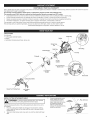
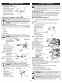
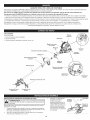
APPLiCATiONS
As a trimmer:
• Cutting grass and light weeds. Spark Plug
• Edging Muffler
• Decorative trimming around trees, fences, etc.
N
Starter Rope
Grip
On/Off Control
Shaft Grip
Oil Fill Plug
Fuel Cap
D-Handle
Attachment
Shaft
Throttle
Control
Red Cold Weather
Starter Lever
Cutting Head Shield
Convertible TM
Coupler
Air Filter
Cover
Primer Bulb
Hassle Free ® Catting Head
Line Cutting
Blade
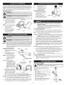
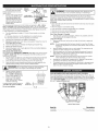
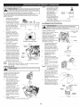
INSTALL CUTTING ATTACHMENT SHIELD 3. Using an appropriate screw \
-- i
_L_ WARNING: To prevent serious personal injury, never operate
the unit without the cutting attachment shield in place.
Use the following instructions ifthe cutting attachment shield on the unit is
not installed.
1. Place the cutting head shield onto the guard mount bracket, making
sure to align the holes on the shield with the ones in the guard mount
bracket. (Fig. 1)
2. Take the 2 shield screws and screw each one into the shield until finger
tight.
driver, tighten the screws
until the shield is firmly in
place. Make sure the screws
are tightened equally so
there is a balanced gap
between the bracket and the
shield on each side.
Cutting
Head Shield
Guard
Mount
Bracket
Fig. I

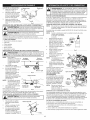
ADJUSTING THE D-HANDLE Shaft Grip D-Handle
1. Loosen the screws on the D-
handle (Fig. 2).
2. While holding the unit in the
operating position (Fig. 13),
position the D-handle to the
location that provides the Min. 6 in.
best grip. (15.24 cm)
3. Tighten the clamp screws _:;:_r_
evenly, until the D-handle is
Screw
secure.
Fig. 2
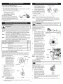
OPERATING THE CONVERTIBLE TM COUPLER SYSTEM
_ ARNING: Before beginning the use of any attachment, read
and understand the manual that came with the attachment. Follow
all safety information contained within.
_ ARNING: These attachments are to be snapped into the
primary hole only. Using the wrong hole could lead to personal
injury or damage to the unit.
The Convertible TM coupler system enables the use of these optional
attachments. For information about attachments, call 1=800=4=MY-HOME®.
• Edger
Cultivator
Turbo Blower
Brushcutter
Pole Saw
Hedge Trimmer
iNSTALLiNG THE TRIMMER ATTACHMENT OR OTHER ATTACHMENT
WARNING: Before operating this unit, be sure that the release |
button is fully snapped into the primary hole (Fig. 4), and that the
]
knob (Fig. 5) is securely tightened.
NOTE: To make installing or
removing the attachment
easier, place the unit on
the ground or on a work --
bench.
1. Turn knob counterclockwise
to loosen (Fig. 5).
2. While firmly holding the
trimmer attachment or other
attachment, push it straight
into the Convertible TM
coupler until the release
button snaps firmly into the
primary hole (Fig. 4).
NOTE: Aligning the release
button with the guide
recess will help
installation (Fig. 3).
3. Turn the knob clockwise to
tighten (Fig. 5).
NOTE: When using the line
trimmer or other
Convertible TM Release Button
C°upler k',, /
Guide Recess
Fig.3
Primary Hole
Attachment
Shaft
attachment to edge, lock
the attachment release Fig.4
button into the 90° hole (Fig. 5).
REMOVING THE TRIMMER ATTACHMENT OR OTHER ATTACHMENT
_ WARNING: To avoid serious personal injury and damage to the I
unit, shut the unit off before removing or installing attachment. J
1. Turn the knob 90° Edging Home
counterclockwise to loosen (Trimmer Only)
(Fig. 5).
2. Press and hold the release
button (Fig. 3).
3. While firmly holding the upper
shaft, pull the trimmer
attachment or other
attachment straight out of the
Convertible TM coupler (Fig. 4).
•Knob
Fig. 5
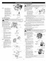
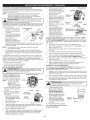
_ ARNING: OVERFILLING OIL CRANKCASE MAY CAUSE
SERIOUS PERSONAL INJURY. Check and maintain the proper oil
level in the crankcase; it is important and cannot be
overemphasized. Check the oil before each use and change it as
needed. See Changing the Oil.
RECOMMENDED OiL TYPE
Using the proper type and weight of oil in the crankcase is extremely important.
Check the oil before each use and change the oil regularly. Failure to use the
correct oil, or using dirty oil, can cause premature engine wear and failure.
Use a high-quality SAE 30 weight oil of API (American Petroleum Institute)
service class SF, SG, SH.
ADDING OiL TO CRANKCASE: iNiTiAL USE
NOTE: This unit is shipped without oil. In order to avoid damage to the
unit, put oil in the crankcase before attempting to start the unit.
The unit is supplied with one 3.04 fluid oz. (90 ml) bottle of SAE 30 SF, SG,
SH oil (Fig. 6).
NOTE: Save the bottle of oil. It can be used to measure the correct
amount during future oil changes. See Changing the Oil.
1. Unscrew the top of the bottle
of oil and remove the paper
seal covering the opening.
Replace the top. Next, cut
the tip off the funnel spout
(Fig. 6).
2. Place unit on a flat, level
surface.
Funnel t
3. Remove the oil fill plug from the Spout
crankcase (Fig. 8).
4. Pour the entire bottle of oil
into the oil fill hole (Fig. 7). Fig. 6
NOTE: Never add oil to the fuel
or fuel tank.
5. Wipe up any oil that may
have spilled and reinstall the
oil fill plug.
Check oil before each use and
change as needed. Refer to
Checking the Oil Level.
RECOMMENDED FUEL TYPE
Old fuel is the primary reason for
improper unit performance. Be oimFilmHome/
sure to use fresh, clean, unleaded
gasoline. Fig. 7
NOTE: Dispose of the old
gasoline in accordance oimFilmPmug
with federal, state and
local regulations.
NOTE: This is a four cycle
engine. In order to avoid
damage to the unit, do O-Ring
not mix oil with
gasoline.
Oil Fill
Definition of Blended Fuels Hole
Today's fuels are often a blend of
gasoline and oxygenates such as
ethanol, methanol or MTBE (ether). Fig. 8
Alcohol-blended fuel absorbs water. As little as 1% water in the fuel can make
fuel and oil separate or form acids when stored. Use fresh fuel (less than 30
days old), when using alcohol-blended fuel.
Using Blended Fuels
If choosing to use a blended fuel, or its use is unavoidable, follow
recommended precautions:
Always use fresh unleaded gasoline
Use the fuel additive STA-BIL® or an equivalent
Drain tank and run the engine dry before storing unit
Using Fuel Additives
WARNING: Gasoline is extremely flammable. Ignited vapors
may explode. Always stop the engine and allow it to cool before
filling the fuel tank. Do not smoke while filling the tank. Keep
sparks and open flames at a distance from the area.
WARNI NG: Add fuel in a clean, well ventilated outdoor area. Wipe
up any spilled fuel immediately. Avoid creating a source of ignition for
spilt fuel. Do not start the engine until fuel vapors dissipate.
5

The use of fuel additives, such as STA-BIL® Gas Stabilizer or an equivalent,
will inhibit corrosion and minimize the formation of gum deposits. Using a fuel
additive can keep fuel from forming harmful deposits in the carburetor for up to
six (6) months. Add 0.8 oz. (23 ml) of fuel additive per gallon of fuel according
to the instructions on the fuel additive container. NEVER add fuel additives
directly to the unit's gas tank.
FUELING THE UNIT
-- j
,_[_ WARNING: Remove fuel cap slowly to avoid injury from fuel
spray. Never operate the unit without the fuel cap securely in place.
_ ARNING: DO NOT USE E85 FUEL IN THiS UNIT. It has i
been proven that fuel containing greater than 10% ethanol will
1
likely damage this engine and void the warranty.
1. Remove the fuel cap (Fig. 9). Gas Can S
2. Place the gas container's
spout into the fill hole on the _ _/_===="_"_
fuel tank (Fig. 9) and fill the
tank.
NOTE: Do not overfill the tank.
3. Wipe up any gasoline that
may have spilled.
4. Reinstall the fuel cap.
5. Move the unit at least 30 ft. Fuel Tank
(9.1 m) from the fueling
source and site before
starting the engine.
"_out
Cap
Fig. 9
m
J_, I WARNING: Operate this unit only in a well-ventilated outdoor area.
I _ I Carbon monoxide exhaust fumes can be lethal in a confined area. I
A I WARNING: Avoid accidental starting. Make sure to be in the I
_:_ _starting position when pulling the starter rope (Fig. 12).To avoid serious
I
I injury, the operator and unit must be in a stable position while starting.
NOTE: This unit uses the Incredi-Pull TM starting system, which significantly
reduces the effort required to start the engine. There is no harsh
resistance when pulling the starter rope. Be aware that this starting
method is vastly different from (and much easier than) previous
starting techniques.
STARTING INSTRUCTIONS
1. Check the oil level in the
crankcase. Refer to Checking
the Oil Level.
2. Fill the fuel tank with fresh,
clean unleaded gasoline.
Refer to Fueling the Unit.
NOTE: There is no need to turn
the unit on. The On/Off
Control is in the ON (I)
position at all times
(Fig. 10).
IF COLD... Incold weather
conditions (below 40°F),
push the red cold weather
start lever (Fig. 11)down
to the closed position and
continue to step 3. DO
NOT push this lever down
if the temperature is
40°E
3. Fully press and release the
primer bulb 10 times, slowly.
Some amount of fuel should
Throttle Control
Fig. 10
Red Cold Weather
Starter Lever
Run/Open
Primer
Bulb
Close/Start
be visible in the primer bulb
(Fig. 11). If fuel can not be Fig. 11
seen in the bulb, press and release the bulb until fuel is visible.
4. With the unit in the starting position, do not squeeze the throttle control
(Fig. 12). Pull the starter rope in a controlled motion until unit starts.
IF COLD... In cold weather conditions (below 40°F), pull the red cold weather
start lever back up to the open position after the unit starts.
5. Once the unit starts, wait 60 seconds and then squeeze the throttle control.
6. Continue squeezing the throttle control for an additional 30 to 60 seconds
to let the engine warm up. The unit may be used during this time.
IR.. The engine does not start, Starting
go back to step 3. Position
IF,.. The engine stops while
squeezing the throttle,
go back to step 4.
STOPPING INSTRUCTIONS
1. Release the throttle control
and allow the engine to cool
down by idling.
2. Press and hold the On/Off
Control in the OFF (O) Throttle Control
position until the unit comes Fig. 12
to a complete stop. (Fig. 10)
NOTE= This Unit Can Use a Plug-in Power Start or Power Bit Start
Optional Accessory!
Please refer to the Plug-In Power Start or Power Bit Start operator's
manual for proper use of these features. (Items may be Sold
Separately! Please refer to page 9 of this manual for more information
about purchasing these accessories.)
STARTING INSTRUCTIONS
1. Check the oil level in the crankcase. Refer to Checking the Oil Level.
2. Fillthe fuel tank with fresh, clean unleaded gasoline. Refer to Fueling the Unit.
NOTE: There is no need to turn the unit on. The On/Off Control is in the
ON (I) position at all times (Fig. 10).
IF COLD... In cold weather conditions (below 40°F), push the red cold weather
start lever (Fig. 11) down to the closed position and continue to step 3.
DO NOT push this lever down if the temperature is above 40°E
3. Fully press and release the primer bulb 10 times, slowly. Some amount
of fuel should be visible in the primer bulb (Fig. 11). Iffuel can not be
seen in the bulb, press and release the bulb until fuel is visible.
4. With the unit in the starting position (Fig. 12). Place the Plug-In Power
Start or Power Bit Start into the back of the unit. Refer to Operation
section of the Plug-In Power Start or Power Bit Start operator's manual.
5. Do Not squeeze the throttle control, press and hold the Plug-In Plug-
In Power Start or drill's ON (I) button for 2 second intervals until unit
starts.
IF COLD... In cold weather conditions (below 40°F), pull the red cold weather
start lever back up to the open position after the unit starts.
6. Once the unit starts, remove the Plug-In Power Start or drill from the
rear of the unit and wait 60 seconds; then squeeze the throttle control.
7. Continue squeezing the throttle control for an additional 30 to 60 seconds
to let the engine warm up. The unit may be used during this time.
iF... The engine does not start, go back to step 3.
IF,.. The engine stops while squeezing the throttle, go back to step 4.
STOPPING INSTRUCTIONS
1. Release the throttle control and allow the engine to cool down by idling.
2. Press and hold the On/Off Control in the OFF (O) position until the unit
comes to a complete stop. (Fig. 10)
HOLDING THE TRIMMER
_ILL_ ARNING: Always wear eye, hearing, foot and body protection
to reduce the risk of injury when operating this unit.
Before operating the unit, stand in the
operating position (Fig. 13). Check for the
following:
• The operator is wearing eye protection and
proper clothing
With a slightly-bent right arm, the operator's
hand is holding the shaft grip
The operator's left arm is slightly bent, the
left hand holding the D-handle
The unit is at waist level
The trimmer attachment is parallel to the
ground and easily contacts the grass
without the need to bend over.

TIPS FOR BEST TRIMMING RESULTS
• Keep the trimmer attachment parallel to the ground.
• Trim only when grass and weeds are dry.
The cutting head and shield are designed to allow the unit to cut in either
direction, from right to left or left to right.
The life of the trimmer line is dependent upon:
Following the trimming tips _31_
- What vegetation is being cut
- Where vegetation is being cut
DECORATIVE TRIMMING
Decorative trimming is accomplished by
removing all vegetation around trees, posts,
fences and more. Rotate the whole unit so
that the trimmer attachment is at a 30° angle _ L _
to the ground (Fig. 14). Fig.14
MAINTENANCE SCHEDULE
-- i
_I_I_II_L_WARNING: To prevent serious injury, never perform maintenance
or repairs with unit running. Always service and repair a cool unit.
Perform these required maintenance procedures at the frequency stated in
the table. These procedures should also be a part of any seasonal tune-up.
NOTE: Some maintenance procedures may require special tools or skills. If
unsure about these procedures take the unit to Sears or other qualified
service dealer. Call 1=800-4-MY=HOME® for more information.
NOTE: Maintenance, replacement, or repair of the emission control devices
and system may be performed by a Sears or other qualified service
dealer. Call 1-800-4-MY-HOME® for more information.
NOTE: Please read the California/EPA statement that came with the unit for
a complete listing of terms and coverage for the emissions control
devices, such as the spark arrestor, muffler, carburetor, etc.
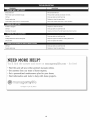
FREQUENCY MAINTENANCE REQUIRED SEE
Every 10 hours Clean air filter p. 8
At 10 hours Change oil p. 7
Check rocker arm to valve clearance and adjust p. 8
Check spark plug condition and gap p. 9
Every 40 hours Change oil p. 7
Check rocker arm to valve clearance and adjust p. 8
Check spark plug condition and gap p. 9
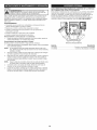
HASSLE-FREE TM LINE REPLACEMENT
Always use Craftsman Hassle-Free TM XTRA QUIET Spiral Line. Choose the
line size best suited for the job at hand. Red colored line is designed for
cutting grass and small weeds. Black colored line is designed for cutting
4.
larger weeds and light brush.
Glide Plate
NOTE: Before inserting new line
into the holes in the Arrow
cutting head, identify the
proper holes. Follow
directions as shown on
the glide plate. Do Not
attempt to remove the
cutting head from the
unit when replacing line.
Cuttinc Head
1. Remove the old line and line
glide plate from the cutting Fig. 15
head.
2. Clean entire surface of
cutting head.
3. Reinstall line glide plate (Fig.15).
Align arrow with:
A= when using medium (red) or
large (black)line
B- when using lines with
diameters smaller than
medium (red)line
NOTE: Line glide plate must be Fig. 16
reinstalled in cutting head
before inserting new line.
Insert both ends of your line through the proper holes in the side of the
cutting head (Fig. 16).
5. Pull the line and make sure
the line is against the hub and
is fully extended through the
positioning tunnels (Fig. 17).
6. Correctly installed line will be
the same length on both sides.
Some line breakage will occur from:
• Entanglement with foreign matter
Normal line fatigue
Attempting to cut thick, stalky
weeds
Positioning Tannem
Fig. 17
Forcing the line into objects such as walls or fence posts
NOTE: During normal use the trimming line may become worn unevenly
which may cause excessive vibrations in the unit. If this becomes
uncomfortable or uncontrollable, stop the unit and replace the line.
Refer to the Line Replacement instructions above.
CHECKING THE OIL LEVEL
m i
I _k WARNING: To avoid serious personal injury, always turn the
un t off and a ow it to cool before cleaning or maintaining it.
The importance of checking and
maintaining the proper oil level in
the crankcase cannot be
overemphasized. Check oil before
each use:
1. Stop the engine and allow oil
to drain into the crankcase.
2. Place the engine on a flat,
level surface with the cutting
head shield hanging off a work
bench or table to get a proper
oil level reading (Fig. 18).
3. Keep dirt, grass clippings
and other debris out of the
engine. Clean the area
around the oil fill plug before
removing it.
4. Remove the oil fill plug.
5. Look into the oil fill hole; use
a flashlight if needed. The oil
should be just touching the
inner most thread (Fig. 19).
6. Ifthe oil level is not touching
the inner most thread on the
oil fill hole, add a small
amount of oil to the oil fill hole
and recheck (Fig. 19). Repeat
this procedure until the oil
level reaches the innermost
thread on the oil fill hole.
NOTE: Do not overfill the unit.
NOTE: Make sure the O-ring is
in place on the oil fill plug
when checking and
changing the oil (Fig. 20).
CHANGING THE OIL
Fig. 18
Fig.19
OilFIllPlug
O-Ring
Oil Fill
Hole
Fig. 20
-- l
_ CAUTION: Wear gloves to prevent injury when handling the unit.
Change the oil per the
Maintenance Schedule. Change
the oil while the engine is still
warm. The oil will flow freely and
carry away more impurities.
1. Remove the oil fill plug.
2. Pour the oil out of the oil fill
hole and into a container by
tipping the unit to a vertical
position (Fig. 21). Allow ample
time for complete drainage.
3.
4.
Fig. 21
Wipe up any oil residue on the unit and clean up any oil that may have
spilled. Dispose of the oil according with federal, state and local
regulations.
Refill the crankcase with 3.04 fi.oz. (90 ml) of SAE 30 SF, SG, SH oil.

Fill Line --
NOTE: Use the bottle and
spout saved from initial
use to measure the
correct amount of oil.
The top of the label on
the bottle measures
approximately 3.04 fl.oz.
(90 ml) (Fig. 23). Check
the level, See Checking
the Oil Level. If the level
is low, add a small
amount of oil and
recheck. Do not overfill
(Fig. 22).
5. Replace the oil fill plug.
AiR FILTER MAINTENANCE
Fig. 22
Fig. 23
-- 1L_ ARNING: To avoid serious personal injury, always turn the
unit off and allow it to cool before cleaning or maintaining it.
Cleaning the Air Filter Air FimterCover
Clean and re-oil the air filter per
the Maintenance Schedule. It is
an important item to maintain.
Failure to maintain the air filter
properly can result in poor
performance or can cause
permanent damage to the engine.
1. Open the air filter cover. Push
the tab on the under side of
the cover inward. Then pull
the air filter cover out and up.
(Fig. 24).
2. Remove the air filter
(Fig. 24).
3. Wash the filter in detergent
and water (Fig. 25). Rinse the
filter thoroughly and allow it
to dry.
4. Apply enough clean SAE 30
motor oil to lightly coat the
filter (Fig. 26).
5. Squeeze the filter to spread
and remove excess oil (Fig. 27).
6. Replace the filter (Fig. 24).
NOTE: If operating the unit
without the air filter,
WiLL VOiD the warranty.
7. Reinstall the air filter cover.
Position the slots on the top
of the air filter cover onto the
tabs at the top of the back
plate (Fig. 28).
8. Swing the cover down until
the tab on the air filter
backplate snaps into place in
the slot on the air filter cover
(Fig. 24).
Fig. 24
Air Filter
Tab
Fig. 25
Fig. 26
Fig. 27
Fig. 28
iDLE SPEED ADJUSTMENT
_ ARNING: The cutting attachment may spin during idle speed
adjustments. Wear protective clothing and observe all safety
instructions to prevent serious personal injury.
The idle speed of the engine is
adjustable. An idle adjustment IdNeAdjustment
Screw
screw is between the air filter
cover and the engine starter
housing (Fig. 29).
NOTE: Careless adjustments
can seriously damage
the unit. Aside from idle
speed, only a Sears or
other qualified service
dealer should make Fig. 29
carburetor adjustments.
If, after checking the fuel and cleaning the air filter, the engine still will not
idle, adjust the idle speed screw as follows:
1. Start the engine and let it run at a high idle for a minute to warm up. Refer
to Starting/Stopping Instructions.
2. Release the throttle trigger and let the engine idle. Ifthe engine stops,
insert a small Phillips screwdriver in between the air filter cover and the
engine cover (Fig. 29). Turn the idle speed screw in, clockwise, 1/8 of a
turn at a time (as needed) until the engine idles smoothly.
NOTE: The cutting attachment should not rotate when the engine idles.
3. If the cutting attachment rotates when the engine idles, turn the idle
speed screw counterclockwise 1/8 of a turn at a time (as needed), to
reduce idle speed.
Checking the fuel, cleaning the air filter, and adjusting the idle speed should
solve most engine problems. If not and any of the following are true have the
unit serviced by a Sears or other qualified service dealer:
• the engine will not idle
the engine hesitates or stalls on acceleration
there is a loss of engine power
ROCKER ARM CLEARANCE
m ]
I A IWARNING: To avoid serious personal injury, always turn the
_unit off and allow it to cool before cleaning or maintaining it.
View of the Rear Engine Cover
This requires disassembly of the
engine. If unsure or unqualified to
perform this, take the unit to a Sears
or other qualified service dealer.
NOTE: Inspect the valve to Screws
rocker arm clearance
with a feeler gauge per
the Maintenance
Schedule.
The engine must be cold when
checking or adjusting the valve
clearance.
This task should be performed
inside, in a clean, dust free area.
1. Remove the six (6) screws on
the back of the engine cover
with a Flat-head or T-25 Torx
screwdriver (Fig. 30).
2. Disconnect the spark plug wire.
3. Clean dirt from around the
spark plug. Remove the spark
plug from the cylinder head by
turning a 5/8 in. socket
counterclockwise.
4. Remove the engine cover
(Fig. 30).
5. Clean dirt from around the
rocker arm cover. Remove Rocker
the screw holding the rocker Arms
arm cover with a large flat
blade screwdriver or Torx T-
25 bit (Fig. 31). Remove the
rocker arm cover and gasket.
6.
Fig. 30
Screws
Spark Plug
HoNe
Fig. 31
INTAKE
Adjusting Nuts
EXHAUST
Fig. 32
Pull the starter rope slowly to bring the piston to the top of its travel,
(known as top dead center). Check that:
The piston isat the top of its travel. This should be done by looking into the
spark plug hole. (Fig. 31)

Ifthesestatementsarenottrue,
repeatstep6.
7. Slidethefeelergaugebetween0.003-0.005i
therockerarmandthevalve (0.076-0.152ram)F-
returnspring.Measurethe
clearancebetweenthevalve
stemandrockerarm(Fig.33).
Measureboththeintakeand
exhaustvalves. Fig.33
Therecommendedclearanceforbothintakeandexhaustis.003- .006in.
(.076-0.152ram).Useastandardautomotive.005 in. (0.127 mm) feeler
gauge. The feeler gauge should slide between the rocker arm and valve stem
with a slight amount of resistance, without binding. See Figures 32 and 33.
8. If the clearance is not within specification:
a. Turn the adjusting nut using a 5/16 inch (8 mm) wrench or nut driver
(Fig. 33).
• To increase clearance, turn the adjusting nut counterclockwise.
To decrease clearance, turn the adjusting nut clockwise.
b. Recheck both clearances, and adjust as necessary.
9. Reinstall the rocker arm cover using a new gasket. Torque the screw to
20-30 inolb (2.2-3.4 Nora).
10. Check the spark plug and reinstall. See Replacing the Spark Plug.
11. Replace the spark plug wire.
12. Reinstall the engine cover. Check alignment of the cover before tightening
the screws. Tighten screws.
REPLACING THE SPARK PLUG
Use a replacement Champion ® #RDZ4H spark plug. The correct air gap
is 0.025 in. (0.635 ram). Remove the plug and check its condition per the
Maintenance Schedule.
1. Stop the engine and allow it to cool. Remove the six (6) screws on the back
of the engine cover with a Flat-head or T-25 Torx screwdriver (Fig. 30).
2. Grasp the plug wire firmly and pull the cap from the spark plug.
3. Clean dirt from around the spark plug. Remove the spark plug from the
cylinder head by turning a 5/8 in. socket counterclockwise.
-- ]
I A I WARNING: Do not sand blast, scrape or clean spark plug
the
engine could damage the cylinder.
_ electrodes. Grit in
• Both rocker arms move freely, Exhaust Rocker Arm CLEANING
and both valves are closed Adjusting --_..__ / Feemer
Nut o Gauge
4. Replace cracked, fouled or I I
dirty spark plug. Set the air
gap at 0.025 in. (0.635 ram)
using a feeler gauge (Fig. 34).
5. Install a correctly-gapped
spark plug in the cylinder
head. Turn the 5/8 in. socket
clockwise until snug.
If using a torque wrench torque to: 0.025 in. _,
110-120 in._lb. (12.3-13.5 Nora} (0.635ram} t
Do not over-tighten. Fig. 34
m
_iLL_ ARNING: To avoid serious personal injury, always turn the
unit off and allow it to cool before cleaning or maintaining it.
Use a small brush to clean off the outside of the unit. Do not use strong
detergents. Household cleaners that contain aromatic oils such as pine and
lemon, and solvents such as kerosene, can damage plastic housing or handle.
Wipe off any moisture with a soft cloth.
STORAGE
Never store the unit with fuel in the tank where fumes may reach an open
flame or spark.
Allow the engine to cool before storing.
Lock up the unit to prevent unauthorized use or damage.
Store the unit in a dry, well-ventilated area.
Store the unit out of the reach of children.
Short Term Storage (1=2 weeks)
1. Store the unit in a horizontal position. If this is not possible, store the
unit vertically with the engine at the top.
Long Term Storage
1. Remove the fuel cap, tip the unit and drain the fuel into an approved
container.
NOTE: Do not use gasoline that has been stored for more than 30 days.
Dispose of old gasoline in accordance with federal, state and local
regulations.
2. Start the engine and allow it to run until it stalls. This ensures that all
gasoline has been drained from the carburetor.
3. Allow the engine to cool. Remove the spark plug and put 5 drops of
high quality motor oil into the cylinder. Pull the starter rope slowly to
distribute the oil. Reinstall the spark plug.
NOTE: Remove the spark plug and drain all of the oil from the cylinder
before attempting to start the trimmer after storage.
4. Change the oil, referring to Changing the 0il. Dispose of the old oil in
accordance with federal, state and local regulations.
5. Thoroughly clean the unit and inspect for any loose or damaged parts.
Repair or replace damaged parts and tighten loose screws, nuts or
bolts. The unit is ready for storage.
PLUG=IN POWER START AND POWER BiT START FEATURES
This unit is designed to be started with an optional Plug-In Power Start or
Power Bit Start that are sold separately. If choosing to start the unit using
one of these features or have questions please contact your local retailer or
call 1-800-4=MY-HOME®, for more information and purchasing. You may
also go to www.craftsman.com.
Electric Start Feature
Item No. Description
316.85951 ..................................... Plug-In Power Start
316.85952 ........................................ Power Bit Start
9

PROBLEM SOLUTION
Empty fuel tank Fill fuel tank with fuel
m
Pdmer bu!b wasn!t pressed enough Press primer bulb fully and slowly 10 times
Old fuel
Fouled Spark plug
Cold weather start lever is in closed position
I
Air filter is plugged
Drain gas tank and add fresh fuel
Repiace 0r clean the Spaik plug
Move cold weather start lever to open position
Replace or clean the air filter
old fuel Drain gas tank and add fresh fuel
Improper idle speed
Old fuel
Cutting attachment bound with grass
Dirty air filter
Old fuel
Adjust according to the Idle Speed Adjustment section.
Drain gas tank and add fresh fuel
St0p the engine and Clean the Cutting attachment
Clean or replace the air filter
Drain gas tank and add fresh fuel
Fouled spark plug Replace 0r €lean the spark plug
£LP?
i_!!!!!!!!!!!il
10

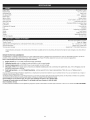
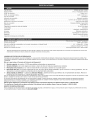
Engine Type .................................................................................................... Air-Cooled, 4-Cycle
Displacement ..................................................................................................... 1.8 cu. in. (29 cc)
Operating RPM ........................................................................................................ 6,800+ rpm
Idle Speed RPM .................................................................................................. 2,800 - 3,600 rpm
Ignition Type ............................................................................................................ Electronic
Ignition Switch ...................................................................................................... Rocker Switch
Valve clearance ...................................................................................... 0.003-0.006 in. (0.076-0.152 mm)
Spark Plug Gap ............................................................................................... 0.025 inch (0.635 mm)
Spark Plug ........................................................................................ Champion RDZ4H or equivalent plug
Lubrication ............................................................................................................ SAE 30 Oil
Crankcase Oil Capacity ............................................................................................... 3.04 oz (90 ml)
Fuel ................................................................................................................... Unleaded
Carburetor .................................................................................................. Diaphragm, All-Position
Starter .............................................................................................................. Auto Rewind
Muffler ......................................................................................................... Baffled with Guard
Throttle ...................................................................................................... Manual Spring Return
Fuel Tank Capacity ................................................................................................... 14 oz (414 ml)
Drive Shaft Housing .................................................................................. Steel Tube (Convertible TM Coupler)
Throttle Control ................................................................................................... Finger-Tip Trigger
Approximate Unit Weight (No fuel, with Hassle Free@, shield, and D-handle) ........................................... 11.5 - 13.0 Ibs (5.2 - 5.9 kg)
Trimmer Mechanism ........................................................................................ Hassle Free TM PLUS Head
Trimming Line Diameter ............................................................................ Hassle Free TM XTRA QUIET Spiral Line
* All specifications are based on the latest product information available at the time of printing. We reserve the right to make changes at any time without
notice.
REPAIR PROTECTION AGREEMENTS
Congratulations on making a smart purchase. Your new Craftsman@ product is designed and manufactured for years of dependable operation. But like all
products, it may require repair from time to time. That's when having a Repair Protection Agreement can save you money and aggravation.
Here is what the Repair Protection Plan Agreement includes:
[] Expert service by our 10,000 professional repair specialists
[] Unlimited service and no charge for parts and labor on all covered repairs
[] Product replacement up to $1500 if your cover product can not be fixed
[] Discount of 10% from regular price of service and related installed parts not covered by the agreement; also, 10% off regular price of
preventive maintenance checks
[] Fast help by phone - we call it Rapid Resolution - phone support from a Sears representative. Think of us as a "talking owner's
manual."
Once you purchase the Repair Protection Agreement, a simple phone call is all that it takes for you to schedule service. You can call anytime day or night, or
schedule a service appointment online.
The Repair Protection Agreement is a risk-free purchase. Ifyou cancel for any reason during the product warranty period, we will provide a full refund. Or a prorated
refund anytime after the product warranty period expires. Purchase your Repair Protection Agreement today!
Some limitations and exclusions apply. For prices and additional information call 1=800=827=6655.
*Coverage in Canada varies on some items. For full details call Sears Canada at 1=800=361 =6665.
Sears installation Service
For Sears professional installation of home appliances, garage door openers, water heaters, and other major home items, in the U.S.A. or Canada call 1-800-4-MY-HOME ®.
11
Page is loading ...

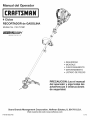
Manual del Operador
M
4 Ciclos
RECORTADOR de GASOLINA
Modelo No. 316.791961
INCflEDI.PULL_'_
UNBELIEVABLE STARTING EA S E
o SEGURIDAD
MONTAJE
FUNCIONAMIENTO
MANTENIMIENTO
LISTADO DE PIEZAS
PRECAUCION: Lea el manual
del operador y siga todas ias
advertencias e instrucciones
de seguridad.
Sears Brands Management Corporation, Hoffman Estates, IL 60179 U.S.A.
Visite nuestro sitio web: www.craftsman.com
P/N 769-06213 PO0 11/10
Page is loading ...
Page is loading ...
Page is loading ...
Page is loading ...
Page is loading ...
Page is loading ...
Page is loading ...
Page is loading ...
Page is loading ...
Page is loading ...
Page is loading ...
Page is loading ...
Page is loading ...
Page is loading ...
Page is loading ...
Page is loading ...

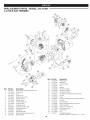
REPLACEMENT PARTS - MODEL 316.791961
4-CYCLE GAS TRIMMER
Item Part No. Description
17 753-05246 Muffler Screw
18 753-05784 Spark Plug
%----(_) 19 753-05247 Insulator Gasket
20 753-05248 Nut
21 753-05249 Insulator
Item Part No. Description 22 753-05366 Carburetor Gasket
1 753-06113 Engine Cover Assembly (includes 2 & 3) 23 753-06258 Carburetor w/Primer
2 753-04595 Cover Screw 24 791-181751 Air Cleaner O-Ring
3 791-181003 Screw 25 753-05831 Air Cleaner Cover Assembly (includes 26)
4 753-05901 Rocker Cover 26 753-05254 Air Filter
5 753-05902 Rocker Cover O-Ring 27 753-05253 Screw
6 753-05910 Cylinder O-Ring 28 753-06240 Fuel Tank Assembly w/Fuel Lines (includes 29)
7 791-182379 Breather Hose 29 753-1229 Fuel Cap
8 753-05408 Oil Plug (includes 9) 30 753-05259 Fuel Tank Pads
9 791-182290 Oil Plug O-Ring 31 753-06498 Starter Housing Assembly (includes 3)
10 753-06111 Crankcase Cover 32 753-06281 Clutch Assembly
11 753-05238 Crankcase Cover O-ring 33 753-05263 Clutch Cover (includes 2)
12 753-06221 Flywheel Assembly 34 791-182519 Anti-Rotation Screw
13 753-05264 Lead Wires 35 753-04003 Clamp Screw
14 753-05447 Module Assembly 36 791-180217 Nut
15 753-05245 Muffler Assembly (includes 16 & 17) 37 753-06317 Shortblock Assembly
16 753-05244 Muffler Gasket (includes Crankcase, Cylinder, 3-9, 11,14 & 18)
3O

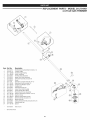
REPLACEMENT PARTS - MODEL 316.791961
4-CYCLE GAS TRIMMER
item Part No.
1 753-04234
2 753-04119
3 791-182690
4 791-182405
5 753-05266
6 753-04236
7 753-06039
8 753-06040
9 753-1190
10 791-181981
11 791-182057
12 791-181617
13 753-04386
14 753-06139
15 753-05267
16 753-06125
17 791-182193
18 791-182195
19 791-182519
20 753-06292
21 753-06126
22 753-05489
23 753-05036
24 791-182196
Description
Throttle Housing Assembly (includes 2-4)
Throttle Trigger
Throttle Trigger Spring
Switch Assembly
Throttle Cable Assembly
Upper Drive Shaft Assembly
D-Handle Assembly (includes 8)
Screw
Split Boom Coupler (includes 10-13)
Adjustment Knob (includes 13)
Coupler Anti-Rotation Screw
Coupler Bolt
Adjustment Knob Nut
Lower Drive Shaft Housing
Lower Flexible Drive Shaft
Shield Mount Screw Assembly
Gearbox Assembly (includes 18 & 19)
Gearbox Screw
Gearbox Anti-Rotation Screw
Shield Assembly (includes 21)
Blade Assembly
Cutting Head Assembly (includes 23 & 24)
Cutting Head Cap
Spacer
* 753-05038 Tube of Line
* Items Not Shown
31

Your Home
For troubleshooting, product manuals and expert advice:
managemylife
www.managemylife.com
For repair - in your home - of all major brand appliances,
lawn and garden equipment, or heating and cooling systems,
no matter who made it, no matter who sold it!
For the replacement parts, accessories and
owner's manuals that you need to do-it-yourself.
For Sears professional installation of home appliances
and items like garage door openers and water heaters.
1-800-4-MY-HOME ® ( -8oo-469-4663)
Call anytime, day or night (U,S,A, and Canada)
www.sears.com www.sears.ca
Our Home
For repair of carry-in items like vacuums, lawn equipment,
and electronics, call anytime for the location of your nearest
Sears Parts & Repair Service Center
1-800-488-1222 (U.S.A.) 1-800-469-4663 (Canada)
www.sears.com www.sears.ca
To purchase a protection agreement on a product serviced by Sears:
1-800-827-6655 (U.S.A.) 1-800-361-6665 (Canada)
Para pedir servicio de reparaci6n
a domicilio, y para ordenar piezas:
1-888-SU-HOGAR ®
(1-888-784-6427)
www.sears.com
Au Canada pour service en fran(_ais:
1=800=LE=FOYER Mc
(1-800-533-6937
www.sears.ca
® Registered Trademark / TMTrademark of KCD IP,LLC in the United States, or Sears Brands, LLC in other countries
® Marca Registrada / TMMarca de F&brica de KCD IP, LLC en Estados Unidos, o Sears Brands, LLC in otros paises
MCMarque de commerce / MDMarque d6pos6e de Sears Brands, LLC
-
 1
1
-
 2
2
-
 3
3
-
 4
4
-
 5
5
-
 6
6
-
 7
7
-
 8
8
-
 9
9
-
 10
10
-
 11
11
-
 12
12
-
 13
13
-
 14
14
-
 15
15
-
 16
16
-
 17
17
-
 18
18
-
 19
19
-
 20
20
-
 21
21
-
 22
22
-
 23
23
-
 24
24
-
 25
25
-
 26
26
-
 27
27
-
 28
28
-
 29
29
-
 30
30
-
 31
31
-
 32
32


Craftsman 316.791961 User manual
- Category
- Grass trimmers
- Type
- User manual
Ask a question and I''ll find the answer in the document
Finding information in a document is now easier with AI
in other languages
Related papers
-
Craftsman 316791200 Owner's manual
-
-
-
-
Craftsman 316711930 Owner's manual
-
-
-
-
-