Page is loading ...

For more information, visit www.desatech.com
WARNING: If the information in this manual is not fol-
— WHAT TO DO IF YOU SMELL GAS
• Do not touch any electrical switch; do not use any
-
(VENT-FREE) GAS STOVE HEATER
OWNER’S OPERATION AND INSTALLATION MANUAL
MODELS SL30PT AND SL30NT SERIES THERMOSTAT CONTROL
GAS LOG HEATER (BURNER SySTEM FOR CAST IRON STOVES)

www.desatech.com
115580-01B2
SAFETy INFORMATION
TABLE OF CONTENTS
Safety Information ............................................... 2
Product Identication ........................................... 4
Local Codes......................................................... 4
Product Features ................................................. 5
Air For Combustion and Ventilation ..................... 5
Installation ........................................................... 7
Operating Heater ............................................... 15
Inspecting Burners............................................. 16
Cleaning and Maintenance ................................ 17
Troubleshooting ................................................. 18
Specications .................................................... 21
Service Hints ..................................................... 21
Technical Service............................................... 21
Replacement Parts ............................................ 21
Accessories ....................................................... 21
Illustrated Parts Breakdown and Parts List........ 22
Parts Centrals .................................................... 26
Warranty Information ...........................Back Cover
-
-
teration, service or main-
tenance can cause in-
Refer to this manual for
correct installation and
For assistance or addi-
tional information con-
WARNING: This is an un-
the room in which it is
and ventilation air must
Air
for Combustion and Ven-
tilation
-
stalled in an aftermarket,*
-
State of Massachusetts: The installation
must be made by a licensed plumber or
gas tter in the Commonwealth of Mas-
sachusetts.
Sellers of unvented propane or natural
gas-red supplemental room heaters shall
provide to each purchaser a copy of 527
CMR 30 upon sale of the unit.
Vent-free gas products are prohibited for
bedroom and bathroom installation in the
Commonwealth of Massachusetts.

www.desatech.com
115580-01B 3
-
use of this heater can cause seri-
Early signs of carbon
monoxide poisoning resemble the u, with head-
aches, dizziness or nausea. If you have these signs,
the heater may not be working properly. Get fresh
air at once! Have heater serviced. Some people
are more affected by carbon monoxide than others.
These include pregnant women, people with heart
or lung disease or anemia, those under the inuence
of alcohol and those at high altitudes.
Natural and propane/
LP gases are odorless. An odor-making agent is
added to these gases. The odor helps you detect a gas
leak. However, the odor added to the gas can fade.
Gas may be present even though no odor exists.
Make certain you read and understand all warn-
ings. Keep this manual for reference. It is your
guide to safe and proper operation of this heater.
this heater or its controls can
WARNING: Do not allow fans
SAFETy INFORMATION
Continued
WARNING: Do not use a
-
and adults away from hot surface
-
-
-
dren when they are in the room
-
-
1. This appliance is only for use with the type of
gas indicated on the rating plate. This appliance
is not convertible for use with other gases.
2. Do not place propane/LP supply tank(s) in-
side any structure. Locate propane/LP supply
tank(s) outdoors (propane/LP units only).
3. If you smell gas
• shut off gas supply
• do not try to light any appliance
• do not touch any electrical switch; do not use
any phone in your building
• immediately call your gas supplier from a
neighbor’s phone. Follow the gas supplier’s
instructions
• if you cannot reach your gas supplier, call
the re department

www.desatech.com
115580-01B4
4. This heater shall not be installed in a bedroom
or bathroom.
5. Do not place stove directly on carpeting,
vinyl tile or any combustible material other
than wood. The stove must set on a metal
or wood panel extending the full width and
depth of the appliance.
6. Do not use this stove as a wood burning re-
place. Use only model SL30PT or SL30NT
vent-free gas log heater.
7. Do not add extra logs or ornaments such as pine
cones, vermiculite or rock wool. Using these
added items can cause sooting.
8. This log heater is designed to be smokeless. If
logs ever appear to smoke, turn off heater and
call a qualied service person. Note: During
initial operation, slight smoking could occur
due to log curing and heater burning manu-
facturing residues.
9. To prevent the creation of soot, follow the
instructions in Cleaning and Maintenance,
page 17.
10. Before using furniture polish, wax, carpet
cleaners or similar products, turn heater off.
If heated, the vapors from these products may
create a white powder residue within burner
box or on adjacent walls or furniture.
11. This heater needs fresh, outside air ventilation
to run properly. This heater has an Oxygen De-
pletion Sensing (ODS) safety shutoff system.
The ODS shuts down the heater if not enough
fresh air is available. See Air for Combustion
and Ventilation, page 5. If heater keeps shutting
off, see Troubleshooting, page 18.
12. Do not run heater
• where ammable liquids or vapors are used
or stored
• under dusty conditions
13. Do not use this stove to cook food or burn paper
or other objects.
14. Do not use heater if any part has been exposed
to or under water. Immediately call a qualied
service technician to inspect the room heater
and to replace any part of the control system and
any gas control which has been under water.
15. Do not operate heater if any log is broken. Do
not operate heater if a log is chipped (dime-
sized or larger).
SAFETy INFORMATION
Continued
16. Turn heater off and let cool before servicing.
Only a qualied service person should service
and repair heater.
17. Operating heater above elevations of 4,500
feet could cause pilot outage.
18. To prevent performance problems, the use of a
propane/LP tank of less than 100 lb. capacity is
not recommended (propane/LP units only).
19. Provide adequate clearances around air
openings.
PRODUCT
IDENTIFICATION
Figure 1 - Typical Stove Cabinet Model
with Comfort Glow Gas Log Heater
Stove
Body
Stove Door (Shown
in the open position)
Piezo
Ignitor
Control
Knob
One Piece
Log Set
Inside Stove
Cavity
LOCAL CODES
Install and use heater with care. Follow all local
codes. In the absence of local codes, use the lat-
est edition of The National Fuel Gas Code ANSI
Z223.1/NFPA 54*.
*Available from:
American National Standards Institute, Inc.
1430 Broadway
New York, NY 10018
National Fire Protection Association, Inc.
Batterymarch Park
Quincy, MA 02269

www.desatech.com
115580-01B 5
PRODUCT FEATURES
OpERATION
This heater is clean burning. It requires no outside
venting. There is no heat loss out a vent or up a
chimney. Heat is generated by realistic, dancing
yellow ames. This heater is designed for vent-free
operation. State and local codes in some areas
prohibit the use of vent-free heaters.
SAFETY pILOT
This heater has a pilot with an Oxygen Deple-
tion Sensing (ODS) safety shutoff system. The
ODS/pilot is a required feature for vent-free room
heaters. The ODS/pilot shuts off the heater if there
is not enough fresh air.
pIEzO IGNITION SYSTEM
This heater has a piezo ignitor. This system re-
quires no matches, batteries or other sources to
light heater.
AIR FOR COMBUSTION
AND VENTILATION
WARNING: This heater shall
-
-
Today’s homes are built more energy efcient
than ever. New materials, increased insulation and
new construction methods help reduce heat loss
in homes. Home owners weather strip and caulk
around windows and doors to keep the cold air out
and the warm air in. During heating months, home
owners want their homes as airtight as possible.
While it is good to make your home energy ef-
cient, your home needs to breathe. Fresh air must
enter your home. All fuel-burning appliances need
fresh air for proper combustion and ventilation.
Exhaust fans, replaces, clothes dryers and fuel
burning appliances draw air from the house to
operate. You must provide adequate fresh air for
these appliances. This will insure proper venting
of vented fuel-burning appliances.
pROVIDING ADEQUATE
VENTILATION
The following are excerpts from National Fuel
Gas Code, ANSI Z223.1/NFPA 54, Section 5.3, Air
for Combustion and Ventilation.
All spaces in homes fall into one of the three fol-
lowing ventilation classications:
1. Unusually Tight Construction
2. Unconned Space
3. Conned Space
The information on pages 5 through 7 will help
you classify your space and provide adequate
ventilation.
The air that leaks around doors and windows
may provide enough fresh air for combustion and
ventilation. However, in buildings of unusually
tight construction, you must provide additional
fresh air.
construction where:
-
2
and
and
-
If your home meets all of the three criteria
Ventilation Air From Outdoors,
If your home does not meet all of the
Determin-
ing Fresh-Air Flow For Heater Location,

www.desatech.com
115580-01B6
The National Fuel Gas Code ANSI Z223.1/NFPA
54 denes a conned space as a space whose
volume is less than 50 cubic feet per 1,000 Btu
per hour (4.8 m
3
per kw) of the aggregate input
rating of all appliances installed in that space and
an unconned space as a space whose volume is
not less than 50 cubic feet per 1,000 Btu per hour
(4.8 m
3
per kw) of the aggregate input rating of
all appliances installed in that space. Rooms com-
municating directly with the space in which the
appliances are installed*, through openings not
furnished with doors, are considered a part of the
unconned space.
* Adjoining rooms are communicating only if
there are doorless passageways or ventilation grills
between them.
DETERMINING FRESH-AIR FLOW
Use this work sheet to determine if you have a
conned or unconned space.
Includes the room in which you will
install heater plus any adjoining rooms with door-
less passageways or ventilation grills between
the rooms.
1. Determine the volume of the space (length x
width x height).
Length x Width x Height = cu. ft. (volume
of space)
Example: Space size 20 ft. (length) x 16 ft.
(width) x 8 ft. (ceiling height) = 2560 cu. ft.
(volume of space)
If additional ventilation to adjoining room is sup-
plied with grills or openings, add the volume of
these rooms to the total volume of the space.
2. Multiply the space volume by 20 to determine
the maximum Btu/Hr the space can support.
(volume of space) x 20 = (maximum Btu/Hr
the space can support)
Example: 2560 cu. ft. (volume of space) x 20 =
51,200 (maximum Btu/Hr the space can support)
AIR FOR COMBUSTION
AND VENTILATION
Continued
3. Add the Btu/Hr of all fuel burning appliances
in the space.
Vent-free heater _________ Btu/Hr
Gas water heater* _________ Btu/Hr
Gas furnace ________ Btu/Hr
Vented gas heater ________ Btu/Hr
Gas replace logs ________ Btu/Hr
Other gas appliances* + ________ Btu/Hr
Total = ________ Btu/Hr
* Do not include direct-vent gas appliances.
Direct-vent draws combustion air from the
outdoors and vents to the outdoors.
Example:
Gas water heater ________ Btu/Hr
Vent-free heater + ________ Btu/Hr
Total = ________ Btu/Hr
4. Compare the maximum Btu/Hr the space can
support with the actual amount of Btu/Hr used.
_____________Btu/Hr (maximum the space
can support)
___________ Btu/Hr (actual amount of
Btu/Hr used)
Example: 51,200 Btu/Hr (maximum the
space can support)
70,000 Btu/Hr (actual amount
of Btu/Hr used)
The space in the above example is a conned space
because the actual Btu/Hr used is more than the maxi-
mum Btu/Hr the space can support. You must provide
additional fresh air. Your options are as follows:
A. Rework worksheet, adding the space of an
adjoining room. If the extra space provides an
unconfined space, remove door to adjoining
room or add ventilation grills between rooms. See
Ventilation Air From Inside Building, page 7.
B. Vent room directly to the outdoors. See Ven-
tilation Air From Outdoors, page 7.
C. Install a lower Btu/Hr heater, if lower Btu/Hr
size makes room unconned.
If the actual Btu/Hr used is less than the
maximum Btu/Hr the space can support, the
space is an unconned space. You will need
no additional fresh air ventilation.
40,000
30,000
70,000

www.desatech.com
115580-01B 7
AIR FOR COMBUSTION
AND VENTILATION
Continued
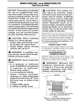
WARNING: If the area in
-
in the National Fuel Gas Code,
ANSI Z223.1/NFPA 54, Section
5.3
VENTILATION AIR
This fresh air would come from an adjoining un-
conned space. When ventilating to an adjoining
unconned space, you must provide two perma-
nent openings: one within 12" of the ceiling and
one within 12" of the oor on the wall connecting
the two spaces (see options 1 and 2, Figure 2). You
can also remove door into adjoining room (see
option 3, Figure 2). Follow the National Fuel Gas
Code, ANSI Z223.1/NFPA 54, Section 5.3, Air for
Combustion and Ventilation for required size of
ventilation grills or ducts.
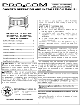
INSTALLATION
-
-
Figure 2 - Ventilation Air from Inside
Building
Or
Remove
Door into
Adjoining
Room,
Option
3
Ventilation Grills
Into Adjoining Room,
Option 2
Ventilation
Grills
Into Adjoining
Room,
Option 1
12"
12"
Figure 3 - Ventilation Air from Outdoors
Outlet
Air
Ventilated
Attic
Outlet
A
ir
Inlet
Air
Inlet Air
Ventilated
Crawl Space
To
Crawl
Space
To Attic
Ventilation Air From Outdoors
Provide extra fresh air by using ventilation grills or
ducts. You must provide two permanent openings:
one within 12" of the ceiling and one within 12"
of the oor. Connect these items directly to the
outdoors or spaces open to the outdoors. These
spaces include attics and crawl spaces. Follow the
National Fuel Gas Code, ANSI Z223.1/NFPA 54,
Section 5.3, Air for Combustion and Ventilation for
required size of ventilation grills or ducts.
IMPORTANT: Do not provide openings for inlet
or outlet air into attic if attic has a thermostat-
controlled power vent. Heated air entering the attic
will activate the power vent.

www.desatech.com
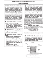
115580-01B8
WARNING: Never install the
heater
• in a recreational vehicle
• where curtains, furniture,
heater
• in windy or drafty areas
move heat to wall surfaces next
-
IMPORTANT: Vent-free heaters add moisture to
the air. Although this is benecial, installing heater
in rooms without enough ventilation air may cause
mildew to form from too much moisture. See Air
for Combustion and Ventilation, page 5.
Use only the correct gas type (natural or propane/LP)
for your unit. If your gas supply is not correct, do not
install heater. Call dealer where you bought heater
for proper type heater.
-
INSTALLATION
Continued
WARNING: Maintain the
Carefully follow the instructions below. This stove
is a freestanding unit designed to set directly on the
oor. IMPORTANT: You must maintain minimum
wall and ceiling clearances during installation.
The minimum clearances are shown in Figure 4.
Measure from outermost point of stove top.
A. Clearances from outermost point of stove top
to any combustible side wall should not be
less than 12".
B. Clearances from outermost point of stove top
to any combustible back wall should not be less
than 6" (includes corner installations).
C. Clearances from the stove top to the ceiling
should not be less than 48".
12"
Minimum
12"
Minimum
48"
Minimum
Ceiling
Side Wall Side Wall
Back Wall
Side Wall Side Wall
12 "
Minimum
12 "
Minimum
6 "
Minimum
Corner
Wall
Wall
6 "
Minimum
6 "
Minimum
6"
Minimum
48"
Minimum
Ceiling
Floor
Back
Wall
Figure 4 - Minimum Clearance to Walls
and Ceiling (Stove May Vary Depending
on Model)

www.desatech.com
115580-01B 9
1. Lift off corrugated box enclosing stove
body crating.
2. Remove all screws fastening the wood frame
enclosure. Spread wood frame open and lift
away from plastic-bagged stove body. The
bottom pieces of pallet wood will remain
bolted to the stove body.
3. Remove plastic bag from stove body.
4. Remove back panel from stove (see Figure 5).
Use an adjustable wrench or a 10 mm socket.
Remove six (6) bolts and washers. Keep bolts
and washers to reattach back panel later.
5. Remove all contents from inside stove cavity.
Contents include:
(1) - Stove bottom
(4) - Legs (Amity models include leg
leveler bolts)
(1) - Bottom door
(1) - Top grate
(1) - Hardware kit bag with fasteners
6. Carefully lay stove body on back to attach bottom
components to stove body (see Figure 6). Rest
stove on drop cloth or blanket to avoid scratching
stove edges.
INSTALLATION
Continued
Figure 5 - Removing Back Panel
Bolt
Product
Identication
Label
Back Stove
Panel
Figure 6 - Laying Down Stove On Side (Stove Style May Vary Depending on Model)
Front of
Stove
Unit
Pallet Wood
Bolted to
Stove Body
Bottom
Top of
Stove Unit
Front of Stove
Unit
Top of
Stove
Unit
Drop Cloth/
Blanket
7. Remove remaining pallet wood attached to
bottom of stove body (see Figure 7). Use an
adjustable wrench to remove bolts.
8. Fasten each leg to stove with four (4) bolts.
Use a at screw driver to tighten bolt to leg.
Thread bolt in tapped holes on stove body (see
Figure 8 and Figure 9, page 10).
Figure 7 - Removing Pallet Wood From
The Bottom of The Stove
Pallet
Wood
Bolt
Bottom Of
Stove Unit
Front
Pallet
Wood
Figure 8 - Locating Threaded Holes
for Stove Bottom, Legs and Door
Attachment (Appearance May Vary
Depending on Model)
Leg
Hole
Leg
Hole
Leg
Hole
Leg Hole
Door Hinge
Step Bolt Hole
Door Catch Bolt
With Adjustable
Hex Nuts Hole
Stove
Bottom
Holes
Front
Bottom Of Stove Unit

www.desatech.com
115580-01B10
INSTALLATION
Continued
9. Fasten stove bottom to stove with four (4)
M6 x 1 - 25 mm bolts. Use a at washer and
lock washer with each bolt. Tighten bolts into
threaded holes on stove body (see Figure 10
and Figure 8 on page 9). Use an adjustable
wrench or a 10 mm socket.
10. Attach stove door by inserting step bolt
through door hinge pivot holes and into
threaded hole in stove body (see Figure 11).
Use an adjustable wrench or a 12 mm socket
to fasten step bolt. Tighten step bolt until snug.
Make sure door moves freely.
11. Install door catch bolt (M8 x 1.25-55 mm with
two M8 hex nuts) into threaded hole on stove
body (see Figure 8, page 9). Use an adjustable
wrench or a 12 mm socket. The catch bolt has
two hex nuts attached to it (see Figure 12). The
top nut is a bolt stop and the bottom nut is for
door leveling adjustment.
12. Check general catch bolt alignment with door
claw. Make nal adjustment and door leveling
after stove is in normal standing position.
13. Carefully lift stove back up on its four at-
tached legs.
Figure 9 - Attaching Stove Legs
Bottom Of
Stove Unit
Leg
Bolt
Figure 10 - Attaching Stove Bottom
Bottom Of
Stove Unit
Bolt
Washers
Stove
Bottom
14. If available, install gas log heater inside stove
cavity before installing the back panel (see In-
stalling Gas Log Heater Into Stove, page 11).
15. Fasten back panel to stove with six (6) M6 x 1
- 20 mm bolts and washers. Make sure product
identication label is located on the outside in
lower left-hand corner.
Figure 11 - Attaching Stove Door
(Appearance May Vary Depending on
Model)
Step
Bolt
Door
Hinge
Threaded
Hole
Stove Door
Stove Bottom
Bolt
Shoulder
Door
Hinge
Step
Bolt
Bolt
Shoulder
Adjusting
Nut
Bolt Stop
Catch Bolt
Door Claw
Door
Figure 12 - Catch Bolt and Door Claw
Orientation

www.desatech.com
115580-01B 11
INSTALLING GAS LOG HEATER
INTO STOVE
1. Remove log and gas log heater from carton.
Note: Do not pick up gas log heater by the
burner itself. This could damage heater. Al-
ways handle the gas log heater by the heater
base only.
2. Remove all protective packaging applied to
log and gas log heater for shipment.
3. Check all items for any shipping damage. If
damaged, promptly inform dealer where you
bought heater.
4. If not already removed, remove back panel
from assembled stove body (see Figure 5,
page 9). Use an adjustable wrench or a 10 mm
socket. Remove six (6) bolts and washers. Keep
bolts and washers to reattach back panel later.
5. Set gas log heater inside stove (see Figure
13). Make sure control knob extensions pass
through bottom front opening.
6. Align outside holes on heater base with four
(4) mounting holes on the stove bottom (see
Figure 13).
7. Fasten heater base to stove bottom with #10-24
x .50 bolts and hex nuts provided with gas log
heater (see Figure 14). Attachment hardware
is factory packed inside plastic bag with
installation manual and owner’s registration
card. Push bolt through heater base mounting
hole and through stove bottom. Connect hex
nut to bolt on underside of stove bottom. The
bolt hex head is for a 5/16" socket and the hex
nuts are for a 3/8" socket. If sockets are not
available, use adjustable wrenches.
INSTALLATION
Continued
Figure 13 - Placing Heater Base In Stove
Cavity (Appearance May Vary Depending
on Model)
Bottom
Front
Opening
Stove
Bottom
Burner
Bolt
Heater
Base
Figure 14 - Fastening Heater Base to
Stove Drop Bottom
Stove Bottom
Heater
Base
Bolt
Hex Nut
One-
Piece
Log Set
"U" Shaped Cutout
in Chassis
Burner
Middle
Section at
Bottom of
Log Set
Figure 15 - Installing One-Piece Stove
Log Set
Heater
Base
8. Set one-piece log on heater base as shown in
Figure 15. Make sure middle section at bot-
tom of log is seated into "U" shaped cutout in
center of heater base. Log will t securely on
base. IMPORTANT: Make sure log does not
cover any burner ports and does not touch the
stove cavity (see Figure 16).
9. Fasten back panel to stove with six (6) M6
x 1.20 mm bolts and washers. Make sure
product identication label is located on the
outside lower left-hand corner.
10. Place freestanding stove in desired position
in room. Be sure to maintain clearances to
combustibles as outlined on page 8.
Burner Porting Areas (double
slotted rectangular openings)
Figure 16 - Top View of One-Piece Log
Set on Gas Log Heater
Safety Pilot Location
One-Piece
Log Set

www.desatech.com
115580-01B12
INSTALLATION
Continued
-
-
-
units, never connect heater to
Installation Items Needed
Before installing heater, make sure you have the
items listed below.
• external regulator for propane/LP units
(supplied by installer)
• piping (check local codes)
• sealant (resistant to propane/LP gas)
• equipment shutoff valve *
• test gauge connection *
• sediment trap
• tee joint
• pipe wrench
* A CSA design-certied equipment shutoff valve
with 1/8" NPT tap is an acceptable alternative to
test gauge connection. Purchase the optional CSA
design-certied equipment shutoff valve from your
dealer. See Accessories, page 21.
Figure 17 - Gas Regulator Location and
Gas Line Access Into Stove Cabinet
Back
Stove
Panel
Front of
Stove
Unit
Gas Inlet
Connection
Access
Product
Identica-
tion Label
Gas Log Heater
Back View
Side View
The gas inlet connection for the stove heater is
located on the lower right-hand side of the stove
when viewed from the front of the unit. The gas
connection can be made either through the bottom
right side or through the lower back opening as
illustrated in Figure 17. Make sure gas log heater
is secured to the stove cavity assembly.
For propane/LP gas, the installer must supply
an external regulator. The external regulator will
reduce incoming gas pressure. You must reduce
incoming gas pressure to between 11" and 14" of
water. If you do not reduce incoming gas pressure,
heater regulator damage could occur. Install exter-
nal regulator with the vent pointing down as shown
in Figure 18. Pointing the vent down protects it from
freezing rain or sleet.
Back
Stove
Panel
Figure 18 - External Regulator With Vent
Pointing Down
Propane/LP
Supply Tank
Vent
Pointing
Down
External
Regulator

www.desatech.com
115580-01B 13
-
Installation must include a equipment shutoff valve,
union and plugged 1/8" NPT tap. Locate NPT tap
within reach for test gauge hook up. NPT tap must
be upstream from heater (see Figure 19).
IMPORTANT: Install equipment shutoff valve in an
accessible location. The equipment shutoff valve is for
turning on or shutting off the gas to the appliance.
Check your building codes for any special re-
quirements for locating equipment shutoff valve
to replaces.
Apply pipe joint sealant lightly to male NPT
threads. This will prevent excess sealant from
going into pipe. Excess sealant in pipe could result
in clogged heater valves.
INSTALLATION
Continued
Tee Pipe Cap
Joint Nipple
Figure 19 - Gas Connection
3" Minimum
Sediment Trap
Gas
Regulator
Natural
From, Gas
Meter (5" W.C.
** to 10.5" W.C.
Pressure)
CSA Design-Certied
Equipment Shutoff Valve
With 1/8" NPT Tap*
Approved Flexible
Gas Hose (if allowed
by local codes)
We recommend that you install a sediment trap in
supply line as shown in Figure 19. Locate sediment
trap where it is within reach for cleaning. Install
in piping system between fuel supply and heater.
Locate sediment trap where trapped matter is not
likely to freeze. A sediment trap traps moisture and
contaminants. This keeps them from going into
heater controls. If sediment trap is not installed or
is installed wrong, heater may not run properly.
and connections, internal and
external to unit, for leaks after
WARNING: Never use an
-
From External
Regulator
(11" W.C.**
to 14" W.C.
Pressure)
* Purchase the optional CSA design-certified equipment shutoff valve from your dealer.
See Accessories, page 21.
** Minimum inlet pressure for purpose of input adjustment.

www.desatech.com
115580-01B14
-
Connect-
ing to Gas Supply
pRESSURE TESTING GAS SUppLY
pIpING SYSTEM
1. Disconnect appliance with its appliance main
gas valve (control valve) and equipment
shutoff valve from gas supply piping system.
Pressures in excess of 1/2 psig will damage
heater regulator.
2. Cap off open end of gas pipe where equipment
shutoff valve was connected.
3. Pressurize supply piping system by either
opening propane/LP supply tank valve for
propane/LP gas or opening main gas valve
located on or near gas meter for natural gas
or using compressed air.
4. Check all joints of gas supply piping system.
Apply noncorrosive leak detection uid to gas
joints. Bubbles forming show a leak.
5. Correct all leaks at once.
6. Reconnect heater and equipment shutoff
valve to gas supply. Check reconnected t-
tings for leaks.
1. Close equipment shutoff valve (see Figure 20).
2. Pressurize supply piping system by either
opening propane/LP supply tank valve for
propane/LP gas or opening main gas valve
located on or near gas meter for natural gas
or using compressed air.
3. Check all joints from gas meter (natural gas) or
propane/LP supply to equipment shutoff valve
(see Figure 21 or 22). Apply noncorrosive leak
detection uid to gas joints. Bubbles forming
show a leak.
4. Correct all leaks at once.
INSTALLATION
Continued
Figure 20- Equipment Shutoff Valve
Closed
Equipment
Shutoff
Valve
Open
Figure 21 - Checking Gas Joints
(Propane/LP Gas Only)
Control Valve
Location
Propane/LP
Supply Tank
Equipment Shutoff Valve
Figure 22 - Checking Gas Joints
(Natural Gas Only)
Control Valve
Location
Gas Meter
Equipment Shutoff Valve
pRESSURE TESTING HEATER GAS
1. Open equipment shutoff valve (see Figure 20).
2. Open propane/LP supply tank valve.
3. Make sure control knob of heater is in the OFF
position.
4. Check all joints from gas meter (natural gas) or
propane/LP supply to equipment shutoff valve
(see Figure 21 or 22). Apply noncorrosive leak
detection uid to gas joints. Bubbles forming
show a leak.
5. Correct all leaks at once.
6. Light heater (see Operating Heater, page 15).
Check all other internal joints for leaks.
7. Turn off heater (see To Turn Off Gas to Appli-
ance, page 16).

www.desatech.com
115580-01B 15
3. Turn control knob clockwise to the
OFF position.
4. Waitve(5)minutestoclearoutanygas.
Thensmellforgas,includingneartheoor.
Ifyousmellgas,STOP!Follow“B”inthe
safetyinformation,column1.Ifyoudon’t
smellgas,gotothenextstep.
5. Turncontrolknobcounterclockwise
tothePILOTposition.Pressincontrolknob
forve(5)seconds(seeFigure23).
Note:Youmayberunningthisheaterfor
thersttimeafterhookinguptogassup-
ply.Ifso,thecontrolknobmayneedtobe
pressedinfor30secondsormore.Thiswill
allowairtobleedfromthegassystem.
6. With control knob pressed in, press and
releaseignitorbutton.Thiswilllightpilot.
Thepilotisattachedtothefrontburner.If
needed,keeppressingignitorbuttonuntil
pilotlights.
Note: If pilot does not staylit, contact a
qualiedservicepersonorgassupplierfor
repairs.Untilrepairsaremade,lightpilot
withmatch.Tolightpilotwithmatch,see
Manual Lighting Procedure,page16.
7. Keepcontrolknobpressedinfor30seconds
afterlightingpilot.After30seconds,release
control knob.
•If control knob does not pop out when
released,contactaqualiedserviceperson
orgassupplierforrepairs.
Note: If pilot goes out, repeat steps 3
through7.Thisheaterhasasafetyinterlock
system.Waitone(1)minuteforsystemto
resetbeforelightingpilotagain.
OPERATING HEATER
FOR YOUR SAFETY
READ BEFORE LIGHTING
WARNING: If you do not fol-
low these instructions exactly,
-
A. Thisappliancehasa pilot whichmustbe
lightedby hand.When lightingthe pilot,
followtheseinstructionsexactly.
B. BEFORELIGHTINGsmellallaroundthe
applianceareaforgas.Besuretosmellnext
totheoorbecausesomegasisheavierthan
airandwillsettleontheoor.
WHATTODOIFYOUSMELLGAS
•Donottrytolightanyappliance.
•Donottouchanyelectricswitch;donotuse
anyphoneinyourbuilding.
•Immediatelycallyourgassupplierfrom
a neighbor’s phone. Follow the gas
supplier’sinstructions.
•Ifyoucannotreachyourgassupplier,call
theredepartment.
C. Useonlyyourhandtopushinorturnthe
gas control knob. Never use tools. If the
knobwillnotpushinorturnbyhand,don’t
trytorepairit,callaqualiedservicetech-
nicianorgassupplier.Forceorattempted
repairmayresultinareorexplosion.
D. Donotuse thisapplianceifany parthas
been under water. Immediately call a
qualiedservicetechniciantoinspectthe
appliance and to replace any part of the
controlsystemandanygascontrolwhich
hasbeenunderwater.
LIGHTING
-
1. STOP! Read the safety information,
above.
2. Makesureequipmentshutoffvalveisfully
open.
Figure 23 - Control Knob and Ignitor
Button Location
Control
Knob
Ignitor Button
Figure 24 - Pilot (Propane/LP Shown)
Thermocouple
Pilot Burner

www.desatech.com
115580-01B16
8. Turn control knob counterclockwise
todesiredheatinglevel.Theburn-
ers should light. Set control knob to any
heatlevelbetweenHIandLO.
-
TO TURN OFF GAS
Turn control knob clockwise to the
OFF position.
Turn control knob clockwise to the
PILOTposition.
OpERATION
Thethermostatcontrolknobcanbesettoany
comfort level between HI and LO. The ther-
mostatwillgraduallymodulatetheheatoutput
andameheightfromhighertolowersettings
orpilot,inordertomaintainthecomfortlevel
youselect.Theidealcomfortsettingwillvary
byhousehold dependingupon theamount of
space to be heated, the output of the central
heatingsystem,etc.
Note:SelectingtheHIsettingwiththecontrol
knobwillcausetheburnertoremainfullyon,
withoutmodulatingdowninmostcases.
MANUAL LIGHTING
1. Follow steps 1 through 5 underLighting
Instructions,page15.
2. Depresscontrolknobandlightpilotwith
match.
3. Keepcontrolknobpressedinfor30seconds
afterlightingpilot.After30seconds,release
controlknob.Nowfollowstep8inLighting
Instructions,above.
OPERATING HEATER
Continued
INSPECTING BURNERS
Check pilot ame pattern and burner ame pat-
terns often.
pILOT FLAME pATTERN
Figure 25 shows a correct pilot ame pattern.
Figure 26 shows an incorrect pilot ame pattern.
The incorrect pilot flame is not touching the
thermocouple. This will cause the thermocouple
to cool. When the thermocouple cools, the heater
will shut down.
If pilot ame pattern is incorrect, as shown in
Figure 26
• turn heater off (see To Turn Off Gas to Appli-
ance, column 1)
• see Troubleshooting, page 18
Note: The pilot ame on natural gas units will
have a slight curve, but ame should be blue and
have no yellow or orange color.
Figure 25 - Correct Pilot Flame Pattern
Figure 26 - Incorrect Pilot Flame Pattern
Pilot Burner
Thermocouple
Pilot Burner
Natural Gas
Pilot Burner
Pilot Burner
Thermocouple
Natural Gas

www.desatech.com
115580-01B 17
CLEANING AND
MAINTENANCE
WARNING: Turn off heater
-
-
pILOT AIR INLET HOLE
The primary air inlet holes allow the proper
amount of air to mix with the gas. This provides
a clean burning ame. Keep these holes clear of
dust, dirt, lint and pet hair. Clean these air inlet
holes prior to each heating season. Blocked air
holes will create soot. We recommend that you
clean the unit every three months during operation
and have heater inspected yearly by a qualied
service person.
We also recommend that you keep the burner
tube and pilot assembly clean and free of dust
and dirt. To clean these parts we recommend us-
ing compressed air no greater than 30 PSI. Your
local computer store, hardware store or home
center may carry compressed air in a can. You
can use a vacuum cleaner in the blow position. If
using compressed air in a can, please follow the
directions on the can. If you don't follow directions
on the can, you could damage the pilot assembly.
Note: Removing the rear panel and top grates of
your stove will make cleaning easier.
1. Shut off the unit, including the pilot. Allow
the unit to cool for at least thirty minutes.
2. Inspect burner, pilot and primary air inlet holes on
injector holder for dust and dirt (see Figure 27).
3. Blow air through the ports/slots and holes in
the burner.
4. Check the injector holder located at the end
of the burner tube again. Remove any large
particles of dust, dirt, lint or pet hair with a
soft cloth or vacuum cleaner nozzle.
5. Blow air into the primary air holes on the
injector holder.
6. In case any large clumps of dust have now been
pushed into the burner repeat steps 3 and 4.
Clean the pilot assembly also. A yellow tip on the
pilot ame indicates dust and dirt in the pilot as-
sembly. There is a small pilot air inlet hole about
2" from where the pilot ame comes out of the
pilot assembly (see Figure 28). With the unit off,
lightly blow air through the air inlet hole. You may
blow through a drinking straw if compressed air
is not available.
Figure 27 - Injector Holder On Outlet
Burner Tube
Burner Tube
Injector Holder
(May Be Brass or Aluminum
Depending on Model)
Primary Air Inlet
Holes (Shape of
Holes May Vary by
Model)
Figure 28 - Pilot Inlet Air Hole
Burner
Tube
Pilot
Assembly
Pilot
Air Inlet
Hole
Ports/Slots

www.desatech.com
115580-01B18
TROUBLESHOOTING
Note: All troubleshooting items are listed in order of operation.
1. Ignitor electrode not connected
to ignitor cable
2. Ignitor cable pinched or wet
3. Broken ignitor cable
4. Bad piezo ignitor
5. Ignitor electrode broken
6. Ignitor electrode positioned
wrong
1. Gas supply turned off or equip-
ment shutoff valve closed
2. Control knob not in PILOT
position
3. Control knob not pressed in
while in PILOT position
4. Air in gas lines when installed
5. ODS/pilot is clogged
6.
Gas regulator setting is not correct
7. Depleted gas supply (Propane/
LP only)
1. Control knob not fully pressed in
2. Control knob not pressed in
long enough
3. Equipment shutoff valve not
fully open
4.
Pilot ame not touching thermo-
couple, which allows thermocouple
to cool, causing pilot ame to go
out. This problem could be caused
by one or both of the following:
A) Low gas pressure
B) Dirty or partially clogged
ODS/pilot
5. Thermocouple connection
loose at control valve
6. Thermocouple damaged
7. Control valve damaged
REMEDY
1. Reconnect ignitor cable
2. Free ignitor cable if pinched by any
metal or tubing. Keep ignitor cable
dry
3. Replace ignitor cable
4. Replace piezo ignitor
5. Replace pilot assembly
6. Replace pilot assembly
1. Turn on gas supply or open equip-
ment shutoff valve
2. Turn control knob to PILOT position
3. Press in control knob while in PI-
LOT position
4. Continue holding down control
knob. Repeat igniting operation until
air is removed
5. Clean ODS/pilot (see Cleaning and
Maintenance, page 17) or replace
ODS/pilot assembly
6. Replace gas control
7. Contact local propane/LP gas company
1. Press in control knob fully
2. After ODS/pilot lights, keep control
knob pressed in 30 seconds
3. Fully open equipment shutoff
valve
4. A) Contact local natural or pro-
pane/LP gas company
B) Clean ODS/pilot (see Clean-
ing and Maintenance, page 17) or
replace ODS/pilot assembly
5. Hand tighten until snug, then tighten
1/4 turn more
6. Replace pilot assembly
7. Replace control valve
OBSERVED
pROBLEM
When ignitor button is
pressed, there is no spark
at ODS/pilot
When ignitor button is
pressed, there is spark at
ODS/pilot but no ignition
ODS/pilot lights but ame
goes out when control
knob is released

www.desatech.com
115580-01B 19
OBSERVED pROBLEM
Burner does not light after ODS/
pilot is lit
Delayed ignition burner
Burner backring during com-
bustion
Slight smoke or odor during initial
operation
Moisture/condensation noticed
on windows
Heater produces a whistling noise
when burner is lit
Dark residue on logs or inside
of replace
REMEDY
1. Clean burner (see Cleaning
and Maintenance, page 17)
or replace burner orice
2. Contact local natural or pro-
pane/LP gas company
1. Contact local natural or pro-
pane/LP gas company
2. Clean burner (see Cleaning
and Maintenance, page 17)
or replace burner orice
1. Clean burner (see Cleaning
and Maintenance, page 17)
or replace burner orice
2. Replace damaged burner
3. Replace gas control
1. Check burner for dirt and
debris. If found, clean burner
(see Cleaning and Mainte-
nance, page 17)
2. Replace gas control
3. Problem will stop after a few
hours of operation
1. Refer to Air for Combustion
and Ventilation requirements
(page 5)
1. Turn control knob to LO position
and let warm up for a minute
2. Operate burner until air is
removed from line. Have gas
line checked by local natural
or propane/LP gas company
3. Observe minimum installation
clearances (see page 7)
4. Clean burner (see Cleaning
and Maintenance, page 17)
or replace burner orice
1. Properly locate logs (see In-
stalling Gas Log Heater Into
Stove, page 11)
2. Eliminate source of drafts
around heater
3. Clean out air holes at burner
inlet. Periodically repeat as
needed
4. Remove blockage
TROUBLESHOOTING
Continued
1. Burner orice clogged
2. Inlet gas pressure is too low
1. Manifold pressure is too low
2. Burner orice clogged
1. Burner orice is clogged or
damaged
2. Damaged burner
3. Gas regulator defective
1. Not enough air
2. Gas regulator defective
3. Residues from manufacturing
processes and logs curing
1. Not enough combustion/ven-
tilation air
1. Turning control knob to HI
position when burner is cold
2. Air in gas line
3. Air passageways on heater
blocked
4. Dirty or partially clogged
burner orice
1. Improper log placement
2. Drafts or other air currents
affecting ame pattern
3. Air holes at burner inlet
blocked
4. Burner ame holes blocked

www.desatech.com
115580-01B20
-
IMPORTANT: Operating heater where impurities in air exist may create odors. Cleaning supplies, paint,
paint remover, cigarette smoke, cements and glues, new carpet or textiles, etc., create fumes. These
fumes may mix with combustion air and create odors. These odors will disappear over time.
1. When heated, vapors from
furniture polish, wax, carpet
cleaners, etc. may turn into
white powder residue
1. Metal expanding while heat-
ing or contracting while
cooling
1. Heater burning vapors from
paint, hair spray, glues,
cleaners, chemicals, new
carpet, etc. (See IMPOR-
TANT statement above)
2. Gas leak.
1. Not enough fresh air is
available
2. Low line pressure
3. OD S/ p i l ot is p ar t i a ll y
clogged
1. Gas leak. See
2. Control valve defective
1. Foreign matter between
control valve and burner
2. Gas leak.
OBSERVED pROBLEM
White powder residue forming
within burner box or on adjacent
walls or furniture
Heater produces a clicking/tick-
ing noise just after burner is lit
or shut off
Heater produces unwanted
odors
Heater shuts off in use (ODS
operates)
Gas odor even when control knob
is in OFF position
Gas odor during combustion
REMEDY
1. Turn heater off when using
furniture polish, wax, carpet
cleaners or similar products
1. This is normal with most heat-
ers. If noise is excessive, contact
qualied service person
1. Open window and ventilate
room. Stop using odor caus-
ing products while heater is
running
2. Locate and correct all leaks
(see Checking Gas Connec-
tions, page 13)
1. Open window and/or door for
ventilation
2. Contact local natural or pro-
pane/LP gas company
3. Clean ODS/pilot (see Cleaning
and Maintenance, page 17)
1. Locate and correct all leaks
(see Checking Gas Connec-
tions, page 13)
2. Replace control valve
1. Take apart gas tubing and
remove foreign matter
2. Locate and correct all leaks
(see Checking Gas Connec-
tions, page 13)
TROUBLESHOOTING
Continued
/