Dell Vostro V 3800 Owner's manual
- Category
- Notebooks
- Type
- Owner's manual
This manual is also suitable for

Dell Precision M3800
Owner's Manual
Regulatory Model: P31F
Regulatory Type: P31F001

Notes, Cautions, and Warnings
NOTE: A NOTE indicates important information that helps you make better use of your computer.
CAUTION: A CAUTION indicates either potential damage to hardware or loss of data and tells you
how to avoid the problem.
WARNING: A WARNING indicates a potential for property damage, personal injury, or death.
© 2013 Dell Inc. All Rights Reserved.
Trademarks used in this text: Dell
™
, the Dell logo, Dell Boomi
™
, Dell Precision
™
, OptiPlex
™
, Latitude
™
, PowerEdge
™
,
PowerVault
™
, PowerConnect
™
, OpenManage
™
, EqualLogic
™
, Compellent
™
, KACE
™
, FlexAddress
™
, Force10
™
,
Venue
™
and Vostro
™
are trademarks of Dell Inc. Intel
®
, Pentium
®
, Xeon
®
, Core
®
and Celeron
®
are registered
trademarks of Intel Corporation in the U.S. and other countries. AMD
®
is a registered trademark and AMD Opteron
™
,
AMD Phenom
™
and AMD Sempron
™
are trademarks of Advanced Micro Devices, Inc. Microsoft
®
, Windows
®
,
Windows Server
®
, Internet Explorer
®
, MS-DOS
®
, Windows Vista
®
and Active Directory
®
are either trademarks or
registered trademarks of Microsoft Corporation in the United States and/or other countries. Red Hat
®
and Red Hat
®
Enterprise Linux
®
are registered trademarks of Red Hat, Inc. in the United States and/or other countries. Novell
®
and
SUSE
®
are registered trademarks of Novell Inc. in the United States and other countries. Oracle
®
is a registered
trademark of Oracle Corporation and/or its affiliates. Citrix
®
, Xen
®
, XenServer
®
and XenMotion
®
are either registered
trademarks or trademarks of Citrix Systems, Inc. in the United States and/or other countries. VMware
®
, vMotion
®
,
vCenter
®
, vCenter SRM
™
and vSphere
®
are registered trademarks or trademarks of VMware, Inc. in the United States
or other countries. IBM
®
is a registered trademark of International Business Machines Corporation.
2013 -11
Rev. A00

Contents
1 Working on Your Computer.................................................................................5
Before Working Inside Your Computer.............................................................................................5
Turning Off Your Computer..............................................................................................................6
After Working Inside Your Computer................................................................................................7
2 Removing and Installing Components..............................................................9
Recommended Tools........................................................................................................................9
System Overview...............................................................................................................................9
Removing the Base Cover...............................................................................................................10
Installing the Base Cover................................................................................................................. 11
Removing the System Badge...........................................................................................................11
Installing the System Badge............................................................................................................ 12
Removing the Battery......................................................................................................................13
Installing the Battery....................................................................................................................... 13
Removing the Touchpad.................................................................................................................13
Installing the Touchpad.................................................................................................................. 14
Removing the Hard Drive................................................................................................................ 15
Installing the Hard Drive..................................................................................................................16
Removing the Speakers ..................................................................................................................16
Installing the Speakers.....................................................................................................................17
Removing the Wireless Local Area Network (WLAN) Card.............................................................17
Installing the WLAN Card................................................................................................................ 18
Removing the Coin-Cell Battery.....................................................................................................18
Installing the Coin-Cell Battery.......................................................................................................19
Removing the mSATA Card.............................................................................................................19
Installing the mSATA Card.............................................................................................................. 20
Removing the Fans ......................................................................................................................... 21
Installing the Fans............................................................................................................................21
Removing the Heatsink................................................................................................................... 21
Installing the Heatsink.....................................................................................................................22
Removing the Power-Adapter Port................................................................................................ 22
Installing the Power-Adapter Port .................................................................................................23
Removing the Input/Output (I/O) Board........................................................................................ 23
Installing the I/O Board...................................................................................................................24
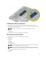
Removing the Memory Module(s).................................................................................................. 24
Installing the Memory Module(s).................................................................................................... 25
Removing the System Board...........................................................................................................25
Installing the System Board.............................................................................................................27

Removing the Keyboard..................................................................................................................27
Installing the Keyboard................................................................................................................... 29
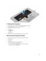
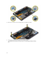
Removing the Display Assembly ....................................................................................................29
Installing the Display Assembly.......................................................................................................31
Removing the Palmrest Assembly.................................................................................................. 32
Installing the Palmrest Assembly.................................................................................................... 33
3 System Setup........................................................................................................ 35
Boot Sequence................................................................................................................................35
Navigation Keys...............................................................................................................................35
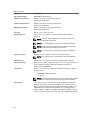
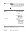
System Setup Options.....................................................................................................................36
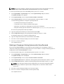
Updating the BIOS ......................................................................................................................... 40
System and Setup Password...........................................................................................................40
Assigning a System Password and Setup Password................................................................. 40
Deleting or Changing an Existing System and/or Setup Password.......................................... 41
4 Diagnostics........................................................................................................... 43
Enhanced Pre-Boot System Assessment (ePSA) Diagnostics........................................................ 43
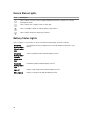
Device Status Lights........................................................................................................................44
Battery Status Lights....................................................................................................................... 44
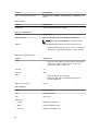
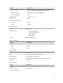
5 Technical Specifications.....................................................................................45
6 Contacting Dell.....................................................................................................51

1
Working on Your Computer
Before Working Inside Your Computer
Use the following safety guidelines to help protect your computer from potential damage and to help to
ensure your personal safety. Unless otherwise noted, each procedure included in this document
assumes that the following conditions exist:
• You have read the safety information that shipped with your computer.
• A component can be replaced or--if purchased separately--installed by performing the removal
procedure in reverse order.
WARNING: Before working inside your computer, read the safety information that shipped with
your computer. For additional safety best practices information, see the Regulatory Compliance
Homepage at www.dell.com/regulatory_compliance
CAUTION: Many repairs may only be done by a certified service technician. You should only
perform troubleshooting and simple repairs as authorized in your product documentation, or as
directed by the online or telephone service and support team. Damage due to servicing that is not
authorized by Dell is not covered by your warranty. Read and follow the safety instructions that
came with the product.
CAUTION: To avoid electrostatic discharge, ground yourself by using a wrist grounding strap or
by periodically touching an unpainted metal surface, such as a connector on the back of the
computer.
CAUTION: Handle components and cards with care. Do not touch the components or contacts on
a card. Hold a card by its edges or by its metal mounting bracket. Hold a component such as a
processor by its edges, not by its pins.
CAUTION: When you disconnect a cable, pull on its connector or on its pull-tab, not on the cable
itself. Some cables have connectors with locking tabs; if you are disconnecting this type of cable,
press in on the locking tabs before you disconnect the cable. As you pull connectors apart, keep
them evenly aligned to avoid bending any connector pins. Also, before you connect a cable,
ensure that both connectors are correctly oriented and aligned.
NOTE: The color of your computer and certain components may appear differently than shown in
this document.
To avoid damaging your computer, perform the following steps before you begin working inside the
computer.
1. Ensure that your work surface is flat and clean to prevent the computer cover from being
scratched.
2. Turn off your computer (see Turning Off Your Computer).
3. If the computer is connected to a docking device (docked) such as the optional Media Base or
Battery Slice, undock it.
5

CAUTION: To disconnect a network cable, first unplug the cable from your computer and
then unplug the cable from the network device.
4. Disconnect all network cables from the computer.
5. Disconnect your computer and all attached devices from their electrical outlets.
6. Close the display and turn the computer upside-down on a flat work surface.
NOTE: To avoid damaging the system board, you must remove the main battery before you
service the computer.
7. Remove the main battery.
8. Turn the computer top-side up.
9. Open the display.
10. Press the power button to ground the system board.
CAUTION: To guard against electrical shock, always unplug your computer from the electrical
outlet before opening the display.
CAUTION: Before touching anything inside your computer, ground yourself by touching an
unpainted metal surface, such as the metal at the back of the computer. While you work,
periodically touch an unpainted metal surface to dissipate static electricity, which could harm
internal components.
11. Remove any installed ExpressCards or Smart Cards from the appropriate slots.
Turning Off Your Computer
CAUTION: To avoid losing data, save and close all open files and exit all open programs before you
turn off your computer.
1. Shut down the operating system:
– In Windows 8:
* Using a touch-enabled device:
a. Swipe in from the right edge of the screen, opening the Charms menu and select
Settings.
b. Select the and then select Shut down
* Using a mouse:
a. Point to upper-right corner of the screen and click Settings.
b. Click the and select Shut down.
– In Windows 7:
1. Click Start .
2. Click Shut Down.
or
1. Click Start .
6

2. Click the arrow in the lower-right corner of the Start menu as shown below, and then
click Shut Down..
2. Ensure that the computer and all attached devices are turned off. If your computer and attached
devices did not automatically turn off when you shut down your operating system, press and hold
the power button for about 4 seconds to turn them off.
After Working Inside Your Computer
After you complete any replacement procedure, ensure you connect any external devices, cards, and
cables before turning on your computer.
CAUTION: To avoid damage to the computer, use only the battery designed for this particular Dell
computer. Do not use batteries designed for other Dell computers.
1. Connect any external devices, such as a port replicator, battery slice, or media base, and replace
any cards, such as an ExpressCard.
2. Connect any telephone or network cables to your computer.
CAUTION: To connect a network cable, first plug the cable into the network device and then
plug it into the computer.
3. Replace the battery.
4. Connect your computer and all attached devices to their electrical outlets.
5. Turn on your computer.
7

8

2
Removing and Installing Components
This section provides detailed information on how to remove or install the components from your
computer.
Recommended Tools
The procedures in this document may require the following tools:
• Small flat-blade screwdriver
• #0 Phillips screwdriver
• #1 Phillips screwdriver
• T5 Torx screwdriver
• Small plastic scribe
• Flash BIOS update program CD
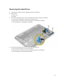
System Overview
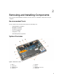
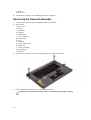
Figure 1. Inside View — Back
1. DC-in
2. system fan
3. system board
4. hard drive
5. speakers
6. battery
7. I/O board connector
8. I/O board
9

9. WLAN card
10. video-card fan
11. memory modules
12. heatsink
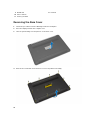
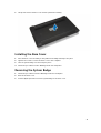
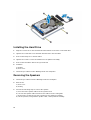
Removing the Base Cover
1. Follow the procedures in
Before Working Inside Your Computer
.
2. Close the display and turn the computer over.
3. Turn the system badge over and place it on the base cover.
4. Remove the screws that secure the base cover to the palmrest assembly.
10

5. Lift up and remove the base cover from the palmrest assembly.
Installing the Base Cover
1. Place the base-cover assembly on the palmrest assembly and snap it into place.
2. Tighten the screws to secure the base cover to the computer.
3. Turn the system badge over and snap it in place.
4. Follow the procedures in
After Working Inside Your Computer
.
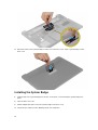
Removing the System Badge
1. Follow the procedures in
Before Working Inside Your Computer
.
2. Remove the base cover.
3. Peel the Mylar tape that secures the system badge to the base cover.
11

4. Release the tab on the system badge from the slot on the base cover. Lift the system badge off the
base cover.
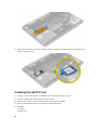
Installing the System Badge
1. Slide the tab on the system badge into the slot on the base cover and snap the system badge into
place.
2. Turn the base cover over.
3. Affix the Mylar tape that secures the system badge to the base cover.
4. Follow the procedures in
After Working Inside Your Computer.
12

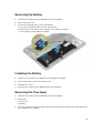
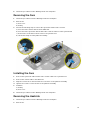
Removing the Battery
1. Follow the procedures in
Before Working Inside Your Computer
.
2. Remove the base cover.
3. Perform the following steps to remove the battery:
a) Disconnect the battery cable from the system board.
b) Remove the screws that secure the battery to the palmrest assembly.
c) Lift the battery off the palmrest assembly.
Installing the Battery
1. Tighten the screws that secure the battery to the palmrest assembly.
2. Connect the battery cable to the system board.
3. Install the base cover.
4. Follow the procedures in
After Working Inside Your Computer.
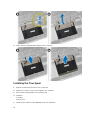
Removing the Touchpad
1. Follow the procedures in
Before Working Inside Your Computer
.
2. Remove the:
a) base cover
b) battery
3. Disconnect and remove the touchpad cable from the system board. Remove the screws that secure
the touchpad to the computer.
13

4. Slide out the touchpad and lift it away from the computer.
Installing the Touchpad
1. Align the touchpad in its position on the computer.
2. Tighten the screws to secure the touchpad to the computer.
3. Connect the touchpad cable to the system board.
4. Install the:
a) battery
b) base cover
5. Follow the procedures in
After Working Inside Your Computer
.
14

Removing the Hard Drive
1. Follow the procedures in
Before Working Inside Your Computer
.
2. Remove the:
a) base cover
b) battery
3. Perform the following steps to remove the hard drive from the palmrest assembly:
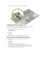
a) Disconnect the hard-drive cable from the system board.
b) Remove the screws that secure the hard drive to the palmrest assembly.
c) Lift the hard drive off the palmrest assembly.
4. Perform the following steps to remove the hard-drive bracket:
a) Disconnect the interposer from the hard drive
b) Remove the screws that secure the hard-drive bracket to the hard drive.
c) Lift the hard drive off the hard-drive bracket.
15

Installing the Hard Drive
1. Align the screw holes on the hard drive-bracket with the screw holes on the hard drive.
2. Tighten the screws that secure the hard-drive bracket to the hard drive.
3. Connect the interposer to the hard drive.
4. Tighten the screws to secure the hard drive to the palmrest assembly.
5. Connect the hard-drive cable to the system board.
6. Install the:
a) battery
b) base cover
7. Follow the procedures in
After Working Inside Your Computer.
Removing the Speakers
1. Follow the procedures in
Before Working Inside Your Computer
.
2. Remove the:
a) base cover
b) battery
3. Perform the following steps to remove the speaker:
a) Disconnect the speaker cable from the system board.
b) Unroute the speaker cable and remove the cable from the routing tabs.
c) Remove the screw that secures the speakers to the palmrest assembly.
d) Lift the speakers, along with the speaker cable, off the palmrest assembly.
16

Installing the Speakers
1. Align the speakers in the slot on the palmrest assembly.
2. Route the speaker cable through the routing tabs on the palmrest assembly.
3. Tighten the screw to secure the speakers to the palmrest assembly.
4. Connect the speaker cable to the system board.
5. Install the:
a) battery
b) base cover
6. Follow the procedures in
After Working Inside Your Computer
.
Removing the Wireless Local Area Network (WLAN) Card
1. Follow the procedures in
Before Working Inside Your Computer
.
2. Remove the:
a) base cover
b) battery
3. Perform the following steps to remove the WLAN card:
a) Remove the screw to release the bracket that secures the WLAN card to the computer.
b) Disconnect the antenna cables from the WLAN card.
c) Slide and remove the WLAN card from its connector on the I/O board.
17

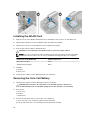
Installing the WLAN Card
1. Align the notch on the WLAN card with the tab on the WLAN-card connector on the I/O board.
2. Align the bracket which secures the WLAN card to the palmrest assembly.
3. Tighten the screw to secure the WLAN card to the palmrest assembly.
4. Connect the antenna cables to the WLAN card.
CAUTION: To avoid damage to the WLAN card, do not place any cables under it.
NOTE: The color of the antenna cables is visible near the tip of the cables. The following table
provides the antenna-cable color scheme for the WLAN card supported by your computer.
Connectors on the WLAN card Antenna-cable color
Main (white triangle) white
Auxiliary (black triangle) black
5. Install the:
a) battery
b) base cover
6. Follow the procedures in
After Working Inside Your Computer.
Removing the Coin-Cell Battery
1. Follow the procedures in
Before Working Inside Your Computer
.
CAUTION: Removing the coin-cell battery re-sets the BIOS settings to default. It is
recommended that you note the BIOS settings before removing the coin-cell battery.
2. Remove the:
a) base cover
b) battery
c) WLAN card
3. Perform the following steps to remove the coin-cell battery:
a) Disconnect the coin-cell battery cable from the I/O board.
b) Lift up and remove the coin-cell battery from the palmrest assembly.
18

Installing the Coin-Cell Battery
1. Replace the coin-cell battery in its slot in the computer.
2. Connect the coin-cell battery cable to the I/O board.
3. Install the:
a) WLAN card
b) battery
c) base cover
4. Follow the procedures in
After Working Inside Your Computer
.
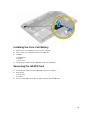
Removing the mSATA Card
1. Follow the procedures in
Before Working Inside Your Computer
.
2. Remove the:
a) base cover
b) battery
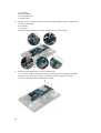
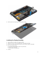
3. Disconnect the I/O-board cable from the system board and I/O board.
19

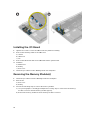
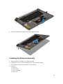
4. Remove the screw that secures the mSATA card to the palmrest assembly. Remove the mSATA card
from the system board.
Installing the mSATA Card
1. Align the notch on the mSATA card with the tab on the mSATA-card connector.
2. Insert the mSATA card into the mSATA-card connector.
3. Tighten the screw to secure the mSATA card to the palmrest assembly.
4. Connect the I/O-board cable to the system board and I/O board.
5. Install the:
a) battery
b) base cover
20
Page is loading ...
Page is loading ...
Page is loading ...
Page is loading ...
Page is loading ...
Page is loading ...
Page is loading ...
Page is loading ...
Page is loading ...
Page is loading ...
Page is loading ...
Page is loading ...
Page is loading ...
Page is loading ...
Page is loading ...
Page is loading ...
Page is loading ...
Page is loading ...
Page is loading ...
Page is loading ...
Page is loading ...
Page is loading ...
Page is loading ...
Page is loading ...
Page is loading ...
Page is loading ...
Page is loading ...
Page is loading ...
Page is loading ...
Page is loading ...
Page is loading ...
-
 1
1
-
 2
2
-
 3
3
-
 4
4
-
 5
5
-
 6
6
-
 7
7
-
 8
8
-
 9
9
-
 10
10
-
 11
11
-
 12
12
-
 13
13
-
 14
14
-
 15
15
-
 16
16
-
 17
17
-
 18
18
-
 19
19
-
 20
20
-
 21
21
-
 22
22
-
 23
23
-
 24
24
-
 25
25
-
 26
26
-
 27
27
-
 28
28
-
 29
29
-
 30
30
-
 31
31
-
 32
32
-
 33
33
-
 34
34
-
 35
35
-
 36
36
-
 37
37
-
 38
38
-
 39
39
-
 40
40
-
 41
41
-
 42
42
-
 43
43
-
 44
44
-
 45
45
-
 46
46
-
 47
47
-
 48
48
-
 49
49
-
 50
50
-
 51
51


Dell Vostro V 3800 Owner's manual
- Category
- Notebooks
- Type
- Owner's manual
- This manual is also suitable for
Ask a question and I''ll find the answer in the document
Finding information in a document is now easier with AI
Related papers
-
Dell M3800 Owner's manual
-
Dell M3800 Owner's manual
-
-
-
Dell Vostro 5470 Owner's manual
-
-
-
-
Dell Inspiron 5439 Owner's manual
-
Dell Precision 5520 Owner's manual