
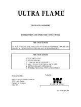
ULTRA FLAME
DIRECT VENT GAS STOVE
INSTALLATION AND OPERATING INSTRUCTIONS
FOR YOUR SAFETY
DO NOT STORE OR USE GASOLINE OR OTHER FLAMMABLE VAPOURS AND LIQUIDS IN THE
VICINITY OF THIS OR ANY OTHER APPLIANCE
FOR YOUR SAFETY
IF YOU SMELL GAS:
1. OPEN WINDOWS
2. TURN OFF MAIN GAS SUPPLY
3. DON'T TOUCH ELECTRICAL SWITCHES
4. EXTINGUISH ANY OPEN FLAME
5. IMMEDIATELY CALL YOUR GAS SUPPLIER
Manufactured by :
DROLET STOVES & FIREPLACES INC.
1700 Leon Harmel
Quebec, Qc (Canada)
G1N 4R9
Tested by :
WARNOCK HERSEY
Rev 07/96 45046A

2
TABLE OF CONTENTS :
TABLE OF CONTENTS : ........................................................................................... 2
GENERAL INFORMATION : .................................................................................... 3
WARNING .................................................................................................................. 4
SPECIFICATIONS : .................................................................................................... 5
TOP, FRONT AND SIDE VIEWS : ............................................................................ 6
INSTALLATION:
SAFETY NOTICE : ......................................................................................... 7
POSITIONING THE STOVE : ........................................................................ 7
VENT TERMINAL LOCATION : .................................................................. 7-8-9
CLEARANCES : ............................................................................................. 10
INSTALLATION OF THE UNIT : ................................................................. 10-11
VENTING KITS :
STRAIGHT OUT INSTALLATION ............................................................... 12
CORNER INSTALLATION: ........................................................................... 12-13
BASEMENT INSTALLATION: ..................................................................... 13
DISTANT INSTALLATION : ........................................................................ 15
VENTING SYSTEM : ................................................................................................. 16
VENT TERMINAL STRAIGHT OUT AND CORNER INSTALLATION: .............. 16-17
VENT TERMINAL, BASEMENT INSTALLATION: .............................................. 17
VENT TERMINAL, ROOF INSTALLATION : ......................................................... 18
INSTALLATION OF SIDE PANELS AND PEDESTAL .......................................... 18-19
GLASS FRONT REMOVAL, CLEANING AND INSTALLATION: ....................... 20
BURNER REMOVAL AND INSTALLATION ......................................................... 20
LOG INSTALLATION : .............................................................................................. 22
EMBER KIT INSTALLATION : ................................................................................ 23
REFRACTORY PANELS INSTALLATION: ............................................................ 24
GOLD TRIM INSTALLATION: ................................................................................. 24
OPERATING INSTRUCTIONS: ................................................................................ 25-26
MAINTENANCE INSTRUCTIONS ........................................................................... 27
OPTIONAL PARTS: ................................................................................................... 28
REPLACEMENT PARTS ........................................................................................... 28
LIMITED 5-YEAR WARRANTY .............................................................................. 29

3
GENERAL INFORMATION :
The ULTRA FLAME DIRECT VENT GAS STOVE is a high-efficiency free-standing gas
appliance with a maximum input rating of 30 000 Btu/h with natural gas or 26,000 Btu/h with
propane. It features a thermostatic modulating valve and a constant pilot. This means that the
flame will vary in height according to room temperature. The colder the ambient temperature the
larger the flames. The valve is also independent of any exterior electrical supply. Your appliance
will therefore continue to heat your house in the event of a power failure.
For increased efficiency, we have included a 140 CFM blower with speed control and thermo-
switch. Your fan will therefore turn itself on or off automatically, if you desire.
Read these instructions and consult your local building authorities before installing this
appliance. Install the unit and its venting system only as described in these instructions.
KEEP THESE INSTRUCTIONS FOR FUTURE REFERENCE
This gas stove has been tested by WARNOCK HERSEY according to the CAN-CGA-2.22M82_
INTERIM #41 and engineering buletin #68 for Canada and ANSI Z21,50, 50A, 50B for USA.
It is mobile home approved.
The unit can be installed in a range of altitude from 0 to 4 500 ft (0-1 370 m).
This appliance must be connected to a venting system.
Use only with Drolet direct vent kit, supplied by manufacturer.

4
WARNING
INSTALLATION SHOULD BE DONE BY A QUALIFIED INSTALLER.
DO NOT BURN WOOD OR ANY OTHER MATERIAL IN THIS APPLIANCE.
HOT WHEN IN OPERATION. KEEP CHILDREN, FURNITURE, CLOTHING AND
FLAMMABLE MATERIAL AWAY FROM THE APPLIANCE.
ADVISE ADULTS AND CHILDREN TO THE HAZARD OF HIGH SURFACE
TEMPERATURES AND THAT THEY SHOULD STAY AWAY TO AVOID BURNS OR
CLOTHING IGNITION.
YOUNG CHILDREN SHOULD BE SUPERVISED WHEN THEY ARE IN THE SAME
ROOM AS THE APPLIANCE.
THE APPLIANCE SHOULD BE INSPECTED BEFORE USE AND AT LEAST ANNUALLY
BY A QUALIFIED SERVICE PERSON. MORE FREQUENT CLEANING MAY BE
REQUIRED DUE TO EXCESSIVE LINT FROM CARPETING, BEDDING MATERIAL, ETC.
IT IS IMPERATIVE THAT THE CONTROL COMPARTMENTS, BURNERS AND
CIRCULATING AIR PASSAGEWAYS BE KEPT CLEAN.
DO NOT MODIFY THIS APPLIANCE.
THE OPENINGS IN THE GAS STOVE PEDESTAL SHOULD NEVER BE BLOCKED.
PROVIDE ADEQUATE ACCESSIBILITY CLEARANCES FOR SERVICING AND PROPER
OPERATION.

5
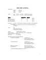
SPECIFICATIONS :
Dimensions :
height : 29-3/16"
width : 26-5/16"
depth : 19-5/8"
Glass : front 18-3/16" x 15-31/32" 1400
o
F clear ceramic
sides 5-1/16" x 15-31/32" 1400
o
F clear ceramic
Fuel : Natural Gas Propane
Input : 30 000 26 000 Btu/h
Manifold pressure : 3.5 10 in w.c.
Min inlet pressure : 5 11 in w.c.
Max. inlet pressure : 7 14 in w.c.
Vent size : 5" inner 8" outer coaxial vent pipes for straight out and corner kits
installation.
4" inner 8" outer coaxial vent pipes for basement or distant kit
installation
Valve : SIT
Model EUROSIT 630
Thermostatic modulating
Blower : Variable speed, 140 CFM
Thermo-switch : 120
o
F "ON", 90
o
F "OFF" bi-metal type,
Pressure relief device: Burst disc
Efficiency : 75 % heating
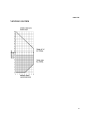
Maximum lenght of venting pipe allowed:
Straight out installation: - Vertical rise: 0’
- Max horizontal lenght: 5'
- Max combination of both: 5’
Corner installation: - Vertical rise: 0’
- Max horizontal lenght: 5'
- Max combination of both: 5’
Basement or distant - Max vertical rise: 25'
kit installation: - Max horizontal lenght: 10'
- Max combination of both: 25'
* Maximum number of elbows 90° or 45°: 3

6
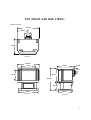
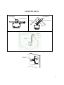
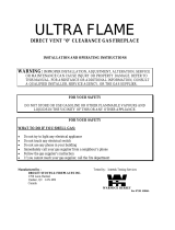
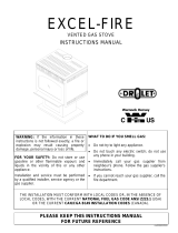
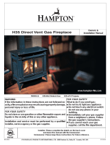
TOP, FRONT AND SIDE VIEWS :
INSTALLATION:
5"
26-5/16"
13-5/32"
8"
19-5/8"
Top view
13-5/8"
26-5/16"
17-1/2"
24-1/8"
Front view
19-5/8" 2-5/8"
6-1/8"
18-7/8"
29-3/16"
10-5/16"
18-1/4"
Side view

7
INSTALLATION
SAFETY NOTICE :
Improper installation may result in a house fire. Follow installation directions. Installation must
be in accordance with local building codes and with current CAN/CGA B149.1 & B149.2
installation codes for gas appliances.
INSTALLATION SHOULD BE DONE BY A QUALIFIED INSTALLER.
THIS GAS FIREPLACE MUST BE VENTED OUTSIDE.
The gas stove must be electrically grounded in accordance w ith the current CSA C22.1 Canadian
Electrical Code.
POSITIONING THE STOVE :
Always locate the stove as near as possible to an outside wall to keep vent length to a minimum.
Provide adequate accessibility clearances for servicing and proper operation. Never install the
stove in a hallway or near a staircase since it may block the way in case of a fire.
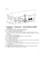
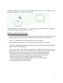
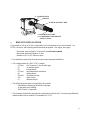
VENT TERMINAL LOCATION :
Your Ultra Flame stove vents through a vent terminal installed on the roof or on the outside of
any exterior wall of your house. Many restrictions apply to the vent terminal location that should
be considered before locating your stove.
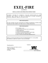
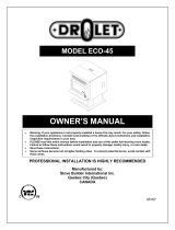
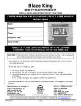
The following drawing presents a summary of most of these restrictions.

8
L9002.TIF
A = 12" Clearance above grade, veranda, porch, deck or balcony
B = 12" Clearance to window or door that may be opened
C = 12" Clearance to permanently closed window
D = 18" Vertical clearance to ventilated soffit located above the terminal within a horizontal
distance of 2 feet (60 cm) from the centre-line of terminal (straight out or corner
installation)
D = 24" (Basement or distant installation)
E = 12" Clearance to unventilated soffit (straight out or corner installation)
E = 24" (Basement or distant installation)
F = 12" Clearance to outside corner
G =12" Clearance to inside corner
H = Not to be installed above a meter/regulator assembly within 3 feet (90 cm) horizontally from
the centre-line of the regulator *
I = 72" Clearance to service regulator vent outlet
J = 12" Clearance to non-mechanical air supply inlet to building or the combustion air inlet to
any other appliance
K = 72" Clearance to a mechanical air supply inlet
L = 84"
Clearance above paved sidewalk or a paved driveway located on public property
M =36"
Clearance under veranda, porch, deck, or balcony

9
A vent shall not terminate directly above a sidewalk or paved driveway which
is located between two single family dwellings and serves both dwellings *
Only permitted if veranda, porch, deck, or balcony is fully open on a minimum
of 2 sides beneath the floor *
* As specified in CGA B149 Installation Codes (1991)
NOTE: Local codes or Regulations may require different clearances
In addition, the following restrictions also apply.
When the vent terminal is accessible, a certified guard shall be installed around the terminal. This
guard is available as an option, identified as part #E5480, for straight and corner terminals and
#E5482 for the basement terminal.
The vent terminal may not be recessed into the wall or siding.
The vent terminal shall not terminate :
- Within 3 ft. of a building mechanical air supply.
- Less than 12 inches from a perpendicular wall.
- In an area which is allocated to the occupancy.
- Under a window that pivots open.
In addition, in a structure with three walls and a roof , the following restrictions applies :
a) The minimum distance between the two side walls must be 72".
b) The roof must not exceed the walls more than 24".
c) If both those conditions applies, the clearance shall be as follow:
- 18" to a side wall.
- 12" to an unventilated soffit, 24" for basement or distant installation.
- 18" to a ventilated soffit, 24" for basement or distant installation.
CLEARANCES :

10
Clearance between the stove and any combustible material must also be respected while
installing your appliance. Clearance to the floor is 0".
Clearance between wall and the pipe is 1". Do not install pipe in an enclosed area or through an
insulated wall without a radiation shield ( no E-5710)
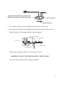
INSTALLATION OF THE UNIT
•
Move the ULTRA FLAME to the desired position. Mark the location for the gas inlet pipe
and the location where the vent pipes will go through the wall. Remove the appliance.
•
Route a 3/8" minimum NPT iron pipe gas line to the desired location.
•
Install a shutoff valve to the gas line. Tighten securely using a pipe joint compound.
•
Install a 1/8" NPT plugged tapping for test gauge connection immediately upstream of the gas
supply connection to the appliance.
•
If you wish to make a direct electrical connection to the blower without using the six-foot
cord supplied, route a 120 volt, 60 Hz electrical power supply line to the same location.
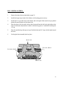
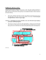
Remove the power cord and connect the 120V line as per the following procedure :
- Unscrew the speed control unit and pull a few inches away from the junction box
- Unscrew the two marr connectors attached to the cord (P) and the cord ground
- Remove the cord and route the supply line through the same holes
- Make the electrical connection with the same wires the cord was attached to
- Screw the ground wire to the junction box (G)
- Screw the speed control unit back in place

11
P
P
G
CONNECT THE POWER LINE TO THE SAME
WIRES THE CORD WAS CONNECTED TO (P)
SPEED CONTROL
JUNCTION BOX
•
If you prefer to use the six-foot cord supplied, just connect it to a 120V outlet.
•
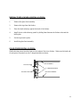
Move the ULTRA FLAME to the desired position and secure in place with four screws.
•
Connect the gas line to the stainless steel flex connector supplied.
FLEX CONNECTOR
SHUT OFF VALVE
PLUGGED TAPPING
STEEL GAS LINE
GAS VALVE
•
Check the gas line piping for leaks. Use a soap and water solution.
WARNING : DO NOT USE OPEN FLAME TO CHECK LEAKS.
•
You are now ready to proceed to the venting kit installation.

12
VENTING KITS
Once the position of the stove and the termination cap are fixed, you should select the venting kit
appropriate for your needs. First floor installations require either a STRAIGHT OUT kit or a
CORNER kit while basement installations must be done with a BASEMENT kit. Please note
that the BASEMENT kit can also be used on first (or higher) floors and it is possible to use up to
25' of pipe with a distant installation.
1) STRAIGHT OUT INSTALLATION:
- Make a 10-1/2" x 10-1/2" opening in the wall, 23-1/2" inches above the base of the
stove.
- Cut the radiation shield to lenght, if necessary and install as shown. Secure with
four # 10-1 wood screws.
- Install the vent pipe starting from the stove working your way out.
NOTE: All joints must be sealed with RTV silicone, 315°C. (600°F) temperature
resistance.
•
Fix the 5" rigid pipe on the stove with three tek screws and cut to leave a 2-1/2" projection
over the exterior wall.
•
Cut the 8" diameter pipe to be flush with outside face of exterior wall and fix it to the stove
with three tek screews throught the radiation shield.
•
Seal the pipe joints with silicone
•
The installation inside the house is now completed. The next step is to install the vent
termination cap following the instructions in the next section.
2) CORNER INSTALLATION:
- Make a 10-1\2" x10-1\2" opening in the wall 23-1\2" inches above the base of the
stove.
- Cut the radiation shield to lenght, if necessary, and install as shown. Secure with
four (4) #10-1" wood screws.
- Install the vent pipes starting from the stove working your way out.
NOTE: All joints must be sealed with RTV Silicone, 315°C (600°F) temperature
resistance.
•
Fix the 5" flexible pipe on the stove with locking band and seal with silicone cut to leave a 2-
1/2" projection over the exterior wall.
•
Slip on the 45° x 8" elbow.

13
•
Add a spring spacer. Spring spacer must be located opposite to the joints of the outside pipe
to prevent puncturing of the inside pipe when screwing two sections of the outside pipe
together.
•
Add sections of 8" diameter pipe and cut it to be flush with the outside face of exterior wall,
and install them to the 45° elbow, throught the radiation shield.
•
Seal the 8" diameter pipes and elbows joints with silicone.
•
The installation inside the house is now completed. The next step is to install the vent
termination cap following the instructions in the next section.
3) BASEMENT INSTALLATION:
- Make a 10-1\2" x10-1\2" opening in the wall to the desired position in the exterior wall.
- Cut the radiation shield to lenght, if necessary, and install as shown. Secure with four
(4) #10-1" wood screws.
- Install the vent pipes starting from the stove working your way out.
NOTE: All joints must be sealed with RTV silicone, 315°C (600°F) temperature resistance.
• Fix the reducer 5” to 4” with screws and seal with silicone.
•
Fix the 4" flexible pipe to the reducer with locking band and seal with silicone. Cut to leave
a 2-1/2" projection over the exterior wall.
•
Slip on the 90° elbow facing upward.
•
Add a spring spacer. Spring spacers must be located opposite to the joints of the outside
pipes to prevent puncturing of the inside pipe when screwing two sections of the outside pipe
together.
•
Add 8" diameter pipe sections, including the spring spacers, to attain the desired height.
Secure with screws.
•
Slip on the 90° elbow and horizontally the last section of 8" pipe. The pipe has to be cut to
be flush with outside face of exterior wall, them install it through the radiation shield.
•
Seal the 8"diameter pipes and elbows joints with silicone.
•
The installation inside the house is now completed. The next step is to install the vent
termination cap following the instructions in the next section.

14
VENTING KITS
Straight out
VENT TERMINAL
RADIATION SHIELD
-min 1"
-max 60"
Corner
VENT TERMINAL
45 ELBOW
O
60" MAX
RADIATION SHIELD
VENT PIPES
Basement
CUT TO LENGTH
10-1/2" X 10-1/2"
OPENING
.

15
5" LOCKING BAND
SCREWS
5" FLEXIBLE FLUE PIPE
8"RIGID AIR INLET PIPE
4" FOR BASEMENT OR DISTANT
INSTALLATION
4) DISTANT INSTALLATION
It is possible to use up to 25 feet of pipe and a wall vent terminal or roof vent terminal ( no
E5700 ) However, the following restrictions must be applied. (see figure, next page)
- Maximum vertical lenght is 10 feet with the wall vent terminal.
- Maximum horizontal lenght is 10 feet
- Number of 45° or 90° elbows is three
• For installation proceed in the same manner as the basement installation.
• The venting distant kit ( No E-5705 ) contain:
- (15 feet) of 4" diameter, 2 plys flexible pipe
- (1) 4" diameter union
- (2) locking bands
- (15 feet) high temperature insulation
- (6) spring spacers
- (24 feet) of aluminium tape
- (30) metal screws
- (1) radiation shield
• The following pieces must be supplied by the installer.
- Galvanized or black pipe minimum 24 gauges
- Appropriate roof flashing
- Roof braces ( if required )
• The clearance between the pipe and the combustible wall must be 2" from the pipe additional
radiation shield can be ordered. Part number is E-5710.

16
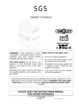
L9001.TIF
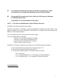
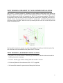
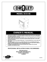
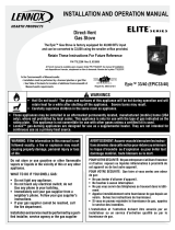
VENTING SYSTEM

17
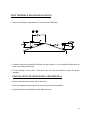
VENT TERMINAL STRAIGHT OUT AND CORNER INSTALLATION
Seal with RTV silicone between 8" diameter pipe and radiation shield inside and outside the
building to prevent air passage. Install the vent terminal as shown. Insert the wall plate inside
the 8" pipe and screw it to the wall using the six #10 2-1/2" wood screws supplied. Place the 5"
locking band around the inner connector and insert the exhaust pipe. Sealing the joint with RTV
silicone. Secure the pipe in place with one #10 1/2" metal screw. Install the casing and secure
with metal screws provided. Install the cover by inserting the tab in the slot on the wall plate and
secure with metal screws.
Seal around the terminal to prevent any water from leaking into the house. Seal both ends of the
slot where the cover was inserted in wall plate with RTV silicone.
VENT TERMINAL, BASEMENT INSTALLATION
• Seal with RTV silicone between 8" diameter pipe and radiation shield inside and outside the
building to prevent air passage.
• Fix the 4" flexible, pipe with the locking band and with RTV silicone.
• Fix the wall plate with 4 wood screws # 10 x 2-1\2" (supplied)
• Seal around the terminal to prevent water leakage into the house

18
VENT TERMINAL, ROOF INSTALLATION
• Here are the distance requirements for roof terminal installation.
• Clearance between combustible wall and vent pipe must be 2" and a radiation shield must be
use to cross and insulated wall.
• If vent terminal is more then 5 feet above the roof use roof braces to secure the whole
assembly
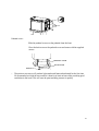
INSTALLATION OF SIDE PANELS AND PEDESTAL
• Remove the three nuts on each side of the stove.
• Place both panels in position and only screw the nuts back on manually.
• Align the panels with the gold trim and tighten all nuts.

19
NUTS
Pedestal cover :
Slide the pedestal cover over the pedestal from the front.
Place the back cover on the pedestal cover and secure with the supplied
screws.
SCREWS
BACK COVER
PEDESTAL COVER
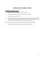
•
The paint on your stove will produce light smoke and fumes when heated for the first time.
We recommend you light the stove and let it burn for at least an hour while providing good
ventilation in the room. This will cure the paint and help preserve its quality.

20
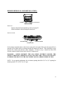
GLASS FRONT REMOVAL, CLEANING AND INSTALLATION
DECORATIVE
GOLD TRIMS
GLASS FRONT ASSEMBLY
CLAMPS
SIDE PANELS
(OPEN POSITION)
Removal :
- Let the stove cool down for at least one hour.
- Remove the decorative gold trim from the stove.
- Open both side panels.
- Open the four clamps.
- Remove the glass front assembly.
CAUTION : Do not operate your fireplace without a glass front or with a broken glass.
Cleaning :
- Only clean the glass when cold.
- Clean with liquid type cleaners or soap and water; do not use abrasive cleaners,
which can scratch the glass.
Installation :
- Put the glass front assembly back in position.
- Insert the hooks of all four clamps in the glass front slots.
- Tighten both top clamps simultaneously.
- Tighten both bottom clamps simultaneously.
- Close the side panels and install both decorative trim pieces.
Page is loading ...
Page is loading ...
Page is loading ...
Page is loading ...
Page is loading ...
Page is loading ...
Page is loading ...
Page is loading ...
Page is loading ...
-
 1
1
-
 2
2
-
 3
3
-
 4
4
-
 5
5
-
 6
6
-
 7
7
-
 8
8
-
 9
9
-
 10
10
-
 11
11
-
 12
12
-
 13
13
-
 14
14
-
 15
15
-
 16
16
-
 17
17
-
 18
18
-
 19
19
-
 20
20
-
 21
21
-
 22
22
-
 23
23
-
 24
24
-
 25
25
-
 26
26
-
 27
27
-
 28
28
-
 29
29


Ask a question and I''ll find the answer in the document
Finding information in a document is now easier with AI
Related papers
-
 Drolet ULTRA-FLAME GAS INSERT User manual
-
 Drolet ULTRA-FLAME GAS STOVE User manual
-
 Drolet Nova 820 User manual
-
 Drolet EXEL-FIRE User manual
-
 Drolet Nova 820 User manual
-
Drolet ECO-45 User manual
-
 Drolet Nova 820 User manual
-
 Drolet SIT 0.820.633 User manual
-
 Drolet ECO-45 PELLET STOVE User manual
-
 Drolet ECO-35 User manual


Other documents
-
 Regency Fireplace Products Ultimate U39 Owner's manual
-
Regency U39-NG1 User manual
-
 Regency Fireplace Products H35 Owner's manual
-
 Blaze King 6003 E SIT V1.08 Owner's manual
-
 Lennox Hearth EPIC40 User manual
-
Waterford Appliances E65-LP1 User manual
-
Sherwood EG 28 Direct Vent User manual
-
 Regency Fireplace Products U39-LP User manual
-
Comfort Glow Comfort Glow CHDV34PA User manual
-
Enviro 828 MH User manual


