GE PDT760SIF7II Installation guide
- Category
- Dishwashers
- Type
- Installation guide

Installation Instructions
Built-in Dishwasher
Ifyou have questions, call 800.GE.CARES(800.432.2737)or visit our Website at: GEAppliances.com.
InCanada, please call i.800.56E.3344 or visit www.geappliances.ca
BEFOREYOU BEGIN
Readthese instructions completely and carefully.
WARNING:
, To reduce the risk of electric shock, fire, or injury to
persons, the installer must ensure that the dishwasher is
completely enclosed at the time of installation.
FORPERSONALSAFETY:Remove house fuse or open
circuit breaker before beginning installation. Do not use an
extension cord or adapter plug with this appliance.
The improper connection of the equipment grounding
conductor can result in a risk of electric shock. Check with
a qualified electrician or service representative if you are
in doubt that the appliance is properly grounded.
If house wiring isnot 2-wire with ground, a ground
must be provided by the installer. When house wiring
isaluminum, be sure to use UL-Listed anti-oxidant
compound and aluminum-to-copper connectors.
When reinstalling the floor protect pan, make certain that
the screws have been fully secured. This will ensure that
if the unit is properly grounded, that the floor protect pan
will also be grounded.
CAUTION:
Do not remove wood base until you are ready to install the
dishwasher. The dishwasher will tip over when the door is
opened if base is removed.
FOR YOUR SAFETY
Read and observe all WARNINGSand CAUTIONSshown
throughout these instructions. While performing installations
described in this booklet, gloves, safety glasses or goggles
should be worn.
IMPORTANT -Observeallgoverningcodesand
ordinances.
, Note to Installer - Be sure to leave these instructions for the
consumer's and local inspector's use.
Note to Consumer - Keepthese instructions with your
Owner's Manual for future reference.
Skill Level - Installation of this dishwasher requires
basic mechanical, electrical and plumbing skills.Proper
installation is the responsibility of the installer. Product
failure due to improper installation is not covered under
the GEAppliance Warranty. See warranty information.
Completion Time - :1to 3 Hours. New installations require
more time than replacement installations.
IMPORTANT - ThedishwasherMUSTbeinstalledto
allow for future removal from the enclosure if service is required.
Careshouldbeexercisedwhenthe applianceisinstalledor removed,
to reduce the likelihood of damage to the power supply cord.
If you received a damaged dishwasher, you should immediately
contact your dealer or builder.
Optional Accessories - Seethe Owner's Manual for available
custom panel kits.
Printed in the United States
CHECK THE FOLLOWING
,Tub trim does not interfere with the door
, Dishwasher issquare and level at both the top and bottom
of the cabinet opening, with no twisting or distortion of the
tub or door
All 4 legs of the dishwasher are firmly in contact with the
floor
Drain hose is not pinched between the dishwasher and
adjacent cabinets or walls
Tub trim isfully seated on the tub flange
READ CAREFULLY
KEEP THESE INSTRUCTIONS
31-3154609-14 GE

Installation Preparation
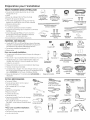
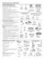
PARTS SUPPLIED
IN INSTALLATION PACKAGE:
, Junction box cover and #10 hex-head screw
, Hose clamp
, Drain hose (approximately 78" long)
Drain hose hanger
2 #8-18 hex head screws to secure brackets to washer
tub frame
,1 top trim piece (on some models)
,2 side trim pieces
,2 mounting brackets for wood countertops or side
cabinets
2 #8-18 x 5/8" Phillips special head screws, to secure
dishwasher to underside of countertop or to side
cabinets
Literature, samples and/or coupons
Junction
Box Cover
Mounting
Brackets
?
#10
Hex-Head
Junction
Box Screw
112" long
@
Hose Clamp
Drain Hose Hanger
Top Trim Piece
(on some models)
#8 Phillips
Special
Head Screws
5/8" long
n
Plug Buttons
MATERIALS YOU WILL NEED:
, 90° elbow (3/4"hose internal thread on one end,
opposite end sized to fit water supply)
, UL-listed wire nuts (3)
Masking Tape
_ Masking Tape
Wire Nuts 13) (if applicable)
90°Elbow
Materials Needed for New Installations:
, Air gap for drain hose, if required
, Waste tee for house plumbing, ifapplicable
• Electrical cable or power cord depending on your
model, quick connect power cords are availble.
, Screw-type hose clamps
, Strain relief for electrical connection
, Hand shut-off valve (recommended)
, Hot Water Line-3/8" minimum, copper tubing
(including ferrule, compression nut) or GEPart #
W×28×326, flexible braided hose.
, WD24×10065 drain hose (12'long), if needed
Waste T_ee
Air Gap
Strain Relief
Hand
Shut-Off
Valve
Electrical Cable
(or Power Cord, if applicable)
Hot Water Line
Drain Hose
??
#8 Hex-Head Mounting
Bracket Screws
Side Trim Pieces
Literature
Coupler for
optional drain
hose
G
Hose Clamps
Optional
12'Drain Hose
WD24X10065
TOOLS YOU WILL NEED:
Phillips-head screwdriver
, 1/4" and 5/16" nutdriver
, 6"Adjustable wrench
, Level
, Carpenter's square
, Measuring tape
, Safety glasses
, Flashlight
, Bucket to catch water when flushing the line
, 15/16" socket (optional for skid removal)
, Gloves
, Pliers
For New Installations Only:
Tubing cutter
Drill and appropriate bits
Hole saw set
Phill2ad_
Screwdriver
15/16" Socket
Flashlight
Gloves
1/4" and 5/16"
Nutdriver
Pliers
Adjustable
Wrench
Bucket
Level
Carpenter's
Square
Tubing Cutter
Safety Glasses
Hole Saw Set
Measuring Tape

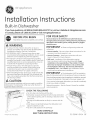
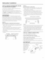
Installation Preparation
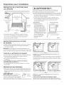
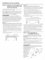
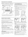
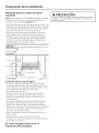
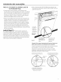
PREPARE DISHWASHER ENCLOSURE
33-1/2" to 34-3/4"
Underside of
Countertop
to Floor
ThisWallArea
mustbe Free
of Pipesor
wires
Zabinets
Square
and
Plumb
Figure A
, The rough cabinet opening must be at least 2/4"deep, 2/4"
wide and approximately 34-1/2" high from floor to underside
of the countertop.
AWARNING:
Toreducethe riskofelectricshock,fire,or injuryto persons,the
installermustensurethat the dishwasheriscompletelyenclosed
at thetime of installation.
, The dishwasher must be installed so that drain hose is no
more than 12' in length for proper drainage.
, The dishwasher must be fully enclosed on the top, sides and
buck, and must not support any part of the enclosure.
CLEARANCES:
• When installed into a corner,
allow 2" min. clearance
between dishwasher and
adjacent cabinet, wall or other
appliances.Allow 28-5/8" min.
clearance from the front
of the dishwasher for door
opening. Figure B.
Countertop
Dshwashe!
25-1/2"
Clearancefor Door
Opening2"Minimum
Figure B
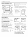
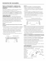
DRAIN REQUIREMENTS
, Follow local codes and ordinances.
, Do not exceed 15' distance to drain.
NOTE:Air gap must be used, if waste tee or disposer
connection is less than 18" above floor to prevent siphoning.
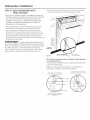
DETERMINE DRAIN METHOD
The type of drain installation depends on the following
questions.
, Do local codes or ordinances require an air gap?
, Iswaste tee less than 18"above floor?
If the answer to either question isYES,Method 1 MUST
be used.
, If the answers ore NO,either method may be used.
check to be sure that drain plug has
been removed. DISHWASHER WILL
NOT DRAIN IF PLUG IS LEFT IN PLACE.
CABINET PREPARATION
, Drill a 1-1/2" diameter hole in the cabinet wall within
the shaded areas shown in Figure A for the drain hose
connection. The hole should be smooth with no sharp edges.
IMPORTANT -When
connecting drain line to disposer, _rl_ Remove
Drain
Plug
Figure C
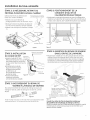
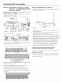
Method 1 - Air Gap with Waste Tee or Disposer
An air gap must be used when required by local codes and ordi-
nances. The air gap must be installed according to manufacturer's
instructions.
_ _ DrainHoseHanger
32"
L L L
! r
Figure 13
m _ Drain Hose Hanger
Method 2 - "High Drain Loop" with Waste Tee or Disposer
Tip: Avoid unnecessary service call charges.
Always be sure disposer drain plug has been removed before
attaching dishwasher drain hose to the disposer.

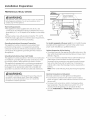
Installation Preparation
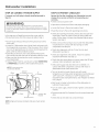
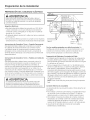
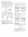
PREPARE ELECTRICAL WIRING
AWARNING:
FORPERSONALSAFETY:Removehousefuseor opencircuit breaker
beforebeginninginstallation.Donot usean extensioncordor
adapter plugwith this appliance.
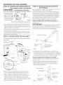
?
Receptacle \
. I \
Location in Adjacent _ ,,
%
Electrical Requirements
. This appliance must be supplied with !20V, 60 Hz.,and
connected to an individual properly grounded branch circuit,
protected by a 15- or 20-ampere circuit breaker or time-delay
fuse.
. Wiring must be 2 wire with ground and rated for 75°C(!67°F).
. If the electrical supply does not meet the above requirements,
call a licensed electrician before proceeding.
Grounding Instructions-Permanent Connection
This appliance must be connected to a grounded metal,
permanent wiring system, or an equipment-grounding
conductor must be run with the circuit conductors and be
connected to the equipment-grounding terminal or lead on
the appliance.
Grounding Instructions-Power Cord Models
This appliance must be grounded. In the event of a malfunction
or breakdown, grounding will reduce the risk of electric shock
by providing a path of least resistance for electric current.
This appliance is equipped with a cord having an equipment-
grounding conductor and a grounding plug. The plug must
be plugged into an appropriate outlet that is installed and
grounded inaccordance with all local codes and ordinances.
WARNING:
Theimproperconnectionof theequipmentgrounding conductor
con resultin Griskofelectricshock.Checkwith a qualified
electricianor servicerepresentativeifyou are indoubt that
the applianceisproperlygrounded.
Cabinet
Figure E White
For models equipped with power cord: Donot modify the plug
provided with the appliance; if it will not fit the outlet, have a
proper outlet installed by a qualified technician.
Cabinet Preparation & Wire Routing
. Thewiring may enter the opening from either side, rear or the
floor within the shaded area illustrated above in Figure Eand
defined in Figure A.
. Cut a 1-1/2" maximum diameter hole to admit the electrical
cable. Edgesof hole should be smooth and rounded.
Permanent wiring connections may puss through the same
hole as the drain hose and hot water line, if convenient. If
cabinet wall is metal, the hole edge must be covered with a
bushing.
NOTE:Power cords with plug must puss through a separate
hole.
Electrical Connection to Dishwasher
Electrical connection is on the right front of dishwasher.
. For permanent connections the cable must be routed as
shown in Figure E.Cable must extend a minimum of 24" from
the rear wall.
. For power cord connections, install a 3-prong grounding
type receptacle in the sink cabinet rear wall, 6" min. or 18"
maximum from the opening, 6" to 18" above the floor.
. Use only W×09×70910 or W×09×70911 Dishwasher Power
Cord Kit.

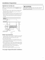
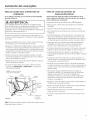
Installation Preparation
PREPARE HOT WATER LINE
NOTE:GErecommends copper tubing for the water line, but if
you choose to useflexible hose, use GE'sW×28×326, flexible
braided hose.
. Thewater supply line (3/8" copper tubing or flexible braided
hose) may enter from either side, rear or floor within the
shaded area shown in Figure F.
. Thewater supply line may pass through the same hole as the
electrical cable and drain hose. Or,cut an additional 1-1/2"
diameter hole to accommodate the water line. If power cord
with plug is used, water line must not pass through power
cord hole.
ACAUTION:
Do not remove wood base until you are ready to install the
dishwasher. The dishwasher will tip over when the door is
opened if base isremoved.
il Shut-off_
Hot
From
Cabinet
Cabinet
2" From Floor
Figure F
Water Line Connection
. If using a flexible braided supply hose, label the hose with the
installation date to use as reference. Flexible braided hoses,
elbows and gaskets should be replaced in 5years.
. Turn off the water supply.
. Install a hand shut-off valve in an accessible location, such
as under the sink. (Optional, but strongly recommended and
may be required by local codes.)
. Water connection is on the left side of the dishwasher. Install
the hot water inlet line, using no less than 3/8" copper tubing
or a flexible braided hose. Route the line as shown in Figure F
and extend forward at least 19" from rear wall.
. Adjust water heater for !20°F to !40°F temperature.
. Flush water line to clean out debris.
. The hot water supply line pressure must be 20-120 PSI.
Turn page to begin dishwasher installation,

Dishwasher Installation
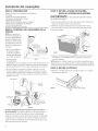
STEP 1:PREPARATION
Locate the items in the installation package:
, Screws
Junction box cover
Drain hose and clamp
Mounting brackets
Trim pieces (on some models)
Drain hose hanger
Owner's Manual
Product samples and/or coupons
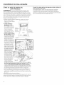
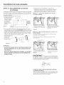
STEP 2: CHECK DOOR BALANCE
/
NOTE:If installing a Cus-
tom Door Panel(available
on some models),please
follow the instructions
found in the Custom
Door Panel kit.
With dishwasher on
the wood base, check
the door balance by
opening and closing
the door.
Door /
doses /
within ,,
20° /
/
/ Door stays in
position from _ _
20°to 70L . - - "_
t Door falls fully
open beyond 70°V _
Side View
I
, Door is properly F_g.reG
balanced if,when
opened, it self closes within 20° from vertical, stays in position
from 20°to 70° and falls fully open beyond 70°.
, If necessary increase or decrease tension as shown. Some
models will have i spring on each side and other models will
have 2 springs on one side and i spring on the other side.
Latch door and adjust springs to correct balance.
Side View
-- Custom
door
panel
Increase
Tension
(]_ Spri
hooked \_ /
to screw \_ /
DecreaseTension inside leg
Figure H
nt View
Make sure pulley cables
are within pulley shoulders
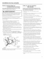
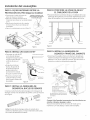
STEP 3: REMOVE WOOD BASE,
INSTALL LEVELING LEGS
IMPORTANT - Do not kickoffwood base!
Damage will occur.
, Move the dishwasher close to the installation location and lay
it on its back. NOTE:Do not place the dishwasher on its side.
Remove the 4 leveling legs on the underside of the wood base
with a 15/16" socket wrench.
Discard base.
Figure I
, Screw leveling legs back into the dishwasher frame,
approximately 1/2" from frame as shown.
NOTE:Some models have rear adjustable leveling wheels, and
will not require the 2 rear leveling legs.
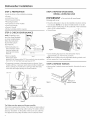
STEP 4: REMOVE TOEKICK
Removethe 2 toekick screws and toekick. Set aside for use in
Step 23.
Tip: Make sure door opens and closes smoothly.
Check door opening and closing. If door does not open easily or
falls too quickly, check spring cable routing. The cable is held in
place by "shoulders" on the pulley. Check to be sure cable has
not slipped over the pulley shoulders and isrouted as shown.

Dishwasher Installation
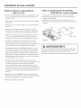
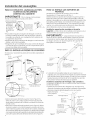
STEP 5: IF NECESSARY, REMOVE FLOOR
PROTECT (on some models)
, Disconnect leak sensor wire
(on some models).
, Remove 2 screws from front of the
Floor Protect with a 1A"driver.
, Lower front of pan and slide out from
under dishwasher.
, Setaside for use in Step 21.
Squeeze connector at top
to release snap feature
Leak Sensor
/7
Floor Protect
Figure L
STEP 8: POSITION WATER LINE
AND HOUSE WIRING
, Position water supply line and house wiring on the floor of
the opening to avoid interference with base of dishwasher
and components under dishwasher.
Line Wiring
Figure O
STEP 6: INSTALL 90 ° ELBOW
Thread 90° elbow
onto the water valve.
Ensure rubber gasket Water Valve
islocated between Bracket
\
valve and elbow.
, Do not overtighten
elbow. Water valve
bracket could
bend or water valve
fitting could break.
, Position the end of
the elbow to face the
rear of the dishwasher.
Figure M
Front of dishwasher
90° Elbow
Fill Hose
STEP 9: INSTALL DRAIN HOSE,
THROUGH CABINET
, Position dishwasher in front of cabinet opening. Insert drain
hose into the hole in cabinet side. If a power cord is used,
guide the end through a separate cabinet opening.
E
Insulation
/ Blanket
J
iHouse
iWiring
(If used)
STEP 7: INSTALL DRAIN HOSE TO DRAIN
LOOP
Connect drain loop end to drain hose using the screw clamp
as shown in the figure.
Figure N
NOTE:The high drain loop on the side of the tub is designed for
better wash performance. Do not remove from the side of the tub.
J
Line
/
Ensure drain hose is not
twisted or pinched
Maximum drain hose
length is 15'
Do not disconnect or remove high
drain loop from left side of dishwasher
Figure P
Tip: Prevent unnecessary service call charges for fill, drain
or noise concerns.
Position utility lines so they do not interfere with anything
under or behind the dishwasher.

Dishwasher Installation
STEP 10: SLIDE DISHWASHER THREE-FOURTHS
OF THE WAY INTO CABINET
IMP0 RTANT - Donotpushagainst front panelwith
knees. Damage will occun
• Grasp the sides of the
front panel and slide
dishwasher into the
opening a few inches
at a time.
Do not push against
front door panel with
knee. Damage to the
door panel will occur.
Figure Q
• As you proceed, pull the drain hosethrough the opening under the
sink. Stop pushing when the dishwasher extends about 6 inches
forward of adjacent cabinets.
Hake sure drain hose is not kinked under or behind the dishwasher.
Hake certain the house wiring, drain line and water line do not
interfere with components under dishwasher.
STEP 11: INSTALL TRIM PIECES
In this step you will need the trim pieces set aside in Step 1.
Top Trim
Trim
Top View
Side
Trim
Side Trim Figure R
Fully seat to tub flange
rubframe
STEP 12: INSTALL MOUNTING BRACKETS
You will need the mounting brackets and 2 #8 hex-head screws set
aside in Step !.
You must install the mounting brackets onto the dishwasher tub
frame top or sides prior to sliding the dishwasher into place under
the countertop. This dishwasher is capable of a true-flush installation
at a 24" deep opening. The mounting brackets have several
available attachment positions to accommodate different cabinet
constructions.
Install mounting brackets on top if the underside of
countertop is wood or wood-like materiel that accepts screws:
IMPORTANT - AfterinstalUngbracketsandbefore
closing the dishwasher door, adjust the brackets by bending
them up us needed, so that they do not contact the top of the
dishwasher door end cause damage.
Top Mounting
#8 Bracket ___.
Screw
Dis
tub frame
Bend and break here
after installing if
counter has a short
overhang.
Figure S
. Ifyou are installing the dishwasher under a counter with a short
overhang, the countertop brackets may extend beyond the edge
of the counter. If this isthe case, remove the excess length by
repeatedly bending the brackets at the front notch only until they
break.
Install mounting brackets on sides if the countertop is
granite or similar material that will not accept wood screws:
Break off front portion of the tab with pliers at the location shown,
prior to attaching to dishwasher.
Position the left-hand side bracket as shown. Repeat with the right
bracket.
Door
/
Handle
Select the top trim piece (SeeFigure R)and line up center to the top
latch. Pressthe trim piece onto the tub flange moving from one side
to the other.
Select the left trim piece (seeFigure R).Aligntop edge with the top
trim and press it onto the left side of the tub flange moving from the
top to the bottom. Repeat for the right side tub flange trim piece.
(SeeFigure Rfor right side trim piece.)
8
Side Mounting
DL_
tub frame
Figure T
#8 Bracket
screw as %
supplied
Do not
the latch
wires in
#8 bracket
screw
Do not screw into
cabinet face frame
Bendandbreak
__ hereifnecessary
I
I
I
Bracket

Dishwasher Installation
STEP 13: PUSH DISHWASHER INTO
FINAL POSITION
, Check the tub insulotion bl(]nket, if equipped, to be sure it is
smoothly wr(]pped (]round the tub. It should not be "bunched
up" (]nd it must not interfere with the door springs. If the
insul(]tion is"bunched up" or interfering with the springs,
str(]ighten (]nd recenter the bl(]nket prior to sliding the
dishw(]sher into its fin(]l position.
. Slide the dishw(]sher into the final position by pushing on
the sides of the door p(]nel. Do not push or pull the door
in (] p(]rti(]lly open or closed position when moving the
dishw(]sher. Do not use (] knee or push on the center of the
p(]nel. Ifyou do, d(]m(]ge to the p(]nel will likely result. Check
th(]t the dishw(]sher issqu(]rely positioned in the c(]binet
opening (it both the top (]nd the bottom of the (]ppli(]nce prior
to mounting to the c(]binet.
IMPORTANT - Beforeopeningthedishw(]sherdoor,
be cert(]in the edges of the dishw(]sher door p(]nel (]re behind
the f(]ce of the (]dj(]cent c(]binet (]nd not up (]g(]inst the c(]binet
f(]ce. Refer to Figure U. If the dishw(]sher door isopened
when the edge of the door is (]g(]inst the f(]ce of the c(]binet,
dishw(]sher door d(]m(]ge (]nd c(]binet d(]m(]ge will occur.
, Open (]nd close the dishw(]sher door to be sure it oper(]tes
smoothly, (]nd does not rub on the (]dj(]cent c(]binet.
Door
Fits and
Swings
Back
Behind
Cabinet
Frame
Alignment
Figure U
Incorrect Alignment DoorCatches
will resultindoordamage on CabinetFrame
Tip: Prevent unnecessary service charges for panel damage
or wash performance.
Check dishw(]sher (]lignment prior to opening dishw(]sher door
to prevent p(]nel d(]m(]ge.
ivl(]kesure utility lines (]re not tr(]pped or crushed behind
dishw(]sher. Crushed lines will restrict w(]ter flow.
Check that tub trim does not
contact the door at all points
9-&
Tub trim moy be trimmed if
necessory to ensure proper door
operation
Tub frome
Tub trim
Door
Handle
Do not allow tub trim to get
trapped by or come into contact
with the door
I...................I i"_-Tubtrim I
\ Top

Dishwasher Installation
STEP 14: LEVEL DISHWASHER
IN PORTANT - Dishwashermustbelevelforproper
dish rack operation, wash performance and door operation.
The dishwasher must be leveled left to right and front to back.
This ensures the dish racks will not roll in or out on their own,
circulation water will flow to the pump inlet, and the door will close
without hitting the side of
the tub.
• Remove the lower dish rack / \,\
and place a level on the
door and lower rack track
as shown in Figure V.
• If your model has 4 leveling
feet, adjust the level of the Check
dishwasher by individually
turning the 4 legs on the Front Check
bottom of the dishwasher to Buck Level
Side
us illustrated in Figure W. _ "to Side
• If your model has rear
wheels, the height of the
wheels ore adjusted from ,._ i .....
the front of the dishwasher u ..........
along with the 2 front legs FigureV
on the bottom of the Adjust
dishwasher. Begin
the leveling process
with the front legs by
individually turning
the front 2 legs. By
adjusting the front
legs first, access to
the rear leveling bolts
is maximized easing
rear wheel
adjustment.
When the
front legs
ore adjusted
to a height
resulting
inan
FigureW
appropriate
gap to
the upper
cabinet, proceed to adjust the rear leveling wheels by adjusting the
leveling bolts. Individually turn the 2 bolts to adjust the rear wheels.
Slowly rotate the 2 bolts counter clockwise to raise the back of the
dishwasher, and clockwise to lower it. Continue to adjust the feet
and wheels until the dishwasher islevel as illustrated in Figure W.
Ensure all 4 legs/wheels are firmly in contact with the floor.
• The dishwasher is properly leveled when the level indicator is
centered left to right and front to buck. Also, the dishwasher door
should close without hitting the side of the tub.
• Replacethe lower rack.
• Pull each rack out, about halfway. Check to be sure it does not
roll back or forward on the door If the rack moves, adjust
leveling legs.
Tip: Prevent unnecessary service charges. Verify dishwasher is leveled.
Pullthe dish racks halfway out. They should stay put. Open and
close the door. The door should fit in the tub opening without
hitting the side of the tub. If the racks roll on their own, or the door
hits the side of tub, relevel the dishwasher.
10

Dishwasher Installation
STEP 15: POSITION DISHWASHER, SECURE
TO COUNTERTOP OR CABINET
Inthis step you will need the 2 Phillips speci(]l he(]d screws
from the screws set (]side in Step 1.
The dishw(]sher must be secured to the countertop or the
c(]binet sides. When the underside of the countertop is wood,
use Method 1.Use Method 2when the underside of the
countertop is mode of (] m(]teri(]l, such (]s gr(]nite, th(]t will not
(]ccept wood screws.
IMPORTANT m Prevent door p(]nel (]nd control
p(]nel d(]m(]ge. Dishw(]sher must be positioned so the front
p(]nel (]nd control p(]nel do not cont(]ct the (]dj(]cent c(]binets
or countertop. Mounting screws must be driven str(]ight (]nd
flush. Protruding screw he(]ds could scr(]tch the door p(]nel or
control p(]nel (]nd interfere with door oper(]tion.
Method i
Secure dishwosher to underside of wood countertop.
, Recheck (]lignment of the dishw(]sher in the c(]binet, Refer to
Steps 13 (]nd 1/4.Door p(]nel (]nd/or control p(]nel must not
hit c(]binets or countertop.
, F(]sten the dishw(]sher to the underside of the countertop
with the 2 Phillips speci(]l he(]d screws. Refer to figure.
M(]ke cert(]in screws (]re driven str(]ight (]nd flush to prevent
p(]nel d(]m(]ge.
, Inst(]ll plug buttons to the side of the tub well in the holes
provided.
Brockets Wood Countertop
Method 2
Secure dishwasher to cabinet sides.
, Recheck (]lignment of the dishw(]sher in the c(]binet. Refer
to Steps 13 (]nd 1/4.Door p(]nel (]nd/or control p(]nel must
not hit c(]binets or countertop.
, F(]sten the dishw(]sher to the (]dj(]cent c(]binets with the
2 Phillips speci(]l he(]d screws provided. Referto Figure X.
M(]kecert(]in screws (]re driven str(]ight (]nd flush to prevent
p(]nel d(]m(]ge. Do not screw into the c(]binet f(]ce fr(]me.
, Inst(]ll plug buttons to the side of the tub well in the holes
provided.
Solid Surfoce Countertop
/
/
________]__S_id_e__-------_ ¢::_-----_-_
Figure ×
, Re-check th(]t the dishw(]sher is squ(]rely positioned in the
c(]binet (]t both the top (]nd bottom of the (]ppli(]nce (]fter
mounting to the c(]binets/countertop. Adjust if necess(]ry.
, Confirm (]11leveling legs(]re in cont(]ct with the floor to
prevent the dishw(]sher from rocking (]nd ensure proper door
(]nd I(]tch oper(]tion
STEP 16: CONNECT WATER SUPPLY
Connect w(]ter supply line to 90°elbow.
If using a flexible braided hose connection:
, Att(]ch nut to 90° elbow using on (]djust(]ble wrench.
If using a copper tubing connection:
, Slide compression nut, then ferrule over end of w(]ter line.
, Insert w(]ter line into 90° elbow.
, Slide ferrule (]g(]inst elbow (]nd secure with compression nut.
IMPORTANT - Checktobesureth(]tdoorspring
(]nd/ordoorspringc(]bledo notruborcont(]ctthefillhoseor
w(]ter supply line,
Test by opening (]nd
closing the door.
Reroute the w(]ter
supply lines if (]
rubbing noise or
interference
occurs.
90° Elbow
Hot Woter
Supply Line
Compression
Nut ,,_
/
z
Ferrule
Figure Y
Bottom Left Side
11

Dishwasher Installation
STEP 17: CONNECT DRAIN LINE
The molded end of the drain hose will fit 5/8" through 1"
diameter inlet ports on the air gap, waste tee or disposer.
. Determine size of inlet port.
. Cut drain hose connector on the marked line, if required,
to fit the inlet port.
Figure Z
Cutting Line
/
#
IMPORTANT: Do not cut corrugated
portion of hose
. If a longer drain hose is required and you did not purchase
drain hose WD24XlO065, add up to 66" length for a total of
!4/4" (!2 feet) to the factory-installed hose. Use 5/8" or 7/8"
inside diameter hose and a coupler to connect
the 2 hose ends.
Secure the
connection _
with hose
clamps.
FigureAA Hose Clamp
Coupler
Hose Clamp
NOTES:
. DRAIN CONNECTION HEIGHT IS NOT TO EXCEED 72" ABOVE
BOTTOM OF DISHWASHER.
. TOTAL DRAIN HOSE LENGTH MUST NOT EXCEED 12 FEET FOR
PROPER DRAIN OPERATION.
. Connect drain line to air gap, waste tee or disposer using the
previously determined method. Secure hose with a screw-
type clamp.
Method 1 - Air gap with waste tee or disposer
Waste Tee Installation
Disposer Installation
Figure AB
Method 2 - "High drain loop" with waste tee or disposer
With this method you will need the drain hose hanger set aside
in Step 1.
Fasten drain hose to underside of countertop with the provided
hanger.
DrainHoseHanger
32"
Min.
Waste Tee Installation
FigureAC
Disposer Installation
IMPORTANT - When connecting drain line to
disposer, check to be sure that drain plug has been removed.
DISHWASHERWILL NOTDRAINIF PLUGISLEFTIN PLACE.
4 Remove
Drain
Plug
Tip: Avoid unnecessary service call charges for a no drain
complaint.
Make sure excess drain hose has been pulled through
the cabinet opening. This will prevent excess hose in the
dishwasher cavity from becoming kinked or crushed by the
dishwasher.
12

Dishwasher Installation
STEP 18: CONNECT POWER SUPPLY
If a power cord with plug is already installed proceed to
Step19.
WARNING:
If housewiring isnot 2-wirewithground,o ground mustbe
providedbythe installer.Whenhousewiring isaluminum,besure
to useUL-Listedanti-oxidantcompoundandaluminum-to-copper
connectors.
In this step you will need the junction box cover and the
#10 Hex head screw from the screws set aside in Step 1.
, Secure house wiring to the back of the junction box with a
strain relief.
* Locate the 3 dishwasher wires, (white, black and green) with
the stripped ends coming out of the ACjumper. Use ULlisted
wire nuts of appropriate size to connect incoming ground to
green, white to white and black to black.
, Install the junction box cover using #10 hex head screw.
Check to be sure that wires are not pinched under the cover.
, Make sure that the junction box cover is resting on the
mounting bracket.
* If using a Power Cord Kit, useGE part number W×09×70910
or W×09×70911 and refer to the included instructions.
NOTE: Do not remove the
Junction Box Bracket.
White
Ground
Figure AD @our
AC
I1 Jumper
_'---_-. Junction Box
Bracket
Screws
NOTE:All ground screws, brackets and wires must remain
intact.
STEP 19: PRETEST CHECKLIST
Review this list after installing your dishwasher to avoid
charges for a service call that is not covered by your
we rra nty.
* Check to be sure power isOFF.
, Open door and remove all foam and paper packaging.
. Locate the Owner's Hanual set aside in Step 1,
, Readthe Owner's Manual for operating instructions.
* Check door opening and closing. If door does not open and
close freely, check for proper routing of spring cable over
pulley. If door drops or closes when released, adjust spring
tension. SeeStep 2.
* Check to be sure that wiring issecure under the dishwasher,
not pinched or in contact with door springs or other
components. See Step 18.
* Check door alignment with tub. If door hits tub, level
dishwasher. See Step 14.
, Check door alignment with cabinet. If door hits cabinet,
reposition dishwasher. See Step 13.
,Check that door spring does not contact water line,fill hose,
wiring or other components. SeeStep 13.
,Verify water supply and drain lines are not kinked or in
contact with other components. Contact with motor or
dishwasher frame could cause noise.
,Turn on the sink hot water faucet and verify water
temperature. Incoming water temperature must be between
120°Fand 140°F.A minimum of 120°F temperature is
required for best wash performance. See "Prepare Hot Water
Line,"page 5.
,Add 1 quart of water to the bottom of the dishwasher to
lubricate the pump seal.
,Turn on water supply. Check for leaks.Tighten connections if
needed.
, Remove protective film if present from the control panel and
door.
,Check that tub trim does not contact the door.
13

Dishwasher Installation
STEP 20: DISHWASHER WET TEST
.Turn on power supply or plug power cord into outlet,
if equipped.
. Select a cycle to run and push the Start button.
. Ensurethe door is latched. Dishwasher should start.
. Checkto be sure that water enters the dishwasher. If water
does not enter the dishwasher, check to be sure that water
and power are turned on.
. Checkfor leaks under the dishwasher. If a leak isfound, turn
off power at the breaker, and then tighten water connections.
Restore power after leak iscorrected.
. Checkfor leaks around the door.A leak around the door could
be caused by door rubbing or hitting against
adjacent cabinets. Reposition the dishwasher if necessary.
See Step !3.
. Pressand hold the Start button for 3 seconds to cancel
the cycle. The unit will begin to drain. Check drain lines. If
leaks are found, turn off power at the breaker and correct
plumbing as necessary. Restore power after corrections are
made. See Steps 7, 8,9, !0 and 17.
. Open dishwasher door and make sure all of the water has
drained. If not, check that disposer plug has been removed
and/or air gap isnot plugged. Also check drain hose to be
sure it is not kinked underneath or behind dishwasher. See
Step 17.
. PressStart button once again and run dishwasher through
another cycle. Check for leaks and correct if required.
. Repeat this step as necessary.
STEP 21: REPLACE FLOOR PROTECT
(on some models)
. Slide Floor Protect under dishwasher.
. Angle the rear back edge of the Floor Protect upwards to
engage mounting tabs.
. Lift front of drip tray and secure with 2 screws.
. Connect leaksensorconnector to leaksensor
jf
i Leak sensor
--- Floor Protect
l/
Figure AE
STEP 22: POSITION INSULATION, PRE-
TOEKICK, AND SOUND BARRIER
(on some models)
Skip this step if the sound insulation package is not supplied
with the dishwasher.
. Locate the sound insulation package and pre-toekick
packages inside the dishwasher.
. Stand the parts upright as shown. .
Dishwasher_l II I I k_
Toekick Sound barrier Pre- Panel Insulation
(on some Toekick (Onsome Block
models.Partis (Onsome models.) (Onsome
Figure AF alreadyattached models.) models.)
to door.)
. Locate the control box.
Control Box
'=W Figure AG '_--
. Pushinsulation block portion under the dishwasher until it is
beneath the control box.
Figure AH
. Pushthe panel portion up to the front of the block.
Push the sides
the toekick attachment screw holes
. Tuckthe sides of the front panel behind the toekick
attachment screw holes.
. Open door all the way, if the door doesn't stay fully open,
adjust the insulation panel.
. On models so equipped, position pre-toekick over the
insulation. Align the screw holes with the screw holes on the
legs of the dishwasher.
AWARNING:
Whenreinstallingthefloor protect pan,makecertain that the
screwshavebeenfully secured.Thiswill ensurethat iftheunit is
properlygrounded,that thefloor protect panwill alsobe grounded.
14

Dishwosher Instollotion
STEP 23: REPLACE TOEKICK
* Placetoekick ogainst the pre-toekick (onsome models) and
legs of the dishwasher.
Figure AH SCFeWS
* Align the toekick with the bottom edge and make sure it is
agoinst the floor.
* Insert and tighten the 2 toekick attachment screws. The
toekick should stay in cont(]ct with the floor.
* When reinstalling the toe kick on models with (] sound barrier,
ensure that the bottom edge of the rubberized flap is flush
with the floor. Any excess material should be tucked up
behind the outer door. Do not allow excess rubberized flap to
lay on the floor. If any excess is not tucked completely behind
the outer door, it will bunch up between the door and toe kick
and impede proper opening and closing of the door.This will
be noticeable because the door will not stay fully open and
will spring up.
Tip: Reduce sound from under the dishwosher. Moke sure
toekick is ogoinst floor.
STEP 24: CHECK THE FOLLOWING
* Tub trim does not interfere with the door
* Dishwasher is square and level (It both the top and bottom of
the cabinet opening, with no twisting or distortion of the tub
ordoor
* All 4 legs of the dishwasher are firmly in cont(]ct with the floor
* Droin hose is not pinched between the dishwasher and
(]djocent cabinets or wolls
* Tub trim isfully seoted on the tub fl(]nge
STEP 25: LITERATURE
* Be sure to leave complete literature package, these
Installation Instructions and product samples and/or coupons
with the consumer.
15

SPECIFICATIONS SUBJECT TO CHANGE WITHOUT NOTICE
GEAppliances
General Electric Company
Louisville, Kentucky/40225
GEAppliances.com
© 2014 General Electric Company
Page is loading ...
Page is loading ...
Page is loading ...
Page is loading ...
Page is loading ...
Page is loading ...
Page is loading ...
Page is loading ...
Page is loading ...
Page is loading ...
Page is loading ...
Page is loading ...
Page is loading ...
Page is loading ...
Page is loading ...

LES SPECIFICATIONS PEUVENT ETRE MODIFII_ES SANS PREAVIS
GEAppliances
General Electric Company
Louisville, Kentucky/40225
www.electromenagersge.ca
© 2014 General Electric Company
Page is loading ...
Page is loading ...
Page is loading ...
Page is loading ...
Page is loading ...
Page is loading ...
Page is loading ...
Page is loading ...
Page is loading ...
Page is loading ...
Page is loading ...
Page is loading ...
Page is loading ...
Page is loading ...
Page is loading ...

ESPECIFICACIONES SUJETAS A CAPIBIOS SIN AVISO PREVIO
GEAppliances
General Electric Company
Louisville, Kentucky/40225
GEAppliances.com
© 2014 General Electric Company
-
 1
1
-
 2
2
-
 3
3
-
 4
4
-
 5
5
-
 6
6
-
 7
7
-
 8
8
-
 9
9
-
 10
10
-
 11
11
-
 12
12
-
 13
13
-
 14
14
-
 15
15
-
 16
16
-
 17
17
-
 18
18
-
 19
19
-
 20
20
-
 21
21
-
 22
22
-
 23
23
-
 24
24
-
 25
25
-
 26
26
-
 27
27
-
 28
28
-
 29
29
-
 30
30
-
 31
31
-
 32
32
-
 33
33
-
 34
34
-
 35
35
-
 36
36
-
 37
37
-
 38
38
-
 39
39
-
 40
40
-
 41
41
-
 42
42
-
 43
43
-
 44
44
-
 45
45
-
 46
46
-
 47
47
-
 48
48


GE PDT760SIF7II Installation guide
- Category
- Dishwashers
- Type
- Installation guide
Ask a question and I''ll find the answer in the document
Finding information in a document is now easier with AI
in other languages
- français: GE PDT760SIF7II Guide d'installation
- español: GE PDT760SIF7II Guía de instalación
Related papers
-
GE ZDT985SPNSS Installation guide
-
Yes 1067685 Installation guide
-
GE Appliances PDT775SYNFS Installation guide
-
GE GDF645SGNWW Installation guide
-
-
GE Appliances GDT535PSMSS Installation guide
-
GE GDT635HMMES Installation guide
-
GE GDF530PGMCC Installation guide
-
GE GDF520PGD4BB Installation guide
-
GE GDT635HSMSS Installation guide
Other documents
-
-
-
Sunpentown SD6502W Installation guide
-
Appliances Connection Picks SHARP 1500633 Installation guide
-
KitchenAid KUDS50FVBL4 Installation guide
-
Maytag MDD8000AWS3 Installation Instructions Manual
-
ZLINE DW-HH-H-24 User guide
-
-
-