American Standard T415502.002 Installation guide
- Category
- Sanitary ware
- Type
- Installation guide

T415.50X
T420.50X
Series
PORTSMOUTH™
IN WALL PRESSURE BALANCING
BATH AND SHOWER TRIM KIT
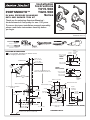
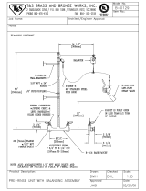
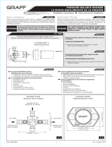
To assure proper positioning in relation to wall,
note roughing-in dimensions.
ROUGHING-IN DIMENSIONS
Certified to comply with ANSI A112.18.1
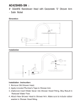
Installation
Instructions
Tubing Cutter
5/64"
Hex Wrench
Recommened Tools
Adjustable Wrench
Channel Locks
Flat Blade Screwdriver
Plumbers' Putty or Caulking
Phillips Screwdriver
Thank you for selecting American-Standard...
the benchmark of fine quality for over 100 years.
To ensure that your installation proceeds smoothly--
please read these instructions carefully before
you begin.
1-5/8" TO 3"
(41mm TO 76mm)
FINISHED WALL
4" (102 mm)
BOTTOM OF TUB
74" FOR HEAD CLEARANCE
(188 cm)
18" OPTIONAL
(45,7 cm)
5-1/8" REF.
(130 mm) REF.
1/2" NPT
(12,7 mm) NPT
7-5/8"
(195 mm)
7-13/16"
(198 mm)
OPTIONAL TO FINISHED FLOOR
USUALLY BETWEEN 65'' AND 78''
TOP OF TUB RIM
SHR
TUB
"SEE ILLUSTRATION"
T415 T420
H
C
216mm
(8-1/2")
REF.
125mm
(4-7/8")
REF.
1/2" COPPER
1-1/2" REF.
(38mm) REF.
INLETS 1/2" NPT
ESCUTCHEON T415
OUTLETS
1/2" NPT
3-3/8"
3-3/8"
6-1/2"
(165 mm)
ESCUTCHEON T420
7-5/8" DIA.
(195 mm)
0
1
2
3
4
5
6
THREADED INLETS (STOPS)
INLETS
1/2" NPT
5-7/8"
OUTLETS
1/2" NPT
3-3/8"
THREADED INLETS
SHR. 1/2" NOM.
COPPER SWEAT
TUB 1/2" NOM.
COPPER SWEAT
4-1/16"
5-7/8"
INLETS
4-1/16"
4-1/16"
INLETS
1/2" NOM.
COPPER
SWEAT
SHR. 1/2" NOM.
COPPER SWEAT
TUB 1/2" NOM.
COPPER SWEAT
2"
SWEAT
INLETS
SWEAT
INLETS (STOPS)
INLETS
1/2" NOM.
COPPER
SWEAT
C
o
l
d
Ho
t
M965028 REV.1.2

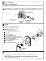
Align and install HANDLE (1) onto valve stem. Tighten
SET SCREW (2) using 2.5mm Hex Wrench supplied.
Check proper operation of HANDLE (1).
Turn on water supply on and test installed fitting.
Operate valve and diverter spout.
3
INSTALL HANDLE and TEST FITTING
HEX WRENCH
VALVE STEM
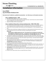
INSTALL TRIM (T415 & T420) - T415 illustrated
2
6
9
8
5
5
A
7
3
1
12
2
4
1
10
11
When finished tiling the wall, remove PLASTER GUARD (A)
and turn off water supply.
Push CAP (1) over VALVE CARTRIDGE (2).
Mount ESCUTCHEON (3) and gasket to valve body with SCREWS (4).
Press DIAL PLATE (11) onto CAP (1), flush against ESCUTCHEON (3).
Remove PIPE CAP & PLUG (5) from shower pipe and tub filler pipe.
Apply Teflon Tape to both ends of SHOWER ARM (6). Install SHOWER ARM (6)
with FLANGE (8) into shower pipe and tighten.
Thread SHOWER HEAD (7) onto ARM (6) and tighten.
Push SHOWER ARM FLANGE (8) to wall and tighten SET SCREW (9)
with 5/64” hex wrench.
Apply Teflon Tape to spout filler pipe and install SPOUT ESCUTCHEON (12)
and DIVERTER SPOUT (10).
CAUTION: Protect finish on SHOWER ARM,
SHOWER HEAD and TUB SPOUT when installing.
HEX
WRENCH
1
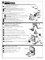
ROUGHING-IN
When soldering, remove PLASTER GUARD, CARTRIDGES and CHECK STOPS (IF PRESENT). When finished soldering,
flush valve body, replace cartridges, check stops (if present) and plaster guard to continue installation. Use thread
sealant or Teflon tape on threaded connections.
NOTE
COLD
HOT
1
7
5
3
6
4
2
See Roughing-in diagram before starting.
Connections are:
1/2" female NPT for threaded inlets.
Connect RISER PIPE (1) to MANIFOLD (2) top outlet marked "SHR".
Connect TUB FILLER PIPE (3) at bottom outlet marked "TUB".
For proper positioning the finished wall must be within side wall of
PLASTER GUARD
(4).
If the valve is installed on a fiberglass or other thin wall application,
the PLASTER GUARD
(4) can be used as a support.
Cut a 3" dia. hole in the shower stall.
Drill two additional 1" holes to allow access to the stops. (If applicable).
Remove PLASTER GUARD (4), rotate 90˚ so that indicated screw holes
fit MANIFOLD (2).
Push CAP on valve, place ESCUTCHEON on and attach with screws.
Connect hot and cold water supplies.
Cap off shower pipe (5) and tub filler pipe (6).
For support, use pipe BRACES (7) secured to wooden braces.
With valve turned off, turn on water supplies. Check for leaks
Cold
Hot
Cold
Hot
2
Turn off water at
main supply.
CAUTION
0
1
2
3
4
5
6
M965028 REV.1.2

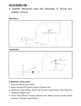
Loosen HANDLE SET SCREW (8) and pull of
HANDLE (2).
Pull off DIAL PLATE (9).
Remove two SCREWS (6) holding
ESCUTCHEON (7) and remove ESCUTCHEON (7).
Remove CAP (3), SCREWS (5) and CARTRIDGE (1).
Clean inlets and MANIFOLD (4).
Reassemble CARTRIDGE (1), alternately
tightening SCREWS (5).
Replace CAP (3), ESCUTCHEON (7),
DIAL PLATE (9) and HANDLE (2).
Check flow.
If faucet drips, operate handle several times
from "off" to "on". Do not apply excessive force.
Clogged CARTRIDGE (1) inlets may cause
reduced flow in "full on" hot or cold. To clean
inlets, first turn off water supply, then:
SERVICE
5
9
1
5
3
6
4
6
CARE INSTRUCTIONS
DO: SIMPLY RINSE THE PRODUCT CLEAN WITH CLEAR WATER. DRY WITH A SOFT COTTON
FLANNEL CLOTH.
DO NOT: CLEAN THE PRODUCT WITH SOAPS, ACID, POLISH, ABRASIVES, HARSH CLEANERS,
OR A CLOTH WITH A COARSE SURFACE.
HEX WRENCH
8
Cold
H
ot
7
"B"
"B"
4
ADJUST HOT LIMIT STOP
By restricting handle rotation and limiting the amount of hot water allowed to mix with the cold, the HOT LIMIT SAFETY STOP
reduces risk of accidental scalding. To set the maximum hot water temperature of your faucets, all you need to do is adjust
the setting on the HOT LIMIT SAFETY STOP.
Use a flat blade screwdriver or your fingers to pull up and rotate red HOT LIMIT SAFETY STOP (1). Follow Step "A" or "B"
to adjust min./max. discharge temperature. "0" being the hottest to "7" the coldest temperature setting. Factory set at "0".
HOT LIMIT SAFETY STOP ADJUSTMENT
PRY RED RING
FORWARD AND ROTATE
COUNTER-CLOCKWISE
ONE CLICK
PRY RED RING
FORWARD AND
ROTATE CLOCKWISE
"A"
"A"
ADJUSTMENT WHEN
WATER IS TOO HOT
ADJUSTMENT WHEN
WATER IS TOO COLD
"RED RING"- HOT
LIMIT SAFETY STOP
TEMPERATURE
SETTING
NUMBERS
1
0
1
2
3
4
5
6
CARTRIDGE
INLETS
2
M965028 REV.1.2
-
 1
1
-
 2
2
-
 3
3


American Standard T415502.002 Installation guide
- Category
- Sanitary ware
- Type
- Installation guide
Ask a question and I''ll find the answer in the document
Finding information in a document is now easier with AI
Related papers
-
American Standard T508.50X User manual
-
-
-
-
-
American Standard M968628 REV.1.3 User manual
-
-
-
-
American Standard T064507.002 User manual
Other documents
-
 MODONA AC42SH05-RB Installation guide
-
 MODONA AC42SH05-SN Installation guide
-
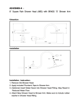 MODONA AC42SH05-A Operating instructions
-
 T & S Brass & Bronze Works B-0129 Datasheet
-
Design House 545756 Installation guide
-
Sigma 18.30.061 Installation guide
-
 SSI Fluid F1000B Installation Instructions Manual
-
Speakman S-2540 Installation guide
-
 Graff Faucets G-7005 Installation guide
-
 Sign of the Crab P0342 Installation guide


