Craftsman 10 IN. COMPOUND MITER SAW 315.23538 User manual
- Category
- Power tools
- Type
- User manual
This manual is also suitable for

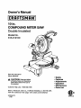
Owner's Manual
10 in.
COMPOUND MITER SAW
Double Insulated
Model No.
315.2121O0
Save this manual for
future reference
CAUTION: Read and follow
all Safety Rules and Operating
Instructions before first use of
this product,
Customer Help Line: 1-800-932-3188
Sears, Roebuck and Co., Hoffman Estates, IL 60179 USA
Visit the Craftsman web page: www.sears com/craftsman
972000-578
8-98
• Safety
• Features
• Adjustments
• Operation
• Maintenance
• Parts List
NRTL/C

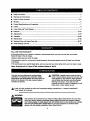
• Table of Contents........................................................................................................................................... 2
• Warranty and Introduction.............................................................................................................................. 2
• RulesFor Safe Operation ........................................................................................................................... 3-6
• Glossary......................................................................................................................................................... 6
• ProductSpecificationsand Unpacking .......................................................................................................... 7
• Labels............................................................................................................................................................. 8
• Loose Partsand Tools Needed...................................................................................................................... 9
• Features .................................................................................................................................................. 10-12
• Adjustments............................................................................................................................................. 13-19
• Operation................................................................................................................................................. 20-26
• Maintenance............................................................................................................................................ 27-28
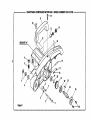
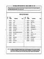
• ExplodedView and Repair PartsList...................................................................................................... 30-37
• PartsOrdedng/ Service ............................................................................................................................... 38
FULL ONE YEAR WARRANTY
Ifthis productfails due to a defect in material or workmanshipwithinone year from thedate of purchase,
Sears willrepair itfree of charge.
Contacta Sears Service Center for repair.
Ifthis productisused for commercialor rentalpurposes,thiswarrantyappliesonlyfor90 daysfrom the date
ofpurchase.
Thiswarrantygivesyou specificlegaldghts, and you may also have otherrightswhichvaryfrom state tostate.
Sears, Roebuck and Co., Dept. 817WA, Hoffman Estates, IL 60179
Yoursaw has many features for makingcuffing
operationsmore pleasant and enjoyable. Safety,
performanceand dependabilityhave been giventop
pdodtyihthe design ofthis saw makingit easy to
maintainand operate,
_IL CAUTION: Carefullyread throughthisentire
owner'smanual:beforeusingyournew saw.Pay
closeattentiontothe Rules ForSafe Operation,
and all Safety AlertSymbolsincludingDanger,
Warningand Caution. Ifyou use yoursaw
properlyand onlyfor what itisintended,you will
enjoyyears of safe, reliableservice.
,_ Look for this symbol to point out important safety precautions. It means attentionlH
Your safety is involved.
_lb WARNING:
The operationof any powertoolcan resultin foreignobjectsbeingthrownintoyoureyes,
whichcan result in severe eye damage. Beforebeginningpower tooloperation,always
wear safety gogglesor safety glasseswith side shieldsand a full face shield when needed.
We recommendWide _sion Safety Mask for useover eyeglassesor standardsafety
glasses with side shlel(Js,available at Sears Retail Stores.:
2

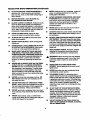
ThepurposeofsafetysymbolsIstoattractyourattention to possible dangers. The safety symbols, and
the explanations with them, deserve your careful attention and understanding. The safety warnings do
not by themselves eliminate any danger. The Instructions or warnings they give are not substitutes for
proper accident prevention measures.
SYMBOL
&
MEANING
SAFETY ALERT SYMBOL:
Indicatesdanger,warningor caution. •ey be used in conjunctionwith othersymbolsor picto-
graphs.
A
DANGER: Failuretoobey a safetywamingwill resultin sedous injurytoyoursefforto others.
Alwaysfollowthe safetyprecautionstoreducethe dsk oftire, electricshockand personalinjury.
A
WARNING: Failureto obey a safety waming can resultInsadous injurytoyourseffor to others.
Alwaysfollowthe safety precautionsto reducethe dskof fire,electdcshockand personal injury.
&
CAUTION: Failureto obey a safety wamingmay resultIn propertydamage or personal injuryto
yoursefforto others.Alwaysfollowthe safety precautionsto reducethe flskoffire,electricshock
and personal injury.
NOTE: Advisesyou of informationor instructionsvitaltothe operationor maintenanceof the equipment.
DOUBLE INSULATION
Doubleinsulationisa conceptinsafety, inelectric
powertools,whicheliminatesthe need forthe usual
thrae-wiragroundedpowercord.All exposedmetal
partsare isolatedfromintemal metalmotor
componentswith protectinginsulation.Double
insulatedtoolsdo not need to be grounded.
_k WARNING: Do notattempt to operate thistool
untilyou have read thoroughlyand understand
completelyall instructions,safety rules, etc.
contained inthis manual. Failureto complycan
resultin accidentsinvolvingfire, electdcshock,
or seriouspersonal injury.Save owner'smanual
and reviewfrequentlyforcontinuingsafe
operation,and instructingotherswho may use
thistool.
READ ALL INSTRUCTIONS
KNOW YOUR POWER TOOL. Read the owner's
manualcarefully. Learnthe saw's applications
and limitationsas well as the specificpotential
hazards relatedtothis tool
GUARD AGAINST ELECTRICAL SHOCK BY
PREVENTING BODY CONTACT WITH
GROUNDED SURFACES. Forexample; pipes,
radiators,ranges, refdgeratorenclosures.
KEEP GUARDS IN PLACE and ingood working
order.
REMOVE ADJUSTING KEYS AND
WRENCHES. Get in the habitofcheckingto see
that hexkeys and adjustingwrenchesare
removedfrom toolbeforefuming on saw.
IMPORTANT
Servicingrequiresextremecare and knowledgeofthe
systemand shouldbe performed onlybye qualified
sawica technician.Forservicewe suggestyou retum
thetooltoyournearest Sears storefor repair.Always
use odginalfactoryreplacementparts whenservicing.
KEEP THE WORK AREA CLEAN. Clutteredwork
areas and work benches inviteaccidents.DO
NOT leavetoolsor pieces ofwoodon the saw
whileit isin operation.
• DO NOT USE IN DANGEROUS ENVIRON-
MENTS. Do not usa powertoolsnear gasolineor
otherflammableliquids,in damp or wet locations,
or expose themto rain. Keep the work area well
lit.
KEEP CHILDREN AND VISITORS AWAY. All
visitorsshouldwear safety glasses and be kepta
safe distancefromwork area. Do not letvisitors
contact toolor extensioncordwhileoperating.
• MAKE WORKSHOP CHILD-PROOF with pad-
locksand masterswitches,or byremovingstarter
keys.
• DO NOT FORCE THE TOOl- Itwill do the job
better and safer at the ratefor whichit was
designed.
• USE THE RIGHT TOOL. Do notforce thetoolor
attachmentto do a jobit was not designedfor.
Don't use it fora purposenot intended.

RULES FOR SAFE OPERATION (Continued)
USE THE PROPER EXTENSION CORD. Make
sure yourextensioncordis in goodcondition.
When usingan extensioncord, be sureto use
one heavyenoughto carrythe currentyour
productwilldraw. An undersizedcord willcause
a drop in linevoltage resultingin lossof power
and overheating.A wire gage size (A,W.G.) of at
least14 is recommendedfor an extensioncord
25 feet or less in length.If in doubt,use the next
heaviergage. The smaller the gage number,the
heavierthe cord.
INSPECT EXTENSION CORDS PERIODI-
CALLY and replace ifdamaged.
DRESS PROPERLY. Do notwear loose clothing,
gloves, neckties,dngs, bracelets,or other
jewelry. They can get caughtand drew you into
movingparts. Rubberglovesand nonsliptoot-
wear are recommendedwhenworkingoutdoors.
Ais0 wear protectivehaircovedngto contain long
hair.
ALWAYS WEAR SAFETY GLASSES WITH
SIDE SHIELDS. Everydayeyeglasses haveonly
impact-resistantlenses;they are NOT safety
glasses.
PROTECT YOUR LUNGS. Wear a face or dust
maskif the cuttingoparetlon isdusty,
PROTECT YOUR HEARING. Wear headng
protectiondudngextended padods of oparetion.
SECURE WORK. Use clamps ora viseto hold
workwhen practical.I_ssafer than usingyour
hand and Itfrees bothhandsto operete tool.
DO NOT OVERREACH. Keep properfootingand
balanceat all times.
MAINTAIN TOOLS WITH CARE. Keeptools
sharpand clean for borer and saferpedor-
manca. Followinstructionsfor lubricatingand
changingaccassodes.
DISCONNECT ALL TOOLS. When not inuse,
before servicing,or when changingattachments,
blades, bits,cutters,etc., all toolsshouldbe
disconnected.
AVOID ACCIDENTAL STARTING. Be sure
switchis offwhen pluggingin.
USE RECOMMENDED ACCESSORIES. The
use of improperaccessoriesmay cause dskof
injury.
NEVER STAND ON TOOL. Sedousinjurycould
occurifthe tool istippedor ifthe blade isunln.-
tanUonailycontacted.
CHECK DAMAGED PARTS. Beforefurtheruse
ofthe tool, a guard or other part that is damaged
shouldbe carefullychecked todetermine that it
willoperate properlyand performitsintended
M
M
function. Check for alignmentof movingpads,
bindingof movingpart==,breakage ofparts,
mountingand any otherconditions that may
affect its operation.A guard or otherpart thatis
damaged mustbe propadyrepairedor replaced
by a qualifiedservice technicianat a Sears store
to avoiddskof personalinjury.
NEVER LEAVE TOOL RUNNING UNAT-
TENDED. TURN THE POWER OFF. Do not
leavetool untilitcomes to a completestop.
RRMLY CLAMP OR BOLT yourmiter sew to a
workbenchor table at approximatelyhipheight.
USE ONLY CORRECT BLADES. Do not use
blades with incorrectsize holes;Never use blade
washersor bladebolts that are defec_veor
incorrect.The maximumblade capacity ofyour
saw is 10 in.
KEEP BLADES CLEAN, SHARP AND WITH
SUFFICIENT SET. Sharpblades minimize
stallingand kickback.
DO NOT REMOVE THE SAW'S BLADE
I
GUARDS. Never operatethe sew with any guard
or coverremoved. Make sure all guardsare
operatingpropadybefore each use.
KEEP HANDS AWAY FROM CUTTING AREA.
Keep handsaway fromblades. Do not reach
underneathwork or aroundor underthe blade
while bladeis rotating. Do notattemptto remove
cut matedal when blade ismoving.
_1= WARNING: Bladecoastsafter turnoff.
M
M
M
DO NOT ABUSE CORD. Never yankcordto
disconnectitfrom receptacle. Keep cordfrom
heat, oil, and sharpedges.
INSPECT TOOL CORDS PERIODICALLY and if
damaged, have repairedby a qualifiedservice
technicianat a Sears store. Stay constantly
aware of cordlocationand keep itwell away
from the rotatingblade.
USE OUTDOOR EXTENSION CORDS. When
toolisused outdoors,use onlyextensioncords
with approvedgroundconnection that are
intendedfor useoutdoorsand somarked.
DO NOT USE TOOL IF SWITCH DOES NOT
TURN IT ON AND OFF. Have defectiveswitches
replacedby a qualifiedservicetechnicianat a
Sears store.
KEEP TOOL DRY, CLEAN, AND FREE FROM
OIL AND GREASE. Alwaysuse a clean cloth
when cleaning. Never usebrake fluids,gasoline,
petrolaum-basedproducts,or any solventsto
clean tool.
4

RULES FOR SAFE OPERATION (Continued)
ALWAYS SUPPORT LONG WORKPIECES to
minimizeriskof blade pinchingand kickback.
Saw may slip, walk, or slidewhilecuffinglongor
heavy boards.
BEFORE MAKING A CUT, BE SURE ALL
ADJUSTMENTS ARE SECURE.
GUARD AGAINST KICKBACK. Kickbackoccurs
when the blade stalls rapidlyand workplaceis
driven back towardsthe operator, itcan pullyour
hand intothe blade resultingin serious personal •
injury.Stay out of blade path and turnswitchoff
immediatelyif blade bindsor stalls. •
AVOID CUl'nNG NAILS. Inspectfor and
remove all nailsfromlumberbefore cutting.
ALWAYS USE A CLAMP to securethe work-
piece when possible.
NEVER TOUCH BLADE or othermovingparts
dudng use.
NEVER START A TOOL WHEN THE BLADE IS
IN CONTACT WITH WORKPIECE. Allow motor
to come up to fullspeed beforestartingcut.
MAKE SURE THE MITER TABLE AND SAW
ARM (BEVEL FUNCTION) ARE LOCKED IN
POSITION BEFORE OPERATING YOUR SAW.
Lock the mitertable bysecurelytighteningthe
miter lock handle. Lockthesaw arm (bevel
function)by securelytighteningthe bevel lock
knob.
NEVER USE A LENGTH STOP ON THE FREE
SCRAP END OF A CLAMPED WORKPIECE.
NEVER holdonto or bindthefree scrap end of
the workpiece in any operation.If a workclamp
and length stopare usedtogether,they must
bothbe installedon thesame side ofthe sew
table to preventthe sew fromcatchingthe loose
and and kickingup.
NEVER cut morethan one piece at aurae. DO
NOT STACK more than one workpleceon the
sew table at a time.
NEVER PERFORM ANY OPERATION "FREE-
HAND". Always place the workpiecato be cut on
the miter table and positionitfirmlyagainstthe
fence as a backstop.Always usethe fence.
NEVER hand holda workpiscathat istoo small
to be clamped. Keep handsclear ofthe no hands
zone.
NEVER reach behind,under,or withinthree
inchesofthe blade and itscuttingpath with your
handsand fingersfor any reason.
NEVER reach topickup a workpieca,a piece of
scrap, or any_ing else that is inor near the
cuttingpathofthe blade.
AVOID AWKWARD OPERATIONS AND HAND
POSITIONS where a sudden slipcouldcause
yourhandto moveintothe blade. ALWAYS
make sure you havegood balance. NEVER
operate yourmitersew on the flooror ina
crouchedposition.
NEVER standor have any part ofyourbodyin
linewiththe path ofthe sew blade.
ALWAYS release the powerswitchand allowthe
sew blade tostop rotatingbefore raisingit outof
the workpiece.
DO NOT TURN THE MOTOR SWITCH ON AND
OFF RAPIDLY. Thiscouldcause the sew blade
to loosenand could creata a hazard. Shouldthla
ever occur, standclear and allow the sew blade
to come to a completestop. Disconnectyoursew
from the powersupplyand securelyretlghtenthe
bladebolt.
REPLACEMENT PARTS. All repairs,whether
electricalor mechanical,shouldbe made by
qualifiedservice technicianat a Sears store.
,_ WARNING: When servicinguse onlyidentical
Craftsmanreplacementparts. Useof any other
parts may create a hazard or cause product
damage.
NEVER USE IN AN EXPLOSIVE ATMO-
SPHERE. Normalsparkingof the motorcould
Ignitefumes.
NEVER leavethe mitersew unattendedwhile
connected to a powersource.
POLARIZED PLUGS. To reducethe dskof
electdcshock_thistoolhasa polarizedplug (one
blade iswiderthanthe other). This plugwill fitin
a poladzed outletonlyone way. If the plugdoes
notfit fully in the outlet,reversethe plug.If itstill
does not fit,contacta qualifiedaiectdcian to
installthe properoutlat.Do notchange the plug
in any way.
IF ANY PART OF THIS MITER SAW IS MISS-
ING or shouldbreak, bend, orfail in any way, or
shouldany electricalcomponent fail toperform
properly,shutoffthe power switch,removethe
mitersaw plugfrom the powersourceand have
damaged, missing,or failedparts replaced
before resumingoperation.
DO NOT OPERATE THIS TOOL WHILE UN-
DER THE INFLUENCE OF DRUGS, ALCOHOL,
OR ANY MEDICATION.
5

RULES FOR SAFE OPERATION (Continued)
• ALWAYS STAY ALERT! Do not allowfamiliarity •
(gainedfrom frequent use ofyour saw)to cause
a careless mistake.ALWAYS REMEMBER that
a careless fraction ofa second issufficientto
inflictsevere injuPJ. •
ffi STAY ALERT AND EXERCISE CONTROL
Watch what you are doingand usecommon
sense. Do not operate tool when you are tired, ffi
Do not rush.
MAKE SURE THE WORK AREA HAS AMPLE
LIGHTING to see the workand that noobMtruc-
tionswillinterferewith safe operationBEFORE
performinganywork usingyoursaw.
ALWAYS TURN OFF SAW beforedisconnecting
it, to avoidaccidentalstartingwhen m-connect-
ing topowersupply.
SAVE THESE INSTRUCTIONS. Referto them
frequentlyand use toinstructotherusers.If you
loansomeonethis tool,loan them these instruc-
Miens also.
SAVE THESE INSTRUCTIONS
Arbor
The shafton which a blade or cuttingtoolis mounted.
Bevel Cut
A cuttingoperationmade withthe bladeat anyangle
otherthan 90"tothe mitertable,
Crosscut
Acuffingor shapingoperation madeacross the grain
ofthe workpiece.
Compound Miter Cut
A compoundmitercut isa cut made usinga miter
angle and a bevel angleat the same time.
Freehand
Performinga cutwithout usinga fence, mitergage,
fixture,work clamp, or other properdeviceto keepthe
workplecefromtwistingor movingdudngthe cut.
Gum
A sticky,sap based residuefrom woodproducts,
Mlter Cut
A cuttingoperationmade with the blade at any angle
otherthan 90"tothe fence.
Resin
A sticky,sap base substancethat has hardened.
Revolutions Per Minute (RP•)
The number ofturnscompleted bya spinningobject
inone minute.
Saw Blade Path
The area over, under, behind,or infrontofthe blade.
As it appliesto the workplece,thatarea whichwillbe,
or has been, cut bythe blade.
Set
The distancethatthe tip of the sawbledetoothis bent
(or set) outwardfrom the face ofthe blade.
I
Throw-Back
Throwing of a workplecein a mannersimilarto a
kickback.Usuallyassociatedwith a cause otherthan
the kerfdosing, suchas a workpiscenotbeing
against the fence, being droppedintothe blade, or
beingplaced inadvertentlyincontact withthe blade.
Through Sawing
Anycuttingoperationwhere the bladeextends
completelythrough the thicknessof the workplace.
Workplece
The item on whichthe cuffingoperationisbeing done.
The surfaces ofa workplecaare commonly referredto
as faces, ends, and edges.
Zero Clearance Throat Plate
A plasticthroatplate insertedIn the mitertable that
allowsfor bladeclearance. When:youmake yourfirst
cutwith yourcompound miter sew, the sew blade cuts
a slotthroughthe throat platethe exactwidth of the
blade. This providesfor a zeroclearance kerfthat
minimizesworkpiscataar-out.
No Hands Zone
The area betweenthe markedlinesonthe left and
dghtside ofthe mitertable base. Thiszone is
identifiedby no handszone labelsplacedinsidethe
markedlineson the mitertable base.

BladeDiameter 10in.
BladeArbor 5/8in.
NoLoadSpeed 5000RPM
Rating 120Volts,60Hz-ACOnly
Input 15Amperes
NetWeight 32Ibs.
CuttingCapacitywithMiterat0°/Bevel0°:
5-3/4in.Wx2-5/8in.T
MaximumCuttingCapacitywithMiterat45°/Bevel0°:
4-1/4in.Wx2-5/8in.T
MaximumCuttingCapacitywithMiterat0°/Bevel45°:
5-3/4in.Wx1-7/8in.T
MaximumCuttingCapacitywithMiterat45°/Bevel45°:
4-1/4in.Wx1-7/8in.T
YourCompoundMiterSawhasbeenshipped
completelyassembled exceptforthe blade, miterlock
handle,and dust guide.
_lb WARNING: Ifany parts are missing,do not
operate thistooluntilthe missingparts are
replaced. Failureto do socould resultin possible
serious porsonal injury.
• Remove all loose partsfrom the carton. Separate
and checkwith thelistoflooseparts.See Rgure 2.
• Remove the packingmaterialsfrom aroundyour
saw.
• Carefullyliftsaw from the cartonand place it on a
level work surface.Althoughsmall,this sew is
heavy.To avoid back injury,get helpwhen
needed.
Do not discardthe packingmaterialsuntilyou
havecarefully inspectedthe saw, identifiedall
looseparts,and setisfa_odly operated your new
saw.
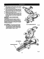
• Your saw has been shippedwiththe saw arm
lockedinthe down position. To release sew arm,
pushdownon top ofsaw arm and pullout the lock
pin. See Figure 4.
• Liftthe saw arm bythe handle.Hand pressure
shouldremain on the sew armto preventsudden
rise upon release ofthe lock pin.
• Examine all partsto make sure no breakageor
damage has occurreddudngshipping.
If any parts are damaged or missing,do notattemptto
plugin the power cord andturn the switchon untilthe
damaged or missingparts areobtainedand are
installedcorrectly.

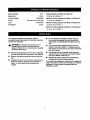
The followinglabelsare on the miter sawwith loca-
tionsindicated.
Restorelowerbladeguard
andsecurelytightenscrew
beforeuse
e.See
I
DANGER: DO NOT REMOVE I
ANY GUARD. USE OF SAW
WITHOUT THIS GUARD WILL
RESULT IN SERIOUS INJURY.
A WARNING/ ADVERTENCIA
• ForyourmfMy, madownersmanualbeforeop4rallng
ndtMHw.
• WmreyewOtocUo_
• KeepIvmdsoutofpareofmw blade.
• DonotoplmD HWwithoutguardsInplace.
• DonotWslmmzmyoperationI_Vam_.
• NevwnmchmmmdtheHW blade.
•Turn.oilt_l m_lwznformw bladetostopbefore
movingwodqdeceor©h_,_ng_mllngL
• Di.com_t thesawfromthepowersomcebefore
©hangingbladeorservicing.
• Donotexposetorainoruseindampplaces.
• ParasuNguddad, leaelmanualdelustmzloantes
deuMr I- sierraIngletadora.
10 inch Compound Miter Saw
emllUEIllEJffBI _ RIPllllm1_ MIIz J_MI,Y1$i
WARNING:WHeNSeJMCINO,useONLYI_,AL
CRAFTSMANREPLACEMENTPARTS.
MODEL 315.'_12100 S_R.. _
ASSEMBLEDINMmO¢O
SEARS,'/IOEBUCKANOOC_ I I
, Customer Help Line 1-800-932-3188
8
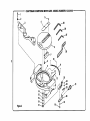
Rg. 1

ThefollowingitemsareincludedwithyourCompoundMiterSaw:
• Saw Blade- 10 in. • 5 mm Hex Key Wrench
• Miter LockHandle • 6 mm Hex Key Wrench
• DustGuide • 8mmHexKeyWrench
• BladeWrench • Owner's Manual
BLADEWRENCH
8 mmHEXKEY
6mmHEXKEY
p O
5 mmHEXKEY
MITERLOCKHANDLE
SAWBLADE
DUSTGUIDE
Fig.2
_i, WARNING: The useofattachmentsoreccessodes notIlstad mightbehazardousand could
cause serious personalinjury.
The followingtools(notincluded)are neededfor
checking adjustmentsofyoursaw or for
%Dinstallingthe blade:
FRAMINGSQUARE
17mmCOMBINATIONWRENCH
10mmCOMBINATIONWRENCH
PHILUPSSCREWDRIVER

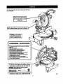
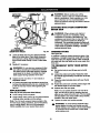
KNOW YOUR COMPOUND MITER
SAW
See Figure 3.
Beforeattemptingto use yoursaw, familiarizeyourself
withall operatingfeatures and safety requirements.
WARNING: Do not allowfamiliaritywith your
saw to make you careless. Remember that a
careless fractionof a secondissufficientto inflict
severe injury.
15 AMP MOTOR
Yoursaw has a powerful15 amp motorwithsufficient
powerto handle toughcuttingjobs. It ismade withall
ball beadngs,and has extemally accessiblebrushes
for ease of servicing.
10 in. BLADE
A 10 in.saw blade isincludedwithyourcompound
mitersaw. Itwillcut matedais up to2-5/8 in.thick or
5-3/4 in.wide, dependingupon the thickness of the
materialand the settingat whichthe cut isbeing
made.
SWITCH
L_K_LEVER
UPPER
BLADEGUAND
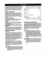
CUTTING CAPACITIES
When the miter angle (miter table) Is set at O° and
the bevel angle Is set at 0°:
Your saw will cut materials up to a maximum of
5-3/4 in. wide X 2-5/8 in.thick.
When the miter angle (miter table) Is set at 45° and
the bevel angle Is set at 0°:
Yoursaw willcut matsdalsup toa maximumof
4-1/4 in.wide X 2-5/8 in. thick.
When the miter angle (miter table) Is set at O° and
the bevel angle is set at 45°:
Your saw willcutmaterialsupto a maximumof
5-3/4 in.wide X 1-7/8 in.thick.
When the miter angle (miter table) Is set at 45° and
the bevel angle is set at 45°:
Your saw will cut materials up to a maximum of
4-1/4 in.wide X 1-7/8 in.thick.
SWITCHTRIGGER
DUSTGUIDE
BEVEL
LOCKKNOB
BLADEGUARD
MITERTABLE
)HANDS
ZONELABEL
"NOHANDSZONE"
ZEROCLEARANCE
'LATE
LOCKPLATE
CONTROLARM
Posmvz_oP(_
MITER .
LOCKHANDLE
Fig. 3
10

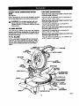
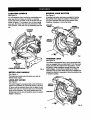
CARRYING HANDLE
Sea Figure4.
Forconveniencewhen carryingor transportingyour
miter sawfrom one placeto another, a carrying
handle hasbeen providedon top ofthe saw armas
showninfigure 4. To transport,turnoffand unplug
yoursaw, then lowerthe saw arm and lockit inthe
downposition.Locksaw arm by depressingthe lock
pin.
CARRYING
HANDLE
LOCK
PIN
SAW
ARM
MITERLOCK
HANDLE
SAWARM
LOCKEDINDOWNPOSITION
Fig. 4
MITER LOCK HANDLE
Sea Figure4.
The!miter lockhandle securelylocksyour saw at
desired miterangles.
LOCK-OFF LEVER
See Figure5.
The switchtdggaris equippedwith a lock-offlever to
reducethe possibilityof accidentalstarting.The lock-
offlever mustbe presseddownwiththe palm ofyour
handto tumsaw on. Once the saw ison, the lock-off
lever can be released, The spdng loadedlever will
spdngback intothe lock-offpositionwhen theswitch
tdggeris released.
11
SPINDLE LOCK BUTTON
See Figure5.
A spindlelock buttonhas been providedfor locking
the spindlewhichstopsthe rotationofthe blade in
yoursaw. Depress and holdthe lockbuttonwhile
installing,changing,or removingblade.
LOCK-OFF
SPINDLE
LOCKBuI"rON
SWITCH,
TRIGGER
Rg. L
TRIGGER LOCK
See Figure 6.
To prevent unauthodzedusaof yourcompoundmiter
saw, we suggestthat you disconnectitfromthe power
supplyand lockthe switchin the offposition.To lock
the switch,installa padlockthroughthe hole inthe
switchtdggar. A lockwith a shackleup to 13/64 in.
diameter may be used. When the lockisinstalledand
locked,the switch isinoperable.Store the padlock key
in another location.
SWITCH
TRIGGER
Fig. 6

POSITIVE STOPS ON MITER TABLE
Positivestopshave been providedst 0°, 22-1/2° and
45o.The 22-1/2° and 45° positivestopshave been
providedon boththe leftand rightside ofthe miter
table.
BEVEL LOCK KNOB
The bevel lookknobsecurelylocksyourcompound
mitersew at desired bevel angles. Positivestop
adjustmentscrewshave been providedon each side
ofthe sew arm. These adjustmentscrews are for
making fine adjustmentsat 0° and 45°. See pages 18
and 19.
ELECTRIC BRAKE
An aiectdc brake has been providedto quicklystop
blade rotationafterthe switchis released.
FENCE
The fence on yourcompoundmiter sew has been
providedtohold yourworkplecasecurelyagainst
when makingall cuts.
SELF-RETRACTING LOWER BLADE
GUARD
The lowerblade guard ismade of shock-resistant,
see-throughplasticthat providesprotectionfrom each
sideofthe blade. It retractsover the upper blade
guard as the saw islowered intothe workplace.
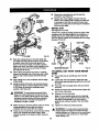
MOUNTING HOLES
See Figure 7.
Yourcompound miter saw shouldbe permanently
mounted to a firm supportingsurfacesuch as work-
bench.Four 7/16 in. boltholeshave been providedin
the saw base forthis purpose. Each ofthe four
mounting holesshouldbe boltedsecurelyusing7/16
in.machinebolts, lookwashers,and hex nuts(not
Included),Boltssh,ould be ofsufficientlengthto
accommodate the'saw base, lookwashers, hex nuts,
and thethicknessof the workbench.
Tightenall four bolts securely.
The holepatternfor an 18 in.x 24 in.workbenchis
shownin Figure7. Carefullycheckthe workbench
aftermounting to make surethat no movement can
occurduringuse. Ifany tipping,sliding,or walkingis
noted,secure the workbenchto theflour before
operating.
_l, WARNING: Always make sure yourcompound
mitersaw is securelymountedto a workbenchor
an approvedworkstand.Failureto do socould
resultin an accident resulting in possible sedous
personalinjury.
7/lr _.IIOLE 1?3/lr
I
1
31_31"
Fig. 7
ELECTRICAL CONNECTION
Yoursaw has a precisionbuiltaiectdc motor.It should
beconnected toa power supply that Is 120 volts,
60 Hz, AC only (normal household current). Do not
operatethis toolon directcurrent(DC). A substantial
voltagedropwillcause a lossofpowerand the motor
willoverheat. Ifyourtooldoes notoperate when
pluggedintoan outlet,double-checkthe power
supply.
j_ WARNING: The operationofany saw can
resultinforeignobjectsbeingthrownintoyour
eyes, whichcan resultin severseye damage.
Beforestartingpower tooloperation,always
wear safety gogglesor safety glasseswith side'
shieldsand a full face shieldwhen needed. We
recommendwide visionsafetymask for use over
eyeglasses or standardsafety glasseswith side
shields.
_1= WARNING: Do not attemptto modifythistool or
create acceesodesnot recommendedfor use
withthistool. Any suchalterationor modification
is misuseand could resultin a hazardous
condition leadingto possible sedouspersonal
injury.
12

_k WARNING: To preventaccidentalstartingthat
couldcause possiblesedouspersonalinjur/,
assemble all partsto yoursaw beforeconnecting
itto powersupply.Saw shouldnever be
connectedto power supplywhen you are
assemblingparts, makingadjustments,installing
or removingblades, orwhen not in use.
As mentionedpreviouslyyoursaw has been factory
assembled and adjusted.The miterlock handle,dust
guide, and blade are the only partsthathave to be
installed,
MITER LOCK HANDLE
See Figure 8.
To installthe miter lockhandle, place the threaded
stud on the end of the miter lockhandle intothe
threaded holein the control arm. Turn clockwiseto
tighten,
TIGHTEN
ARM
MITER MITER
LOCKHANDLE TABLE
Fig. 8
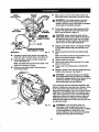
DUST GUIDE
See Figure 9.
To installthe dust guide, placethe end marked
INSERT over the exhaust port in the upperblade
guard.Turn the guide sothat the open end isfacing
downor towardthe rear ofthe saw.
EXHAUST
PORT
DUSTGUIDE
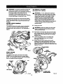
TO INSTALL BLADE
See Figures 10, 11, and 12.
A
WARNING: A 10 in. bladeisthe maximum
blade capacity ofyour saw. Never use a blade
that istoo thick to allowouterbladewasherto
engage withthe flats on the spindle.Larger
blades willcome in contact withthe blade
guards, whilethickerbladeswillpreventthe
bladescrewfrom secudngthe bladeon the
spindle. Eitherofthese situationscouldresultin
a sadous accident and cancause serious
personal injury.
• Unplugyour saw.
A WARNING: Failureto unplugyour saw could
resultin accidentalstartingcausing possible
sedous personal injury.
Push downon the saw armand pulloutthe lock
pinto release saw arm. Raise saw arm toitsfull
raised position.Becautious, saw arm isspdng
loaded to raise.
• Loosenthe phillipsscrewon the blade bolt
cover untilblade boltcover can be raised.
See Figure lO and 11.
• Gently raisethe lowerblade guardbracket,
releasinglower bladeguardfrom notchsothat
lower bladeguard and blade boltcover can be
rotatedup and backto exposethe blade boll See
Figures 10 and 11.
PHILLIPSSCREW
LOWER
BLADEGUARD
GUARDBRACKET
Fig.9 Fig. 10
13

LOWER
BLADEGUARD
PHILUPS
SCREW
BOLTCOVER
TO
ONSMNDLE
INNERBLADE
WASHERWlTH
DOUBLE'D'FLA'rS
BLADE
TIGHTEN
BLADEBOLT
OUTERBLADEWASHER
WITHDOUBLE"D"FLATS
Fig. 11
• Depressthe spindlelockbuttonand rotatethe
blade boltuntilthe spindlelocks. See Figure 12.
• Usingthe blade wrenchprovided,loosen
removethe bladebolt.
Note: The bladebolt has lefthandthreads. Turn
blade boll clockwiseto loosen.
• Remove outer bladewasher. Do not remove
inner bladewasher.
SPINDLE
Bun'oN
Fig. 12
• Wipe a drop ofoilontoinner bladewasher and
outerbladewasher where theycontactthe blade.
_1_ WARNING: Ifinner bladewasher has been
removed, replaceit beforeplacingbladeon
spindle.Failureto do socouldcause an accident
since bladewillnottightenproperly.
• Fitsaw bladeinsidelowerblade guardand onto
spindle.The bladeteeth pointdownwardat the
frontofsew as showninfigure 11.
_lh CAUTION: Always installthe bladewith the
bladeteeth and the arrowpdntedon the sideof
the bladepointing downat the frontofthe saw.
The directionofblade rotation isalso stamped
withan arrowon the upper bladeguard.
• Replace outerbladewasher. The double"D"fiats
on the bladewashers alignwiththe flatson the
spindle.
• Depressspindlelockbuttonand replaceblade
bolt.
Note: The bladeboil hasleft handthreads.Turn
bladeboil counterclockwiseto tighten.
• Tightenblade bolt securely.
• Remove the bladewrenchand store itin a safe
placefor futureuse.
• Replacethe lowerblade guardand bladeboil
cover.
• Rstightenphillipsscrew secudng bladeboil cover.
Tightenscrewsecurely. See Figure 11.
A
WARNING: To preventdamage tothe spindle
lock,alwaysallowmotorto come to a complete
stop beforeengagingspindlelock.Make surethe
spindlelockbuttonisnotengaged before
reconnectingsaw intopower source.
Your compoundmiter saw has been adjusted at the
factory for making very accurate cuts. However, some
of the components might have been jarred out of
alignment during shipping. Also, over a period of time,
readjustment will probably become necessary due to
wear. After unpacking your sew, check the following
adjustments before you begin using saw. Make any
readjustments that are necessary and periodically
check the parts alignment to make sure that your saw
is cutting accurately.
_l_ WARNING: Yoursaw shouldnever be
connectedto powersupplywhen you are
assemblingparts,makingadjustments,installing
or removingblades, or when not in use.
Disconnectingyoursaw willpreventaccidental:
startingthat could cause serious injury.
14

Note:Manyoftheillustrationsinthismanualshow
onlyportionsofyourcompoundmitersaw.Thisis
intentionalsothatwecancleadyshowpoints being
made in theillustrations.Never operateyoursaw
withoutall guardssecurely inplace and in good
operatingcondition.
cu'rlrlNG A SLOT IN THE ZERO
CLEARANCE THROAT PLATE
In orderto useyourcompound miter saw, you must
cuta slotthroughthe zeroclearance throatplate to
allowfor blade clearance.To cutthe slot,sat your
saw at Odegrees miter,turn saw on and allowthe
bladeto reach fullspeed, then carefully make a
straight cutas far as itwillgo throughthe throatplate.
Turn yoursaw offand allowthe bladeto cometo a
complete stop beforeraisingthe saw arm.
Next, adjust the bevel angleto 45 degrees, tumyour
saw on and allowthe blade to roach full speed, then
carefully make another cutthroughthe zero clearance
throat plate.The throat plate willthen be wide enough
toallow the blade topass throughit at any anglefrom
Oto45 degrees.
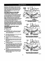
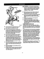
SQUARING THE MITER TABLE
TO THE FENCE
See Figures 13- 16.
• Unplugyoursaw.
,_ WARNING: Failureto unplugyoursaw could
resultin accidentalstartingcausing possible
sadous personalinjury.
• Push downon thesaw arm and pulloutthe look
pinto release thesaw arm.
• Raise saw armto itsfull raised position.
• Loosenthe miter lockhandle approximatelyone-
half tum.
• Depressthemiter lockplate and rotatethe miter
table untilthe pointer on the control arm isposi-
tioned at 0°.
• Release the miterlockplate and securelytighten
the miter lockhandle.
• Laya framingsquarefiat on the mitertable. Place
one leg ofthe square againstthe fence. Placethe
otherleg ofthe square besidethe zero clearance
throatplate inthe miter table. The edge of the
squareand the zero clearance throatplate in
the mitertable shouldbe parallelas shownin
figure 13.
• If the edge ofthe framing square and the zero
clearancethroatplate inthe mitertable are not
parallelas showninfigures 14 and 15, adjust-
mentsare n_:led.
..c,//
SQUARE I _ _ MITERTABLE
LOCKHANDLE
VIEWOFMITERTABLESQUAREWITHFENCE
ANDCORRECTLYADJUSTED
Fig. 13
FRAMINa _ _' ZEROCLEARARCE
SQUARE % )' THROATPLATE
VIEWOFMITERTABLENOTSQUAREWITH
FENCE,ADJUSTMENTSAREREQUIRED
Fig. 14
FENCE
MITERTABLE
FRAMING ZEROCLEARANCE
SQUARE THROATPLATE
VIEWOFMITERTABLENOTSQUAREWiTH
FENCE,ADJUSTMENTSAREREQUIRED
Fig. 15
15

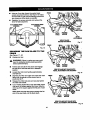
• Usingan6mmkey,loosenthesockethead
screwssecuringthefence.See Figure 16.Adjust
thefence leftor rightuntiltheframingsquare and
zero clearancethroat plataare parallel.
• Retightenthe screws securelyand recheckthe
fence-to-tablealignment.
6 mmSOCKETHEAD
SCREW(S)
6 mmSOCKETHEAD
SCREW(S)
Fig. 16
SQUARING THE SAW BLADE TO THE
FENCE
See Figures 17- 20.
• Unplugyoursaw.
_l, WARNING: Failuretounplugyoursaw could
resultin accidental startingcausingpossible
sedouspersonalinjury.
Pullthe saw arm all the way downand engage
the lockpinto holdthe saw arm in transport
position.
Loosen the miter lock handle approximately
one-half turn.
Depress the miter lock prate and rotate the miter
table untilthe pointer on-the controlarm is
positionedat 0°.
Release the miter lockplate and securelytighten
the miterlock handle.
Lay a framing square flaton the mitertable. Place
one legof the squareagainstthe fence. Slide the
other legof the square againstthe fiatpart of saw
blade.
Note: Make sure thatthe square contactsthe flat
partof the saw blade, notthe bladeteeth.
FENCE
FENCE
FENCE
MITER FRAMING
TABLE SQUARE
VIEWOFBLADE
SQUAREWITHFENCE
MITER
LOCKHANDLE
Fig. 17
MITER FRAMING
TABLE SQUARE
VIEWOFBLADENOTSQUAREWITH
FENCE,ADJUSTMENTSAREREQUIRED
Fig, 18
BLADE
MITER FRAMING
TABLE SQUARE
VIEWOFBLADENOTSQUAREWITH
FENCE,ADJUSTMENTSAREREQUIRED
Fig. 19
16

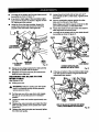
• Theedgeofthesquareandthesawbladeshould
beparallelasshowninfigure17.
• If the frontor beck edge of thesaw bladeangles
away fromthe square as showninfigures 18 and
19, adjustmentsare needed.
• Usingthe 8 mm hex key provided,loosenthe
sockethead screws thatsecure the mounting
brackettothe mitertable. See Figure20.
8 mmSOCKET
MITER
TABLE
MOUNTING
8 mmHEXKEY BRACKET
WRENCH Fig.20
• Rotate the mountingbracket leftor rightuntilthe
saw blade is parallelwiththe square.
• Retightenthe screws securelyand recheckthe
blade-to-fencealignment,
SQUARING THE BLADE TO THE
MITER TABLE
See Rgures 21-24.
• Unplugyoursaw.
_lb WARNING: Failureto unplugyoursaw could
resultin accidental startingcausingpossible
sadous personalinjury.
• Pullthe saw arm all the way downand engage
the lock pinto holdthe saw arm intransport
position.
• Loosenthe miterlock handle approximatelyone-
half tum.
• Depressthe miter lockplate and rotatethe miter
table untilthe pointer on the controlarm isposi-
tioned at 0°,
• _ Release the miter lockplate and securelytighten
the miter lock handle.
Loosen bevel lockknoband set saw arm at 0"
bevel (blade set90" to miter table). Tightenbevel
lockknob.
Place a combinationsquare againstthe miter
table and the fiatpart ofsaw blade,
Note: Make sure thatthe square contactsthe flat
part ofthe saw blade, notthe bladeteeth.
Rotate the bladeby handand checkthe blade-to-
table alignmentat severalpoints.
The edge of the square andthe saw bladeshould
be parallelas shownInfigure21.
FENCE
MITER
TABLE
COMBINATION
SQUARE
MITER
LOCKHANDLE
CORRECT_EWOFBLADE
SQUAREWITHMITERTABLE
Fig. 21
• Ifthe top or bottomofthe saw bladeangles away
from the square as showninfigures22 and 23,
adjustmentsare needed.
FENCE
COMBINATION
SQUARE
TABLE
VIEWOFBLADENOTSQUAREW111tMITER
TABLE,ADJUSTMENTSAREREQUIRED
Rg. 22
17

FENCE PIVOT ADJUSTMENTS
COMBINATION
MITER SQUARE
TABLE
VIEWOFBLADENOTSQUAREWITHMITER
TABLE,ADJUSTMENTSAREREQUIRED
Fig.23
• Usinga 10 mm wrenchor adjustablewrench,
loosen the lock nut secudngpositivestopadjust-
ment screw.Also loosenbevel lockknob.
• Adjustpositivestopadjustmentscrewto bdng
sew bladeintoalignmentwiththe square. See
F/gum 24.
POSITIVESTOP
ADJUSTMENT
45°ANGLES
Fig.24
• Retightenbevel lock knob. Next, retightenlocknut
securingthe positivestop adjustmentscrew.
Recheck blede-to-table alignment.
Note: The above procedurecan be usedto check
blade squarenessof the saw bladeto the rarer
table at both0° and 45° angles.
Your sew hasthree scale indicators,twoon either
side of the bevel scale and one onthe miterscale.
After squaringadjustmentshave been made, it may
be necessaryto loosen the indicatorsscrewsand
resetthem tozero.
Note: These adjustmentswere made at the factory
and normallydo not requirereadjustment.
TRAVEL PIVOT ADJUSTMENT
• The saw arm shouldrisecompletelyto the up
positionby itself.
• If the sew armdoes notraise byitselfor ifthere is
play in the pivotjoints,have saw repairedbya
qualifiedservice technicianat yournearest Sears
store toavoid riskof personalinjury.
BEVEL PIVOT ADJUSTMENT
• Your compoundmiter saw shouldbevel easilyby
looseningthe bevel lock knoband tiltingthe sew
armto the left.
If movement istightor ifthere is playin the pivot,
have saw repairedby a qualifiedservicetechni-
cian at yournearest Sears store to avoiddskof
personal injury.
DEPTH STOP
I
The depth stop limitsthe blade'sdownwardtravel. It,
allowsthe bladeto go belowthe mitertable enoughto
maintainfull cuttingcapacities. The depthstop posi-
tionsthe blade 114in. from the mitertable support.
Note: The miter table supportis locatedinsidemiter
table.
The depthstopis factory setto providemaximum
cuttingcapacity for the 10 in. sew blade providedwith
yoursaw. Therefore, the saw blade providedshould
never need adjustments.
However, when the diameterofthe bladehas been
reduced due to sharpening, it may be necasseryto
adjustthe depth stop toprovidemaximumcutting
capacity. Also, when a new bladeis installed,it is
necessary tocheck the clearanceofthe bladetothe
miter table supportbeforestartingthe saw. Make
adjustmentsif needed.
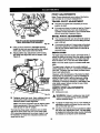
DEPTH STOP ADJUSTMENTS
See Figure25.
• Unplug yoursaw.
_k WARNING: Failureto unplugyoursaw could
resultin accidentalstartingcausing posaible
serious personalinjury.
To adjust thedepth stopuse a 17 mmwrenchor
adjustablewrenchand loosenthe hex nutat the
rear ofthe mitersew arm.
Use the 5 mm hax key wrench providedtoadjust
the depth stop adjustmentscrew. The saw blade
islowered bytuming the screw counter-cloctoNIse
and raised byturningthescrewclockwise.
18

DEPTHSTOP L...
SCREW
BEVEL
MITER
TABLE
POSITIVE LOCKNUT(S)
STOPADJUSTMENT
SCREWFOR0°ANGLES Fig,25
Lowertheblade intothe zero clearancethroat
plate ofthe mitertable. Check bladeclearance
and maximumcuttingdistance(distancefrom
fencewhere bladeenters) to frontofmitertable
slot.
• Readjustifnecessary.
_k WARNING: Do not startyourcompound miter
sew withoutcheckingfor interferencebetween
the bladeand the mitertable support.Damage
couldresultto the blade ifit strikesthe miter
table supportduringoperationofthe saw.
• Tightenthe hex nutwith a 17 mm wrenchor
adjustablewrench.
• To preventthe depth stop adjustmentscrewfrom
tumingwhiletightening_thehexnut,carefullyhold
itwiththe hex key wrenchwhiletighteningthe
hsx nut.
APPLICATIONS
(Use only for the purposes nsted below)
• Crosscuttingwood and plastic.
• Crosscuffingmiters,joints,etc. for pictureframes,
moldings,doorcasings, and fine joinery.
Note: The 104 toothcrosscutblade providedisfine
for mostwoodcuttingoperations,but for fine joinery
cutsor cuffingplastic,use one of theaccessory
bladesavailable from your nearest Sears store.
WARNING: Beforestartingany cutting
operation,clamp or boltyourcompoundmiter
saw to a workbench. Never operateyourmiter
sew on the flooror in a crouchedposition.
Failureto heed this warningcan resultin serious
personalinjury.
CUTTING WITH YOUR COMPOUND
MITER SAW
_, WARNING: When usinga work clamp or
C-clamp tosecure yourworkpieca,clamp
workpieceon one side ofthe bladeonly.The
workpiscemust remainfree on one side ofthe
blade to preventthe bladefrombindingin
workplece. The workpiecebindingthe bladewill
cause motorstallingand kickback.This situation
could cause an accidentresultingin possible
sedous personalInjury.
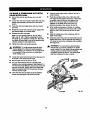
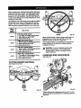
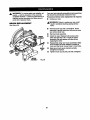
CROSSCUTTING
See Figure26.
A crosscutismade bycuttingacrossthe grain ofthe
workplace.A straightcrosscutis madewith the miter
table set at the zero degree position. Mitercrosscuts
are made withthe mitertable set at some angleother
then zero.
TO CROSSCUT WITH YOUR MITER
SAW:
• Pullout the lockpin and liftsew arm toitsfull
height.
• Loosenthe miterlockhandle. Rotate the miter
lock handle approximatelyone-half tum tothe left
to loosen.
• Pressthe miter lockplate downwith yourthumb
and hold.
• Rotate the controlarm untilthe pointer alignswith
the desiredangle on the miterscale,
• Release the miter lockplate.
Note: You can quicklylocate 0°, 22-1/2° leftor
dght, and 45' left or rightby releasingthe lock
plate as you rotatethe control arm. The lock plate
willseat itselfin one ofthe positivestop notches,
locatedinthe mitertable frame.
• Tighten the miter lock handlesecurely.
WARNING: To avoidsedous personalinjury,
always tightenthe miterlock handle securely
before makinga cut. Failuretodo so couldresult
in movementofthe controlarm or mitertable
while makinga cut.
19

• Slowlylowerthe bladeintoand throughthe
workpiece.See Figure26.
• Release the switchtdgger and allowthe saw
STRAIGHT blade tostop rotatingbeforeraisingthe blade out
CROSSCUT of workpiece.Wait untilthe eisctdcbrake stops
blade fromtuming before removingthe workpiece
from the mitertable.
BEVEL CUT
See Figures27 and 28.
A bevel cut ismade bycuttingacrossthe grainof the
workplacewiththe bladeangled tothe workplace.A
straightbevel cutis made withthe mitertable set at
the zero degree positionand the blade set at an angle
between 0"and 45°.
LEFTSiDE
LEFT
iNDICATOR
POINT
RIGHTSIDE
RIGHT
INDICATOR
POINT
C-CLAMP Rg. 26
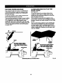
• Placethe workplacefiat on the mitertable with
one edge securelyagainstthe fence. Ifthe board
iswarped, placethe convex side againstthe
fence, if the concave edge of a boardis placed
againstthe fence, the boardcould collapse on the
blade at the end of thecut, jamming theblade.
See Figures33 and 34.
• When cuttinglongpieces of lumberor molding,
supportthe oppositeend ofthe stock witha roller
stand or witha work surface levelwith thesaw
table.
• Aligncuttinglineon the workpiecawiththe edge
ofsaw blade.
Grasp the stockfirmlywithone handdndsecure
itagainstthe fence. Usa the optionalworkclamp
or a C-clampto secure theworkpiecawhen
possible.See Figure26.
_1= WARNING: To avoidsadous personalinjury,
keepyour handsoutsidethe no handszone; at
least3 in. fromblade. Never performany cutting
operationfreehand (withoutholdingworkplace
againstthe fence). The blade couldgrabthe
workpleceif itslipsor twists.
• Beforetumingon the saw, performa dry runofthe
cuttingoperationjustto make sure that no
problemswilloccurwhen the cut ismade.
• Grasp the saw handlefirmly,prass the lock-offtab
down,then squeeze the switchtrigger:Allow
several secondsfor the bladeto reach maximum
speed.
SCALE
SCALE
MOUNTINGBRACKET Fig. 27
TO BEVEL OUT WITH YOUR MITER
SAW:
• Pullout the lockpin and liftsaw arm to its full
height.
• Loosen the miterlock handle.Rotate the miter
lock handle approximatelyone-haftturntothe left
to loosen.
Pressthe miter lockplate downwithyourthumb
and hold.
Rotate the controlarm untilthe pointer aligns with
zero on the miterscale.
Release the miter lockplate.
Note: You can quicklylocate zero by releasing
the lock plateas you rotatethe control arm. The
lock plate willseat itselfin one ofthe built-in
positivestop notches,locatedin the miter table
frame.
• Tightenthe miter lockhandle securely.
_IL WARNING: To avoid sedouspersonalinjury,
alwaystightenthe miter lockhandle securely
before makinga cut. Failureto do so couldresult
in movement ofthe controlarmor mitertable
while makinga cut.
2O
Page is loading ...
Page is loading ...
Page is loading ...
Page is loading ...
Page is loading ...
Page is loading ...
Page is loading ...
Page is loading ...
Page is loading ...
Page is loading ...
Page is loading ...
Page is loading ...
Page is loading ...
Page is loading ...
Page is loading ...
Page is loading ...
Page is loading ...
Page is loading ...
-
 1
1
-
 2
2
-
 3
3
-
 4
4
-
 5
5
-
 6
6
-
 7
7
-
 8
8
-
 9
9
-
 10
10
-
 11
11
-
 12
12
-
 13
13
-
 14
14
-
 15
15
-
 16
16
-
 17
17
-
 18
18
-
 19
19
-
 20
20
-
 21
21
-
 22
22
-
 23
23
-
 24
24
-
 25
25
-
 26
26
-
 27
27
-
 28
28
-
 29
29
-
 30
30
-
 31
31
-
 32
32
-
 33
33
-
 34
34
-
 35
35
-
 36
36
-
 37
37
-
 38
38


Craftsman 10 IN. COMPOUND MITER SAW 315.23538 User manual
- Category
- Power tools
- Type
- User manual
- This manual is also suitable for
Ask a question and I''ll find the answer in the document
Finding information in a document is now easier with AI
Related papers
-
Craftsman 315.21211 User manual
-
-
-
-
-
-
-
-
-
