F2412MVD8SS
8 Series 1.2 CU. FT. Microwave Drawer
Spec sheets are subject to change without notice.
For further questions and more detailed information, please
visit forteappliances.com.
1870 Bath Avenue, Suite 3, Brooklyn, NY 11214
DIMENSIONS AND INSTALLATION INFORMATION
MICROWAVE DRAWER MEASUREMENTS
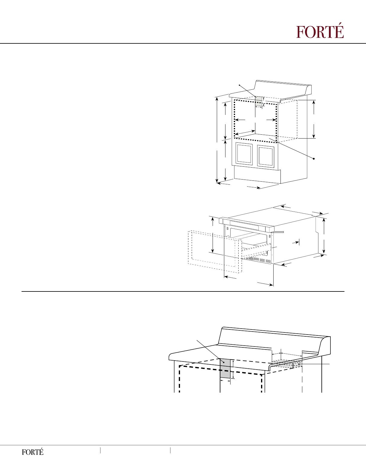
Figures 1 & 2 contain many Microwave Drawer measurements
for reference when planning the drawer’s location. This
Microwave Drawer can be installed below any electric or gas
wall oven.
Note: Can also be installed using an electric outlet in an
adjacent cabinet within the area where the provided
electrical cord can reach. Power cord access hole in abinet
should be a minimum 1 1/2: diameter hole and debarred of
all sharp edges.
Important: Always all sufcient power cord length to the
electrical outlet to prevent tension, and always check
electrical codes for requirements.
ELECTRICAL OUTLET AND ANTI-TOP BLOCK
To reduce the risk of tipping the microwave drawer, the anti-top
block must be properly located 14
13/16”
above the oor where
the microwave will sit. The 6” anti-top block must be provided
by the installer. The anti-tip block prevents serious injury which
might be result from spilled hot liquids. If the microwave drawer
is ever moved to a different location, the anti-top block must
also be moved and installed. When secured to the wall,
make sure the screws completely penetrate the dry wall and
are secured in wood or metal to stabilize the block. When
fastening, be sure the screws do no penetrate electrical wiring
or plumbing. The electrical requirements are 120 volt, 60 Hz, AC
only, and 15 amp. It is recommended that a separate circuit
serving only this appliance is provided. The drawer is equipped
with a 3-prong grounding plug and must be plugged into a
wall receptacle that is properly installed and grounded. If you
only have a 2-prong outlet, allow a qualied electrician to
install a correct wall receptacle.
NOTE: If you have any questions about the grounding or
electrical instructions, consult a qualied electrician or service
person. The microwave drawer can also be installed using an
electrical outlet in an adjacent cabinet within the area where
the provided electrical cord can reach. Always check if the
electrical cord can reach.
GROUNDING INSTRUCTIONS
This appliance must be grounded. The microwave drawer must be plugged into a wall
receptacle that is properly installed and grounded in accordance with the National
Electrical Code along with local codes and ordinances. In the event of an electrical short
circuit, grounding reduced risk of electrical shock by providing an escape wire for the
electrical current.
CLEARANCES AND DIMENSIONS
• Dimensions that are shown in Figure 1 must be used. Given
dimensions provide minimum clearance. Locate outlet in the
shaded area in the upper left-hand corner of the cutout.
(See Figure 3)
• Contact surface must be solid and level. Pay special attention
to the oor on which the Microwave Drawer will sit. The oor of
the opening should be constructed of plywood strong enough
to support the weight of the oven (about 100 pounds).
• Check location where the Microwave Drawer will be installed
for proper electrical supply.
• Your oven can be built into a cabinet or wall by itself, or
under a gas or electric wall oven.
• Be sure that the clearance of the oor between the wall
oven and the microwave drawer is a minimum of 2 inches.
• The microwave interior will easily accommodate a 9” x 13”
oblong dish or a bag of microwave popcorn.
36”/91.44 CM
COUNTERTOP
HEIGHT
14
13/16”
37.62 CM
OPENING
14
13/16
”
37.62 CM
BOTTOM OF
ANTI-TIP BLOCK
SHELF MUST
SUPPORT
100 LBS (45 KG)
SUGGESTED
ELECTRICAL OUTLET
LOCATION
22
2/16”
/56.20 CM
OPENING
4”
5”
23
8/16”
/56.69 CM
OPENING
19”
48.26 CM
OPENING
24”/60.96 CM
OPENING
14.
15/16”
38 CM
1
11/16”
/4.29 CM
DOOR THICKNESS
14
15/16”
38 CM
23
10/16”
/60 CM
15”/38.10 CM
DRAWER
OPENING
23
5/16”
/59.18 CM
21
9/16”
/54.77 CM
FIGURE 1
FIGURE 2
FIGURE 3
ANTI-TIP
BLOCK
SUGGESTED ELECTRICAL
OUTLET LOCATION
4”
5”
6”
3
8/16”
