Risco lightsys 2 User manual

Category
Security access control systems
Type
User manual
LightSYS2
User Manual
Page 2
.
Register with RISCO Cloud (if enabled)
Registering with RISCO Cloud enables you to monitor and control your LightSYS™2 system.
Note: Registration and connection of your system to www.riscocloud.com may depend on your
installer.
1. Go to www.riscocloud.com/register.
2. Enter your first name and last name.
3. Enter your email address as Login Name (required for 1st time activation).
4. Define password (minimum of 6 characters and at least one digit) and confirm.
5. Enter in the 15 digits Panel ID as it appears: on the postcard that arrived with
the panel or supplied by the installer (also available in the keypad menu as
described below)
6. Complete registration form and click Register.
7. To complete registration open the email message received on the email account
you defined as Login Name.
Login to RISCO Cloud
1. Go to www.riscocloud.com.
2. Enter User Name and Password (same as supplied during the registration
process).
3. Enter Passcode/PIN (LightSYS™2 User Code).
4. Click Enter.
iRISCO – RISCO’s Smartphone Application
Homeowners can now enjoy the iRISCO Smartphone app for smart and easy control of
their LightSYS™2 system from any location.
Download the iRISCO app from the Apple App store or Android Play Store (Search for
“iRISCO”).
Locating Panel ID in Keypad
1. From the main display press .
2. Enter master code (default code 1234) followed by .
3. Scroll to the option “View” and press .
4. Scroll to “Service Info” and press
Page 3
5. Scroll to “Panel ID” and press . 15 digit Panel ID is now displayed.
Interface:
LCD Keypad (432KP)
Full (Away) Arm
Code >
Part (Stay) Arm
Code >
System Disarm and
Silence an Alarm
Code>
Partition Away Arm
Code > > Partition No. >
Partition Stay Arm
Code >
> Partition No. >
Partition Disarm Code> > Partition No. >
Duress Unset
Duress Code >
Panic Alarm
Pressing
simultaneously for 2 seconds
Fire Alarm
Pressing simultaneously for 2 seconds
Medical Alarm
Pressing simultaneously for 2 seconds
Quick Zones Bypass
Code > [Zone No.]
Activate Output
[Code] [Activities] [Util Output Num]
Define Follow-Me
>[Code] [Follow Me] [Define]
View Trouble
[Code] [View] [Trouble]
View Event Log
[Code] [Event Log]
Keypad Chime On/Off
[Code] [Activities] [Keypad sound] [Chime]
Edit User Code
[Code] [Codes/Tags] [Define]
Page 4
Press for 2 seconds to view 2 to view
followed by code
LED display of system status (see
LED display of system
Indicators below) status (see Indicators below)
Output Control
Press 1/2/3 for 2 seconds
followed by code
2
Wake up keypad Press
Status Request
Press
for 2 seconds
Page 5
2-way Remote Control keyfob
Notes:
1. Consult your
installer for the operations defined with a code.
2. The proximity tag can be used instead of code.
Operation
Quick
High Security Mode
1
Full Arm
> [Code]
Partial
Arm*
> [Code]
Full
Disarm
[Code >
]
System
Status
for 2 seconds
for 2 seconds >
Code
Output Control A/B/C
for 2
seconds
for 2
seconds > [Code]
Panic Alarm
simultaneously for 2 seconds
Clear Operation
*For Part setting with no entry delay, press and hold
for two seconds
Page 6
Page 7
SETTINGS sub-tab
System user and codes Edit, Delete and ADD NEW USERs
Web interface users and codes EDIT user fields and access credentials
Change Password Enter Old/New/Confirm > SET NEW PASSWORD
Quick Zone Bypass Select ZONE xx > Omit > Update
Change Appearance Select Color Scheme
Alerts/Add New Contact Enter Name, Email/Mobile phone #.
Select Alert Language, Partition association
,
and toggle Set/Unset Email and SMS
Time Zone Select system time zone
HISTORY sub-tab
Review activity log and export
AUTOMATION sub-tab
SMS
For a full list of SMS operations, refer to
Appendix D
SMS
Operation.
Page 8
Utility
Outputs
Toggle
ON/OFF >
Update
1-way Remote Control keyfob
Full Arm Press
Disarm Press the button. All partitions
assigned to the button will be disarmed
Stay Arm Press button or button 4 (if defined)
Partition Arm Press button or button 4 (if defined)
Full Arm [Code][A], example, 1234A
Full Disarm [Code][D], example, 1234D
Stay Arm [Code][H], example, 1234H
Partition Arm [Code][A] [Partition No.] examples:
To arm partitions 1: 1234A1
To arm partitions 1 and 2: 1234A12
Partition Disarm [Code][D] [Partition No.] Example 1234D1
Page 9
is in Exit Delay
Slow Flash: Ready to arm with
open Exit/Entry zone
( Stay / Bypass): On: System armed at Stay /
Bypass zones in the system
Off: No bypass zones
(Fire):
On: Fire alarm
Off: No fire alarm
(Ready):
On
Ready to arm :
Off
:
Not ready to arm
Rapid Flash
:
Alarm
(Tamper) :
On
Tamper alarm :
Off
No tamper alarm
:
)
(
Proximity
[
Touchscreen only]
Flashing: Indicates keypad has a
proximity reader
2-
way Slim Keypad
LED Indicator
State
Status
Color
Blue Blink
During communication with the panel
Red On
Slow flash
Rapid flash
System fully or partially armed
During exit delay
During alarm
Blink Green Trouble indication in the system
while the system is unset*
Green/Red
Waiting for code to be entered Toggle
2-
way Keyfob
Indicators:
LCD and Touchscreen Keypads
(Power):
On
:
Power OK, No troubles
Off
:
No power
Rapid Flash
:
System trouble
(Arm) / RED LED
On
:
System armed
(
Away or Stay)
Off
:
System
disarmed
Slow Flash: System
Page 10
Flash: Fire trouble
Operation
LED* (Send command)
LED* (Receive Status)
Full Setting (Away) Green Red
Part Set (Stay Arm) Green Orange
Unset (Disarm) Green Green
Alarm Green Flash LED
* If the LED changes to orange, it indicates a low battery condition.
Table of Contents
Chapter 1 Mastering Your System ......................................................................... 12
Introduction ........................................................................................................................................ 12
Main System Capabilities ................................................................................................................. 12
LightSYS™2 Architecture ................................................................................................................ 13
User Operating Tools ....................................................................................................................... 13
System Monitoring ............................................................................................................................ 15
System Tones .................................................................................................................................... 17
Chapter 2 Arming and Disarming .......................................................................... 19
Arming your system .......................................................................................................................... 19
Disarming your system ..................................................................................................................... 23
Additional Arm/Disarm Capabilities ................................................................................................ 27
Emergency Alarms ............................................................................................................................ 28
Chapter 3 User Functions and Settings ................................................................ 29
User Codes ........................................................................................................................................ 29
Proximity Tags ................................................................................................................................... 32
Setting and Changing System Time and Date .............................................................................. 34
Setting Follow Me Destinations ....................................................................................................... 34
Bypassing zones ............................................................................................................................... 35
Scheduling Weekly Programs ......................................................................................................... 36
Macro Keys ........................................................................................................................................ 38
Parking Control with LightSYS™2 Gate Control Keyfobs ............................................................ 40
Complete List of User Functions ..................................................................................................... 42
Appendix A – System Troubles ............................................................................. 49
Appendix B – Glossary ........................................................................................... 50
Appendix C – Scheduling Tables ........................................................................... 52
Page 11
Appendix D – SMS Operation................................................................................. 53
Appendix E – System Testing and Maintenance .................................................. 55
Mastering Your System
Page 12
Chapter 1 Mastering Your System
Introduction
Congratulations on your purchase of RISCO Group's LightSYS™2 Security System. The
LightSYS™2 has been specifically designed to meet a wide range of security needs for
residential and commercial applications.
LightSYS™2 is designed to recognize abnormal conditions and inform the system of the
status of any protected door, window, hallway, room, or area. It supports the capabilities of
communicating with a Central Monitoring Station or to your mobile phone using friendly
and easy to understand verbal messages as well as SMS, E-mail messages or cloud channel
reporting.
The LightSYS™2 contains a variety of programming features including smartphone apps
and web control. Ask your installer which features have been programmed for your
system.
This manual describes how to operate your system. It will guide you through
programming instructions for main system features as well as basic arming and disarming
commands for the system
Main System Capabilities
Up to 32 sensor devices
16 User codes + Grand Master code
4 authority levels for different system users
Optional user proximity tag to be used
instead of a code
Up to 4 partitions
4 wired / wireless keypads
Up to 4 sirens
Up to 16 full control remote controls
Up to 200 gate control remote controls
500 Events Log
16 Follow Me destinations
Up to 14 outputs
X-10 support for home automation
4 automatic scheduling programs
Smartphone operation of principal
functions
Mastering Your System
Page 13
LightSYS™2 Architecture
Your LightSYS™2 controls and monitors a variety of sensors, detectors, and contacts
placed throughout the premises, which provide external, perimeter and internal
burglary protection. The system is supervised, meaning that the panel checks the
status of each sensor to detect problems. If trouble is detected, you are notified both
with panel beeps and indicator lights as well as remote messaging.
The following diagram shows the components that make up the system:
User Operating Tools
LightSYS™2 can easily be managed locally or remotely depending on your system
configuration.
You can issue commands to the system and in turn, the system will communicate
information to you via its display, indicators, voice messages, SMS messages, Email
messages and by the sounds it makes.
Depending on your purchased supplementary modules, you can operate your system via
the following:
Mastering Your System
Page 14
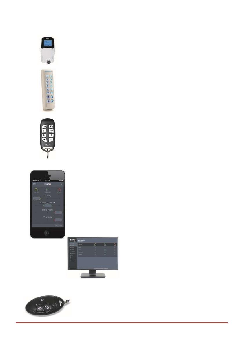
LightSYS™2 Keypad and proximity tag:
Locally through its LCD keypad(s), you can issue commands to your
system. In turn, the system can communicate
information to you through its display, indicators and by
the sounds it makes.
2-Way Slim Keypad
With support for up to three bi-directional wireless communication, 2-
Way slim keypads, LightSYS™2 now offers an outdoor-certified
tamper-proof power-saving option. The slim keypad offers the entire
range of arming and disarming as well as alarming options
2-Way 8 Button Remote Control:
Using the bi-directional 8 button remote control you can arm, disarm,
send a panic alarm, activate outputs and more. Being bi-directional the
remote control receives a reply status indication, via its 3 colored LEDs
and internal buzzer siren, from the panel for each command that it has
sent to the panel. For higher security, commands can be defined to be
activated with a 4 digit PIN code.
Smartphone Operations:
Homeowners can now enjoy the iRISCO Smartphone App for smart
and easy control of their LightSYS™2 system. The app enables users
to arm/disarm the system on-the-go, activate home automation
devices, bypass detectors, view the system’s status and history, and
much more. Available for iPhone, iPad and Android.
Note: Registration and connection of your system to
www.riscocloud.com may depend on your installer
Web Application:
RISCO Group’s interactive web application enables you to
monitor, control and configure your LightSYS™2 system
from any location. As with the Smartphone app, the
application is powered by the RISCO Cloud server.
Note: Registration and connection of
your system to www.riscocloud.com may depend on your
installer
4 Button Keyfob:
Using the wireless 4 button keyfob you can arm, disarm, send a
panic alarm and activate outputs.
Mastering Your System
Page 15
Remote Phone Operation:
If your system includes the voice module, it can provide audible information about
system status, and enable any remote, touch-tone (DTMF) telephone
to act as a keypad for the system. Upon event occurrence, such as
alarm activation, the voice module informs you by calling you and
playing a
prerecorded event announcement, as described in the 5IN1545 LightSYS Voice
Module Programming and Operations Guide.
SMS:
If your system is equipped with RISCO Group's GSM/GPRS
module it can provide information about the system by SMS
and enable operation of the system using SMS commands for
arming the system, disarming the system and more.
Configuration Software:
RISCO Group's Configuration Software enables the installer to
program the system and manage the system locally or remotely.
System Monitoring
Report to Monitoring Station
When a system event occurs, the control system sends a message to your monitoring
service describing the exact nature of the event. This enables the monitoring service to
perform the required action. Monitoring service notification can be implemented through
either regular telephone cellular communication or IP network.
A sensor detects The control system is alerted  An alarm is generated and
the monitoring service is notified
Mastering Your System
Page 16
Caution:
Remember that no security system can prevent emergencies. This system is only intended to
alert you in case of an emergency and should not take the place of prudent security
practices or life and property insurance.
Follow Me Messaging
When an alarm or event, the system can initiate a report message of up to 16 predefined
designated destinations using a voice announcement, SMS, smartphone app, or email to
express the active event.
SMS Example: Email Message Example:
Security System: Subject: Alarm Security Message: Intruder Alarm
21/01/2011 System Name: John's Residence
Intruder Alarm Event: Fire Alarm, Zone 5, Entrance door
Partition 1 Time: 01 April 2011; 16:12
Entrance Partition: Partition 1, First floor
Service Contact: Monitoring Station 01, 035676778
Your installer defines the type of reporting to a Follow Me destination. Consult your
installer for the report type for each destination.
The definition of the telephone number or Email address for each destination is defined by
the grand master (see page 33).
Notes:
Voice messaging requires using the LightSYS™2 voice module. This module also
enables the LightSYS™2 to announce various local messages to residents.
SMS messaging requires the use of the LightSYS™2 GSM/GPRS module.
Email messaging requires the use of the LightSYS™2 IP module.
LCD Status Display
The LCD status display will vary depending on the number of partitions in your system.
If your system is defined with only one partition, the LCD displays the partition name,
time and date.
If your system has two or three partitions, the LCD displays the system name, date, time
and the status of each partition. A status letter represents the partition’s status, as follows:
A: Partition Armed N: Partition Not Ready L
: Partition in Alarm
Mastering Your System
Page 17
S: Partition Stay Armed R: Partition Ready
LCD Blank Display
If defined by your installer, two minutes after the last keypad operation the keypad will be
disabled and the following display will appear on the LCD: Enter code:
To release the keypad and return to normal operation mode press: [CODE] + .
Note:
During blank display mode the Ready LED indicates a trouble in the system.
System Tones
In addition to the visual indications provided by your keypad(s), your system is designed
to produce audible annunciation after certain events. Depending on the circumstance, such
sounds may be made by your system's keypad(s) or sounders (for example, a siren or bell).
Note:
If defined by your installer, internal bell annunciation can be generated to
accompany any of the keypad sounds.
Event
Keypad Sound
Internal Bell
External Siren
Intrusion Alarm
Rapid beeping Rapid beeping Rapid beeping
Fire Alarm Rapid beeping Rapid beeping YES (staggered)
Keypad Police
Emergency
No sound (1) No sound (1) No Sound (1)
Keypad
Emergency /
Medical
A momentary chirp No sound No sound
Arming or
Disarming
No Sound System is armed:
1 chirp
System is disarmed:
2 chirps (Keyfob)
Disarm after alarm:
4 chirps (Keyfob)
System is armed:
1 chirp
Confirm
Operation
A one
-
second tone, if
completed correctly
No sound No sound
Mastering Your System
Page 18
Reject Operation
Three rapid error beeps,
if incorrect (2,3)
No sound No sound
Entry Delay
Countdown
Slowly repeating tones
until the entry delay time
period expires (2)
No sound No sound
Exit Delay
Countdown
Slowly repeating tones
until the exit delay time
period expires (2)
No sound No sound
Chime Sound
2 second buzzer beep (4)
No sound No sound
Notes:
1. Based on decisions made at the time your alarm system installation, keypads
may beep during this type of alarm.
2. Keypad beeps may be disabled at the user's discretion, see Buzzer On/Off,
page 41.
3. Press for two seconds to stop the fault beeps
4. Any intrusion zone, if selected for the chime feature, will, when violated
during the disarm period, cause the keypad to annunciate the event. The
chime can also be disabled when not required.
Arming and Disarming
Page 19
Chapter 2 Arming and Disarming
The following chapter describes how to operate your LightSYS™2 locally from the LCD
keypad. For system operation from other accessories, refer to the instructions supplied
with the product.
As a user of your security system, you'll mostly be concerned with the keypad.
The LightSYS™2 LCD keypad is the primary system interface. Each keypad in your system
reports its status via its LCD icons, as described below. Through its keys, you can enter
commands to arm and disarm the system, bypass intrusion zones, report emergencies, and
more, as described in the subsequent chapters of this manual. For detailed information
regarding the keypad interface, refer to the instruction supplied with the keypad.
Notes:
1. There are two types of LCD keypads, with and without proximity for non-contact
arming and disarming.
2. Each keypad in the system is assigned to a particular partition, meaning that
commands entered in a keypad are implemented only in the partition to which it is
assigned. For example, pressing the Quick Arm key on a keypad assigned to
partition 1 arms only partition 1
Arming your system
Arming your system causes the intrusion detectors to trigger an alarm when violated. You
can arm your system by code arming, in which you need to use your user code, or you can
use quick arming (without using a code).
Note:
If during code setting you enter a wrong user code, the keypad produces
three short beeps. Simply re-enter the correct sequence.
Remember, fire protection and the protection offered by the keypad's emergency keys are
always armed and always available (if authorized by your installer).
Before arming the system:
1. Verify that the (ready) icon is lit or flashing indicating that system is READY to
be armed.
2. Make sure that the system includes no violated zones and is ready to be armed.
3. If the system is NOT ready to be armed, secure or bypass the violated zone(s) (see
page 34), and then proceed.
Notes:
Arming and Disarming
Page 20
If you are unable to arm the system, press to view system messages.
If defined by your installer, your system can be defined to accept force arming. This
definition arms the system regardless of open zones when using a keyswitch or
automatic arming. Note that force arming the system results in leaving partition(s)
unsecured.
If defined by your installer, it might be required that all troubles in the system
should be confirmed to enable the arming operation.
Your LightSYS™2 supports the following kinds of arming:
Away (Full) arming
Away arming ( ) prepares all of the system's intrusion detectors to activate an alarm if
violated, and is used when leaving the premises. Once you have armed the system, exit via
the designated final exit door.
To fully arm your system:
1. Verify that the system is ready to be armed.
2. Enter your user code followed by or hold the tag close to the keypad's keys.
3. Leave the premises and close the door. The keypad beeps and the icon flashes
while the system counts down the exit delay time period.
4. When the exit delay time period has expired, the icon lights steadily.
Note:
If defined by your installer, system sirens can sound one chirp, indicating that the system is
armed.
Stay (Home) arming
Stay arming ( ) activates only perimeter detectors (as defined by your installer), enabling
individuals to remain inside and move about the premises while the system is partially
armed.
To stay arm your system:
1. Verify that the system is ready to arm.
2. Enter your user code followed by .
3. During the exit delay time period:
the keypad beeps
the icon flashes
  • Page 1 1
  • Page 2 2
  • Page 3 3
  • Page 4 4
  • Page 5 5
  • Page 6 6
  • Page 7 7
  • Page 8 8
  • Page 9 9
  • Page 10 10
  • Page 11 11
  • Page 12 12
  • Page 13 13
  • Page 14 14
  • Page 15 15
  • Page 16 16
  • Page 17 17
  • Page 18 18
  • Page 19 19
  • Page 20 20
  • Page 21 21
  • Page 22 22
  • Page 23 23
  • Page 24 24
  • Page 25 25
  • Page 26 26
  • Page 27 27
  • Page 28 28
  • Page 29 29
  • Page 30 30
  • Page 31 31
  • Page 32 32
  • Page 33 33
  • Page 34 34
  • Page 35 35
  • Page 36 36
  • Page 37 37
  • Page 38 38
  • Page 39 39
  • Page 40 40
  • Page 41 41
  • Page 42 42
  • Page 43 43
  • Page 44 44
  • Page 45 45
  • Page 46 46
  • Page 47 47
  • Page 48 48
  • Page 49 49
  • Page 50 50
  • Page 51 51
  • Page 52 52
  • Page 53 53
  • Page 54 54
  • Page 55 55
  • Page 56 56
  • Page 57 57
  • Page 58 58
  • Page 59 59
  • Page 60 60
  • Page 61 61

Risco lightsys 2 User manual

Category
Security access control systems
Type
User manual

Ask a question and I''ll find the answer in the document

Finding information in a document is now easier with AI