4
• The unit should be located with consideration of
minimizing the length of the supply and return ducts. If
practical, place the air conditioner and its ducts in an
area where they will be shaded from the afternoon sun,
when the heat load is greatest.
• Thelength ofthesupplyand returnductsshouldbe
kept to a minimum with no sharp radius bends.
• Overhead obstructions, poorly ventilated areas, and
areas subject to accumulation of debris should be
avoided. The hot condenser air must be discharged
up and away from the home, and if possible, in a
direction with the prevailing wind. Do not place the unit
in a confined space. See
Figure 9, (page 14) for unit
dimensions.
• Sufcient clearance for unobstructed airow through
the outdoor coil must be maintained in order to achieve
rated performance.
• Consideration should also be given to availability of
electric power, service access, noise, and shade.
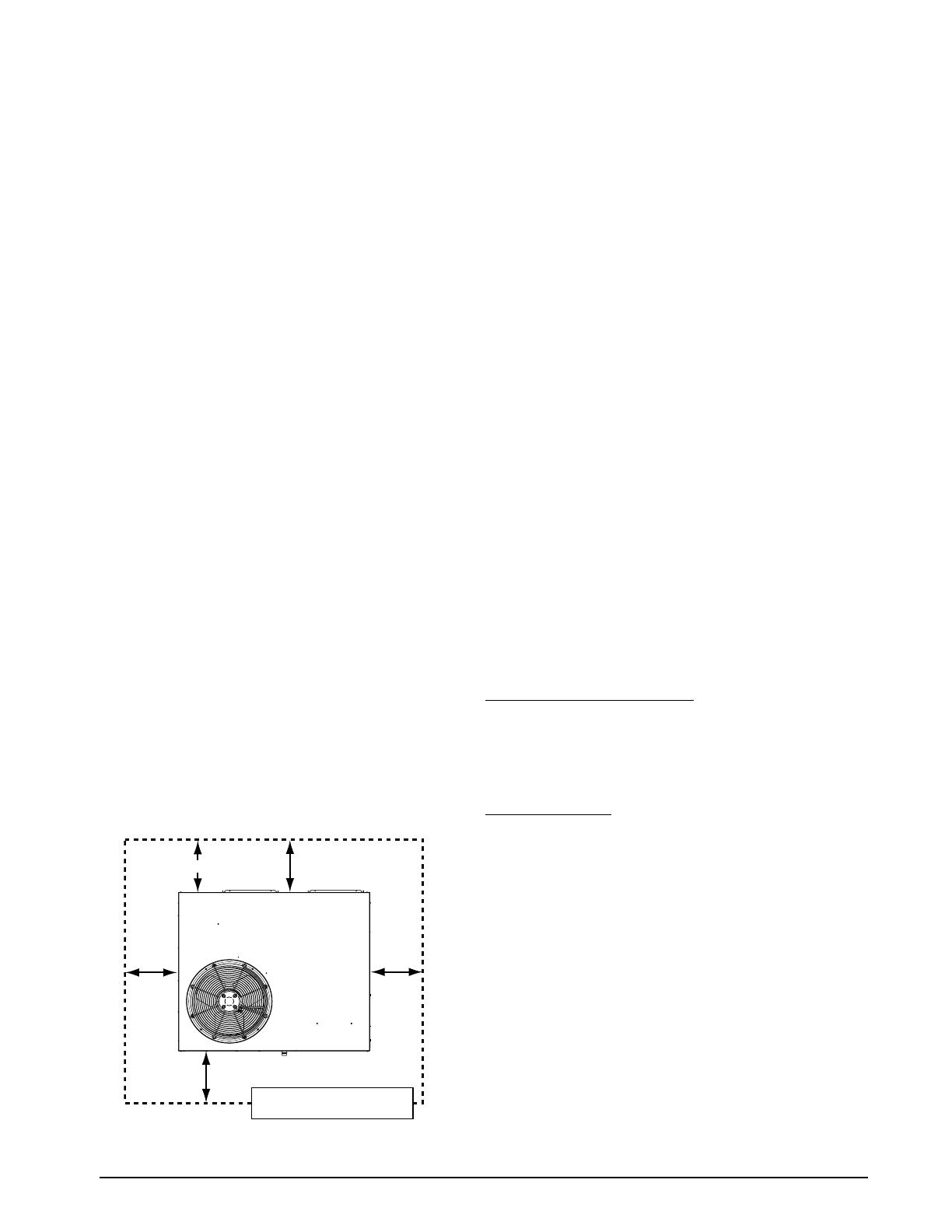
Minimum Clearance Requirements
P8SE units are certified as cooling equipment for outdoor
installation only. Figure 1 displays the minimum clearances
to obstructions for downflow and Horizontal discharge.
Units may be installed on Class A, B, or C roof covering
material when used with bottom supply and return air
ducts. If using bottom discharge with return air ducts, a
roof curb must be installed prior to unit installation. See
Rigging and Hoisting section for setting of the unit.
Sufficient clearance for unobstructed airflow through the
outdoor coil must be maintained in order to provide room
for proper servicing and achieve rated performance. See
Figure 1 for minimum clearances to obstructions.
Service Access Clearances
Blower access panel side .......................................... 36”
Electrical compartment access panel side ................ 36”
Clearance between overhang & top of unit ...............72”
Clearance around condenser coil area to wall or
shrubs (excludes duct panel side) .............................36”
Duct Clearances
Supply and return air ducts .........................................0”
Duct connection side ...................................................0”
Air Ducts
This unit is designed only for use with a supply and return
duct. Air ducts should be installed in accordance with the
standards of the National Fire Protection Association
Standard for Installation of Air Conditioning Systems
(NFPA 90A), Standard for Installation of Residence Type
Warm Air Heating and Air Conditioning Systems (NFPA
90B), and all applicable local codes. NFPA publications
are avaialable by writing to: National Fire Protection
Association, Batterymarch Park, Quincy, ME 02269 or
visit www.NFPA.org on the web.
• Designtheductworkaccordingtomethodsdescribed
by the Air Conditioning Contractors of America (ACCA).
• Theductsmustbeproperlysizedandnotexceed.2”
W.C. pressure drop at 400 scfm per nominal ton of
cooling capacity.
GENERAL INFORMATION
Packaged air conditioner units are ready for easy and
immediate installation on rooftops or ground level slabs.
Units are shipped for horizontal duct connections and
can be easily converted for downflow applications. This
air conditioner is designed only for outdoor installations.
This unit has been designed and tested for capacity
and efficiency in accordance with AHRI Standards. This
unit will provide many years of safe and dependable
comfort, providing it is properly installed and maintained.
With regular maintenance, this unit will operate reliably
year after year. Abuse, improper use, and/or improper
maintenance can shorten the life of the appliance and
create unsafe hazards.
Before You Install this Unit
√ The cooling load of the area to be conditioned must be
calculated and a system of the proper capacity selected.
It is recommended that the area to be conditioned be
completely insulated and vapor sealed.
√ Check the electrical supply and verify the power supply
is adequate for unit operation. If there is any question
concerning the power supply, contact the local power
company.
√ All units are securely packed at the time of shipment and
upon arrival should be carefully inspected for damage
prior to installing the equipment at the job site. Verify
coil fins are straight. If necessary, comb fins to remove
flattened or bent fins. Claims for damage (apparent or
concealed) should be filed immediately with the carrier.
√ Please consult your dealer for maintenance information
and availability of maintenance contracts. Please read
all instructions before installing the unit.
Locating the Air Conditioner
• Surveythejobsitetodeterminethebestlocationfor
mounting the outdoor unit. Select a solid, level position,
preferably on a concrete slab, slightly above the grade
level, and parallel to the home. If possible, select a site
for the unit that is as close as possible to the proposed
return grille location. DO NOT PLACE UNIT UNDER
THE HOME.
Minimum Required
Clearances to Obstructions
0"
36"
36"
36"
TOP OF UNIT
TO BE
UNOBSTRUCTED
36” For Coil Only
Figure 1. Clearance Requirements


