Page is loading ...

T91 Unity
Online UPS
700VA, 1000VA, 1500VA, 2000VA, 3000VA Models
User & Installaon Manual
www.xpcc.com | © 2017 Xtreme Power Conversion Corporaon. All rights reserved. (Rev 3/14/17)

Xtreme Power Conversion Corporaon
T91 User’s Manual
Page 2
Uninterrupble Power Supply
Table of Contents
Important Safety Warning............................................................................3
Transportaon.................................................................................................................................6
Preparaon......................................................................................................................................6
Installaon........................................................................................................................................7
Operaon........................................................................................................................................7
Maintenance, Service and Faults.....................................................................................................8
Installaon and setup................................................................................ 10
Rear Panel view.............................................................................................................................10
Setup the UPS................................................................................................................................14
Operaons.................................................................................................14
Buon Operaon...........................................................................................................................14
LCD Panel.......................................................................................................................................15
Audible Alarm................................................................................................................................16
LCD Display Wording Index.............................................................................................................17
UPS Seng....................................................................................................................................18
Operang Mode Descripon.........................................................................................................25
Faults Reference Code...................................................................................................................26
Warning Indicator..........................................................................................................................26
Troubleshoong.........................................................................................27
Storage and Maintenance..........................................................................29
Specicaons............................................................................................30
Shipping List...............................................................................................30
Obtaining Service.......................................................................................31
Xtreme Power Conversion Limited Warranty...............................................32
Xtreme Power Conversion Load Protecon Policy.......................................33

Xtreme Power Conversion Corporaon
T91 User’s Manual
Page 3
Uninterrupble Power Supply
Thank you for selecng this uninterrupble power supply (UPS). It provides you with protecon for connected
equipment. Please read this manual before installing the T91-Series UPS models T91-700, T91-1000, T91-1500,
T91(T91i)-2000 and T91-3000 as it provides important informaon that should be followed during installaon and
maintenance of the UPS and baeries, allowing you to correctly set up your system for the maximum safety and
performance. Included is informaon on customer support and service, if it is required. If you experience a prob-
lem with the UPS, please refer to the Troubleshoong secon in this manual to correct the problem. If the problem
is not corrected, please collect informaon so that the Technical Support personnel can more eecvely assist you.
IMPORTANT SAFETY INSTRUCTIONS: (SAVE THESE INSTRUCTIONS)
CAUTION! (UPS having Internal Baeries): Risk of electrical shock – Hazardous live parts inside this unit are ener-
gized from the baery supply even when the input AC power is disconnected.
CAUTION! (No User serviceable Parts): Risk of electrical shock, do not remove cover. No user serviceable parts
inside. Refer servicing to qualied service personnel.
CAUTION! (Non-isolated Baery supply): Risk of electric shock, baery circuit is not isolated from AC input, haz-
ardous voltage may exist between baery terminals and ground. Test before touching.
WARNING! (Fuses): To reduce the risk of re, replace only with the same type and size of fuse.
WARNING! Unit intended for installaon in a controlled environment.
CAUTION! Do not dispose of baeries in a re, the baery may explode.
CAUTION! Do not open or mulate the baery, released electrolyte is harmful to the skin and eyes.
CAUTION! A baery can present a risk of electric shock and high short circuit current. The following precauon
should be observed when working on baeries:
• Remove watches, rings or other metal objects.
• Use tools with insulated handles.
To reduce the risk of electric shock, disconnect the UPS from the main supply before installing a computer
interface signal cable. Reconnect the power cord only aer signaling interconnecons have been made.
Servicing of baeries should be performed or supervised by personnel with knowledge of baeries and the re-
quired precauons. Keep unauthorized personnel away from baeries.
These UPS units are extremely heavy. Cauon should be taken in moving and posioning equipment.
The instrucons contained within this safety manual are deemed important and should be closely followed at all
mes during installaon and follow-up maintenance of the UPS and baeries.
Important Safety Warning

Xtreme Power Conversion Corporaon
T91 User’s Manual
Page 4
Uninterrupble Power Supply
The unit has a dangerous amount of voltage. If the UPS indicator is on, the unit’s outlets may have
a dangerous amount of voltage even when not plugged into the wall outlet because the baery
may connue to supply power.
Care should be taken to undertake installaon indoors, free from electrically-conducve parcles
which are under temperature and humidity control, in order to reduce the risk of electric shock.
It is best to disconnect the device using the power supply cord. Ensure that the equipment is
placed in a posion near the outlet where easily accessible.
Except for replacing the baeries, all servicing on this equipment must be carried out by qualied
service personnel.
Before conducng any maintenance, repair, or shipment, rst ensure that everything is turned o
completely and disconnected.
CAUTION
Special Symbols
The following symbols used on the UPS warn you of precauons:
RISK OF ELECTRIC SHOCK - Please observe the warning that a risk of electric shock is present
CAUTION: REFER TO OPERATOR’S MANUAL - Refer to the operator’s manual for addional informaon,
such as important operang and maintenance instrucons.
SAFE GROUNDING TERMINAL - Indicates primary safe ground
Please do not discard the UPS or the UPS baeries as the UPS may have valve-regulated lead-acid baer-
ies. Please recycle baeries appropriately.

Xtreme Power Conversion Corporaon
T91 User’s Manual
Page 5
Uninterrupble Power Supply
Introducon
The informaon provided in this manual covers single phase 700VA, 1000VA, 1500VA, 2000VA, and 3000VA un-
interrupble power systems, their basic funcons, operang procedures, opons available and emergency situa-
ons. It also includes informaon on how to ship, store, handle, and install the equipment. Only detailed require-
ments of the UPS units are described herein, and installaon must be carried out in accordance with this manual.
Electrical installaon must also carefully follow local legislaon and regulaons. Only qualied personnel should
conduct these installaons as failure to acknowledge electrical hazards could prove to be fatal.
Product Descripon
Many dierent kinds of sensive electrical equipment can be protected by an Uninterrupble Power Supply (UPS)
including computers, workstaons, process control systems, telecommunicaons systems, sales terminals, other
crical instrumentaon, etc. The purpose of the UPS is to protect these systems from poor quality ulity power,
complete loss of power, or other associated problems.
Electrical interference exists in many forms, causing problems in AC power, from lightning, power company ac-
cidents and radio transmission motors, air condioners, and vending machines. Protecon of sensive electrical
equipment is vital to protect against power outages, low or high voltage condions, slow voltage uctuaons,
frequency variaons, dierenal and common-mode noise, transients, etc.
To prevent power line problems from reaching crical systems causing damage to soware, hardware, and equip-
ment malfuncons, the UPS maintains constant voltage, isolang crical load output and cleaning the ulity AC
power.
Double Conversion Online Technology
A double conversion on-line technology UPS provides completely isolated, clean, uninterrupted single- phase
power to your crical systems, while maintaining the baeries for their maximum potenal. In the event that the
power failure lasts longer than the UPS backup me, the UPS will shut down avoiding baery damage. When the
input AC voltage returns, the UPS will automacally return online to recharge the baeries.
As shown in block diagram:
• An input lter reduces transients on the incoming ulity.
• To maintain full baery charge, the AC input power is reced and regulated in the recer feeding power
to the baery converter and inverter.
• DC power is converted to AC in the inverter, passing it on to the load.
• Power is maintained from the baery during a power failure.
• The converter increases voltage appropriately for the inverter.

Xtreme Power Conversion Corporaon
T91 User’s Manual
Page 6
Uninterrupble Power Supply
Diagnosc Tests
When the UPS is started, a diagnosc test is automacally executed, checking the electronics and baeries, report-
ing any problems on the LCD display.
System Conguraon
The UPS device and the internal baeries make up the system. Depending on the site and load require-
ments of the installaon, certain addional opons are available for the soluon.
Planning a UPS system, the following should be taken into consideraon:
• The total demand of the protected system shall dictate the output power rang (VA). Allow a margin for
future expansion or calculaon inaccuracies from measured power requirements.
• Backup me required will indicate the baery size needed. If the load is less than the UPS nominal power
rang, then actual backup me is longer.
• The following opons are available:
o Connecvity Opons – Web/SNMP Card, Relay Card, Modbus Card
o Baery packs, bypass switches
See the Specicaon secon of this manual for addional model informaon.
Please comply with all warnings and operang instrucons in this manual strictly. Save this manual prop-
erly and read carefully the following instrucons before installing the unit. Do not operate this unit be-
fore reading through all safety informaon and operang instrucons carefully.
Transportaon
• Please transport the UPS system only in the original package to protect against shock and
impact.
Preparaon
• Condensaon may occur if the UPS system is moved directly from cold to warm environment.
The UPS system must be absolutely dry before being installed. Please allow at least two
hours for the UPS system to acclimate the environment.
• Do not install the UPS system near water or in moist environments.
• Do not install the UPS system where it would be exposed to direct sunlight or near heater.
• Do not block venlaon holes in the UPS housing.

Xtreme Power Conversion Corporaon
T91 User’s Manual
Page 7
Uninterrupble Power Supply
Installaon
• Do not connect appliances or devices which would overload the UPS system (e.g. laser
printers) to the UPS output sockets.
• Place cables in such a way that no one can step on or trip over them.
• Do not connect domesc appliances such as hair dryers to UPS output sockets.
• The UPS can be operated by any individuals with no previous experience.
• Connect the UPS system only to an earthed shockproof outlet which must be easily accessible
and close to the UPS system.
• Please use only VDE-tested, CE-marked (or UL-marked for 100/110/115/120/127 VAC models)
mains cable (e.g. the mains cable of your computer) to connect the UPS system to the building
wiring outlet (shockproof outlet).
• Please use only VDE-tested, CE-marked (or UL-marked for 100/110/115/120/127 VAC
models) power cables to connect the loads to the UPS system.
• When installing the equipment, it should ensure that the sum of the leakage current of the
UPS and the connected devices does not exceed 3.5mA.
•Temperature Rang - Units are considered acceptable for use in a maximum ambient
of 40°C (104°F).
• For Pluggable Equipment - The socket-outlet shall be installed near the equipment and shall
be easily accessible.
Operaon
• Do not disconnect the mains cable on the UPS system or the building wiring outlet
(shockproof socket outlet) during operaons since this would cancel the protecve earthing of
the UPS system and of all connected loads.
• The UPS system features its own, internal current source (baeries). The UPS output sockets
or output terminals block may be electrically live even if the UPS system is not connected to
the building wiring outlet.
• In order to fully disconnect the UPS system, rst press the OFF/Enter buon to disconnect the
mains.
• Prevent uids or other foreign objects from inside of the UPS system.

Xtreme Power Conversion Corporaon
T91 User’s Manual
Page 8
Uninterrupble Power Supply
Maintenance, service and faults
• The UPS system operates with hazardous voltages. Repairs may be carried out only by qualied mainte-
nance personnel.
• Cauon - risk of electric shock. Even aer the unit is disconnected from the mains (building wiring outlet),
components inside the UPS system are sll connected to the baery and electrically live and dangerous.
• Before carrying out any kind of service and/or maintenance, disconnect the baeries and verify that no
current is present and no hazardous voltage exists in the terminals of high capability capacitor such as
BUS-capacitors.
• Only persons adequately familiar with baeries and with the required precauonary measures may re-
place baeries and supervise operaons. Unauthorized persons must be kept well away from the baer-
ies.
• Cauon - risk of electric shock. The baery circuit is not isolated from the input voltage. Hazardous volt-
ages may occur between the baery terminals and the ground. Before touching, please verify that no
voltage is present!
• Cauon - Do not dispose of baeries in a re. The baeries may explode.
• Cauon - Do not open or mulate baeries. Released electrolyte is harmful to the skin and eyes. It may be
toxic.
• Baeries may cause electric shock and have a high short-circuit current. Please take the precauonary
measures specied below and any other measures necessary when working with baeries:
a) Remove watches, rings, or other metal objects.
b) Use tools with insulated handles.
c) Wear rubber gloves and boots.
d) Do not lay tools or metal parts on top of baeries.
e) Disconnect charging source and load prior to installing or maintaining the baery.
f) Remove baery grounds during installaon and maintenance to reduce likelihood of shock. Remove the
connecon from ground if any part of the baery is determined to be grounded.
• When changing baeries, install the same number and same type of baeries or baery packs.
Manufacture Type Rated
Toplite (Guangzhou)
Technology Baery Co Ltd
(MH29104)
NPW45-12 12 V dc, 9.0 Ah
UXW460-12 12 V dc, 9.0 Ah
NPW36-12 12 V dc, 7.2 Ah
UXW360-12 12 V dc, 7.2 Ah
NPW45-12 FR 12 V dc, 7.0 Ah
UXW460-12/FR 12 V dc, 7.0 Ah
NPW36-12 FR 12 V dc, 7.0 Ah

Xtreme Power Conversion Corporaon
T91 User’s Manual
Page 9
Uninterrupble Power Supply
Yuasa Baery (Guangdong)
Co Ltd (MH29616)
NPW45-12 12 V dc, 8.0 Ah
NPW45-12FR 12 V dc, 8.0 Ah
For UPS with internally mounted baery
• Instrucons shall carry sucient informaon to enable the replacement of the baery with a suitable
manufacturer and catalogue number.
• Safety instrucons to allow access by Service Personnel shall be stated in the installaon/service hand-
book.
• If baeries are to be installed by Service Personnel, instrucons for interconnecons, including terminal
torque, shall be provided.
• Do not aempt to dispose of baeries by burning them. This could cause baery explosion.
• Do not open or destroy baeries. Escaping electrolyte can cause injury to the skin and eyes. It may be
toxic.
• Please replace the fuse only with the same type and amperage in order to avoid re hazards.
• Do not dismantle the UPS system.
• WARNING: This is a category C2 UPS product. In a residenal environment, this product may cause radio
interference, in which case the user many be required to take addional measures. (only for 220/230/240
VAC system)
Only for 110/120 VAC system:
• NOTE: This equipment has been tested and found to comply with the limits for a Class A digital device,
pursuant to part 15 of the FCC Rules. These limits are designed to provide reasonable protecon against
harmful interference when the equipment is operated in a commercial environment. This equipment gen-
erates, uses, and can radiate radio frequency energy and, if not installed and used in accordance with the
instrucon manual, may cause harmful interference to radio communicaons. Operaon of this equip-
ment in a residenal area is likely to cause harmful interference in which case the user will be required to
correct the interference at his/her own expense.
• WARNING: Changes or modicaons not expressly approved by the party responsible for compliance
could void the user’s authority to operate the equipment.
Manufacture Type Rated
CSB Baery Co Ltd
(MH14533)
UXW360-12/FR 12 V dc, 7.0 Ah
GP1272 12 V dc, 7.2 Ah
UPS 12460 F2 12 V dc, 9.0 Ah
UPS 12360 6 12 V dc, 6.5 Ah
UPS 12360 7 12 V dc, 6.5 Ah
HR 1234W 12 V dc, 8.5 Ah
HR 1234W FR 12 V dc, 8.5 Ah

Xtreme Power Conversion Corporaon
T91 User’s Manual
Page 10
Uninterrupble Power Supply
Installaon and setup
NOTE: Before installaon, please inspect the unit. Be sure that nothing inside the package is damaged. Please
keep the original package in a safe place for future use.
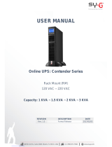
Rear panel view
Tower Models
IEC Type
T91i-2000
T91-2000

Xtreme Power Conversion Corporaon
T91 User’s Manual
Page 11
Uninterrupble Power Supply
Setup the UPS
Before installing the UPS, please read below to select proper locaon to install UPS.
1. UPS should be placed on the at and clean surface. Place it in an area away from vibraon,
dust, humidity, high temperature, ammable liquids, gases, corrosive and conducve contami-
nants. Install the UPS indoors in a clean environment, where it is away from window and door. Main-
tain minimum clearance of 100mm in the boom of the UPS to avoid dust and high temperature.
2. Maintain an ambient temperature range of 0ºC to 45ºC for UPS opmal operaon. For every 5ºC above 45ºC,
the UPS will derate 12% of nominal capacity at full load. The highest working temperature requirement for UPS
operaon is 50ºC.
3. It’s required to maintain maximum altude of 3505m to keep UPS normal operaon at full load UPS. If it’s used
in high altude area, please reduce connected load.
4. Place UPS:
It’s equipped with fan for cooling. Therefore, place the UPS in a well venlated area. It’s required to maintain
minimum clearance of 100mm in the front of the UPS and 300mm in the back and two sides of the UPS for heat
dissipaon and easy maintenance.
5. External baery connecon

Xtreme Power Conversion Corporaon
T91 User’s Manual
Page 12
Uninterrupble Power Supply
Step 1: External baery connecon
Reference the chart below to make the external baery connecon.
Step 2: UPS input connecon
Plug the UPS into a two-pole, three-wire, grounded receptacle only. Avoid using extension cords.
For 200/208/220/230/240VAC models: The power cord is supplied in the UPS package.
For 100/110/115/120/127VAC models: The power cord is aached to the UPS. The input plug is a NEMA
5-15P for 1K and 1.5K models, NEMA 5-20P for 2K model and NEMA 5-30P for 3K model.
Note: Check if the site wiring fault indicator lights up in LCD panel. It will be illuminated when the UPS is plugged
into an improperly wired ulity power outlet (Refer to Troubleshoong secon). Please also check if there is a cir-
cuit breaker against overcurrent and short circuit between the mains and AC input of the UPS for safety operaon.
The recommended protecon value as following:
For 200/208/220/230/240VAC models: 16A for the 2K model.
For 100/110/115/120/127VAC models: 15A for the 1K and 1.5K models, 20A for 2K model and 30A for 3K
model.
Step 3: UPS output connecon
There are two kinds of outputs: programmable outlets and general outlets. Please connect non-crical devices to
the programmable outlets and crical devices to the general outlets. During power failure, you may extend the
backup me to crical devices by seng shorter backup me for non-crical devices.
When connecng external baery packs, please be sure to connect polarity correctly. Connect posive pole of bat-
tery pack to posive pole of external baery connector in UPS and negave pole of baery pack to negave pole of
external baery connector in UPS. Polarity misconnecon will cause UPS internal fault. Please choose baery size
and connected numbers according to backup me requirement and UPS specicaons. To extend baery lifecycle,
it’s recommended to use them in the temperature range of 15ºC to 25ºC.

Xtreme Power Conversion Corporaon
T91 User’s Manual
Page 13
Uninterrupble Power Supply
Step 5: Network connecon
Network/Fax/Phone surge port
Connect a single modem/phone/fax line into surge-protected “IN” outlet on the back panel of the UPS unit. Con-
nect from “OUT” outlet to the equipment with another modem/fax/phone line cable.
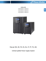
Step 6: Disable and enable EPO funcon
This UPS is equipped with EPO funcon. By default, the UPS is delivered from factory with Pin 1 and pin 2 closed
(a metal plate is connected to Pin 1 and Pin2) for UPS normal operaon. To acvate EPO funcon, remove two
screws on EPO port and metal plate will be removed.
Note: The EPO funcon logic can be set up via LCD seng. Please refer to program 16 in UPS
seng for the details
Step 7: Turn on the UPS
Press the ON/Mute buon on the front panel for two seconds to power on the UPS.
Note: The baery charges fully during the rst ve hours of normal operaon. Do not expect full baery run
capability during this inial charge period.
It’s in closed status for UPS
normal operaon as default.
To acvate EPO funcon,
remove these two screws.
Step 4: Communicaon connecon
Communicaon port:
USB port RS-232 port Intelligent slot
To allow for unaended UPS shutdown/start-up and status monitoring, connect the communicaon cable one
end to the USB/RS-232 port and the other to the communicaon port of your PC. With the monitoring soware
installed, you can schedule UPS shutdown/start-up and monitor UPS status through PC.
The UPS is equipped with intelligent slot perfect for either SNMP or AS400 card. When installing either SNMP or
AS400 card in the UPS, it will provide advanced communicaon and monitoring opons.

Xtreme Power Conversion Corporaon
T91 User’s Manual
Page 14
Uninterrupble Power Supply
Step 8: Install soware
For opmal computer system protecon, install UPS monitoring soware to fully congure UPS shutdown. Use
supplied RS-232 or USB communicaon cable to connect RS-232/USB port of UPS and RS-232/USB port of PC.
Then, follow below steps to install monitoring soware.
1. Insert the included installaon CD into CD-ROM drive and then follow the on-screen instrucons to proceed
soware installaon. If no screen shows 1 minute aer inserng the CD, please execute setup.exe le for iniat-
ing soware installaon.
2. Follow the on-screen instrucons to install the soware.
3. When your computer restarts, the monitoring soware will appear as an orange plug icon located in the sys-
tem tray, near the clock.
Buon Funcon
ON/Mute
Buon
- Turn on the UPS: Press and hold ON/Mute buon for at least 2 seconds to turn on the
UPS.
- Mute the alarm: Aer the UPS is turned on in baery mode, press and hold this buon
for at least 3 seconds to disable or enable the alarm system. But it’s not applied to the
situaons when warnings or errors occur.
- Up key: Press this buon to display previous selecon in UPS seng mode.
- Switch to UPS self-test mode: Press ON/Mute buons for 3 seconds to enter UPS self-
tesng while in AC mode, ECO mode, or converter mode.
OFF/Enter
Buon
- Turn o the UPS: Press and hold this buon at least 2 seconds to turn o the UPS. UPS
will be in standby mode under power normal or transfer to Bypass mode if the Bypass
enable seng by pressing this buon.
- Conrm selecon key: Press this buon to conrm selecon in UPS seng mode.
Select
Buon
- Switch LCD message: Press this buon to change the LCD message for input voltage, in-
put frequency, input current, baery voltage, baery current, baery capacity, ambient
temperature, output voltage, output frequency, load current and load percent.
- Seng mode: Press and hold this buon for 3 seconds to enter UPS seng mode when
Standby and Bypass mode.
- Down key: Press this buon to display next selecon in UPS seng mode.
ON/Mute
+ Select
Buon
- Switch to bypass mode: When the main power is normal, press ON/Mute and Select
buons simultaneously for 3 seconds. Then UPS will enter to bypass mode. This acon
will be ineecve when the input voltage is out of acceptable range.
- Exit seng mode or return to the upper menu: When working in seng mode, press
ON/Mute and Select buons simultaneously for 0.2 seconds to return to the upper
menu. If it’s already in top menu, press these two buons at the same me to exit the
seng mode.
Operaons
Buon operaon

Xtreme Power Conversion Corporaon
T91 User’s Manual
Page 15
Uninterrupble Power Supply
Display Funcon
Backup me informaon
Indicates the esmated backup me.
H: hours, M: minute, S: second.
Conguraon and fault informaon
Indicates the conguraon items, and the conguraon items are listed in details in secon 3-5.
Indicates the warning and fault codes, and the codes are listed in details in secon 3-7 and 3-8.
Mute operaon
Indicates that the UPS alarm is disabled.
Input, Baery, Temperature, Output & Load informaon
Indicate the input voltage, input frequency, input current, baery voltage, baery current,
baery capacity, ambient temperature, output voltage,
output frequency, load current and load percent.
k: kilo, W: wa, V: voltage, A: ampere, %: percent, C: cengrade degree, Hz: frequency
Indicates the load level by 0-24%, 25-49%, 50-74% and 75-100%.
Indicates overload.
Programmable outlets informaon
Indicates that programmable management outlets are working.
Mode operaon informaon
Indicates the UPS connects to the mains.
Indicates the baery is working.
Indicates charging status
Indicates the bypass circuit is working.
LCD Panel

Xtreme Power Conversion Corporaon
T91 User’s Manual
Page 16
Uninterrupble Power Supply
Display Funcon
Indicates the ECO mode is enabled.
Indicates the AC to DC circuit is working.
Indicates the PFC circuit is working.
Indicates the inverter circuit is working.
Indicates the UPS is working in converter mode.
Indicates the output is working.
Baery informaon
Indicates the baery level by 0-24%, 25-49%, 50-74%, and 75-100%.
Indicates low baery.
Audible Alarm
Baery Mode Sounding every 5 seconds
Low Baery Sounding every 2 seconds
Overload Sounding every second
Fault Connuously sounding
Bypass Mode Sounding every 10 seconds

Xtreme Power Conversion Corporaon
T91 User’s Manual
Page 17
Uninterrupble Power Supply
LCD display wordings index
Abbreviaon Display content Meaning
ENA
Enable
DIS
Disable
ESC
Escape
HLS
High loss
LLS
Low loss
AO
Acve open
AC
Acve close
EAT
Esmated autonomy me
RAT
Running autonomy me
SD
Shutdown
OK
OK
ON
ON
BL
Baery Low
OL
Over Load
OI
Over input current
NC
Baery No Connect
OC
Over Charge
SF
Site wiring fault
EP
EPO
TP
Temperature
CH
Charger
BF
Baery Fault
BV
Bypass Out Range
FU
Bypass frequency unstable
BR
Baery Replace
EE
EEPROM error

Xtreme Power Conversion Corporaon
T91 User’s Manual
Page 18
Uninterrupble Power Supply
UPS Seng
01: Output voltage seng
Parameter 1 Parameter 2
There are two parameters to set up the UPS.
Parameter 1: It’s for program alternaves. Refer to below
table.
Parameter 2 is the seng opons or values
for each program.
Interface
Sengs
Parameter 2: Output voltage
For 200/208/220/230/240 VAC models, you may choose the following
output voltage:
200: presents output voltage is 200Vac
208: presents output voltage is 208Vac
220: presents output voltage is 220Vac
230: presents output voltage is 230Vac (Default)
240: presents output voltage is 240Vac
For 100/110/115/120/127 VAC models, you may choose the following
output voltage:
100: presents output voltage is 100Vac
110: presents output voltage is 110Vac
115: presents output voltage is 115Vac
120: presents output voltage is 120Vac (Default)
127: presents output voltage is 127Vac
02: Frequency Converter enable/disable
Interface
Sengs
Parameter 2: Enable or disable converter mode. You may choose the
following two opons:
CF ENA: converter mode enable
CF DIS: converter mode disable (Default)

Xtreme Power Conversion Corporaon
T91 User’s Manual
Page 19
Uninterrupble Power Supply
Interface
Sengs
Parameter 2: Output frequency seng.
You may set the inial frequency on baery mode:
BAT 50: presents output frequency is 50Hz
BAT 60: presents output frequency is 60Hz
If converter mode is enabled, you may choose the following output fre-
quency:
CF 50: presents output frequency is 50Hz
CF 60: presents output frequency is 60Hz
04: ECO enable/disable
Interface
Sengs
Parameter 2: Enable or disable ECO funcon. You may choose the fol-
lowing two opons:
ENA: ECO mode enable
DIS: ECO mode disable (Default)
05: ECO voltage range seng
Interface
Sengs
Parameter 2: Set the acceptable high voltage point and low voltage
point for ECO mode by pressing Down key or Up key.
HLS: High loss voltage in ECO mode in parameter 2.
For 200/208/220/230/240 VAC models, the seng range in parameter 3
is from +7V to +24V of the nominal voltage. (Default: +12V)
For 100/110/115/120/127 VAC models, the seng range in parameter 3
is from +3V to +12V of the nominal voltage. (Default: +6V)
LLS: Low loss voltage in ECO mode in parameter 2.
For 200/208/220/230/240 VAC models, the seng range in parameter 3
is from -7V to -24V of the nominal voltage. (Default: -12V)
For 100/110/115/120/127 VAC models, the seng voltage in parameter
3 is from -3V to -12V of the nominal voltage. (Default: -6V)

Xtreme Power Conversion Corporaon
T91 User’s Manual
Page 20
Uninterrupble Power Supply
Interface
Sengs
Parameter 2: Enable or disable Bypass funcon. You may choose the
following two opons:
ENA: Bypass enable
DIS: Bypass disable (Default)
07: Bypass voltage range seng
06: Bypass enable/disable when UPS is o
Interface
Sengs
Parameter 2: Set the acceptable high voltage point and acceptable low
voltage point for Bypass mode by pressing the Down key or Up key.
HLS: Bypass high voltage point
For 200/208/220/230/240 VAC models:
230-264: seng the high voltage point in parameter 3 from 230Vac to
264Vac. (Default: 264Vac)
For 100/110/115/120/127 VAC models:
120-140: seng the high voltage point in parameter 3 from 120Vac to
140Vac. (Default: 132Vac)
LLS: Bypass low voltage point
For 200/208/220/230/240 VAC models:
170-220: seng the low voltage point in parameter 3 from 170Vac to
220Vac. (Default: 170Vac) For 100/110/115/120/127 VAC models:
85-115: seng the low voltage point in parameter 3 from 85Vac to
115Vac. (Default: 85Vac)
/