
BTKIT
110105.04
NEDERLANDS 2
ENGLISH 9
DEUTSCH 15
FRANÇAIS 21
ESPAÑOL 27
ITALIANO 33
Copyright © 2019 Vetus b.v. Schiedam Holland
Installatie instructies en
eigenaarshandleiding
Aansluitkit voor vuilwatertanks
Installation instructions and
owner's manual
Connection kit for waste water tanks
Einbauanleitung und
Handbuch für den Eigentümer
Anschlußbausätze für Schmutzwassertanks
Instructions d’installation et
mode d’emploi destiné au propriétaire
Kits de raccordement pour réservoirs
d'eaux usées
Instrucciones de instalación y
manual del propietario
Equipo de conexión para depósitos
de aguas sucias
Istruzioni per l’installazione e
manuale per l’utente
Kit di allacciamento per serbatoi
dell'acqua reua
Connection kit for waste water tanks

2 110105.04
Connection kit for waste water tanks
1 Inleiding . . . . . . . . . . . . . . . . . . . . . . . . . 3
2 Installatie
. . . . . . . . . . . . . . . . . . . . . . . . 3
2.1 Algemeen . . . . . . . . . . . . . . . . . . . . . . . . 3
2.2 Montage inspectiedeksel en
ttingen . . . . . . . . . . . . . . . . . . . . . . . . . 4
2.3 Aansluiten van de tank . . . . . . . . . . . . 6
2.4 Controle . . . . . . . . . . . . . . . . . . . . . . . . . 6
3 Gebruik
. . . . . . . . . . . . . . . . . . . . . . . . . . 7
4 Winterklaar maken
. . . . . . . . . . . . . . . 7
5 Onderhoud
. . . . . . . . . . . . . . . . . . . . . . 7
6 Technische gegevens
. . . . . . . . . . . . . 8
1 Einleitung
. . . . . . . . . . . . . . . . . . . . . . . 15
2 Installation
. . . . . . . . . . . . . . . . . . . . . . 15
2.1 Allgemeines . . . . . . . . . . . . . . . . . . . . . 15
2.2 Montage des Mannlochdeckels
und Fittingen. . . . . . . . . . . . . . . . . . . . 16
2.3 Anschließen des Tanks . . . . . . . . . . . 18
2.4 Kontrolle . . . . . . . . . . . . . . . . . . . . . . . . 18
3 Benutzung
. . . . . . . . . . . . . . . . . . . . . . 19
4 Winterfest machen
. . . . . . . . . . . . . . 19
5 Wartung
. . . . . . . . . . . . . . . . . . . . . . . . 19
6 Technische Daten
. . . . . . . . . . . . . . . 20
1 Introducción
. . . . . . . . . . . . . . . . . . . . 27
2 Instalación
. . . . . . . . . . . . . . . . . . . . . . 27
2.1 En general. . . . . . . . . . . . . . . . . . . . . . . 27
2.2 Montaje de la tapa del pozo de
acceso y accesorios de tubo . . . . . . 28
2.3 Conectar el tanque . . . . . . . . . . . . . . 30
2.4 Comprobación . . . . . . . . . . . . . . . . . . 30
3 Uso
. . . . . . . . . . . . . . . . . . . . . . . . . . . . . 31
4 Preparación para el invierno
. . . . . 31
5 Mantenimiento
. . . . . . . . . . . . . . . . . 31
6 Especicaciones técnicas
. . . . . . . . 32
1 Introduction
. . . . . . . . . . . . . . . . . . . . . 9
2 Installation
. . . . . . . . . . . . . . . . . . . . . . . 9
2.1 General . . . . . . . . . . . . . . . . . . . . . . . . . . 9
2.2 Fitting the inspection cover and
ttings . . . . . . . . . . . . . . . . . . . . . . . . . . 10
2.3 Tank connections . . . . . . . . . . . . . . . . 12
2.4 Check . . . . . . . . . . . . . . . . . . . . . . . . . . . 12
3 Use
. . . . . . . . . . . . . . . . . . . . . . . . . . . . . 13
4 Making ready for winter
. . . . . . . . . 13
5 Maintenance
. . . . . . . . . . . . . . . . . . . . 13
6 Technical details
. . . . . . . . . . . . . . . . 14
1 Introduction
. . . . . . . . . . . . . . . . . . . . 21
2 Installation
. . . . . . . . . . . . . . . . . . . . . . 21
2.1 Généralités . . . . . . . . . . . . . . . . . . . . . . 21
2.2 Montage du couvercle de visite et
des garnitures . . . . . . . . . . . . . . . . . . . 22
2.3 Raccordement du réservoir. . . . . . . 24
2.4 Contrôle . . . . . . . . . . . . . . . . . . . . . . . . 24
3 Utilisation
. . . . . . . . . . . . . . . . . . . . . . 25
4 Remisage pour l’hiver
. . . . . . . . . . . 25
5 Entretien
. . . . . . . . . . . . . . . . . . . . . . . . 25
6 Fiche technique
. . . . . . . . . . . . . . . . . 26
1 Introduzione
. . . . . . . . . . . . . . . . . . . . 33
2 Installazione
. . . . . . . . . . . . . . . . . . . . 33
2.1 Generalità . . . . . . . . . . . . . . . . . . . . . . . 33
2.2 Montaggio del coperchio del
passo d’uomo e dei raccordi . . . . . . 34
2.3 Allacciamento del serbatoio . . . . . . 36
2.4 Controlli. . . . . . . . . . . . . . . . . . . . . . . . . 36
3 Uso
. . . . . . . . . . . . . . . . . . . . . . . . . . . . . 37
4 Preparazione per il rimessaggio
. 37
5 Manutenzione
. . . . . . . . . . . . . . . . . . 37
6 Dati tecnici
. . . . . . . . . . . . . . . . . . . . . . 38
Inhoud Content Inhalt
Sommaire Índice Indice
7 Hoofdafmetingen . . . . . . . . . . . . . . . 39
7 Hauptabmessungen
. . . . . . . . . . . . 39
7 Dimensiones principales
. . . . . . . . 39
7 Principal dimensions
. . . . . . . . . . . . 39
7 Dimensions principales
. . . . . . . . . . 39 7 Dimensioni principal . . . . . . . . . . . . 39
Page is loading ...
Page is loading ...
Page is loading ...
Page is loading ...
Page is loading ...
Page is loading ...

110105.04 9
Connection kit for waste water tanks
ENGLISH
W
WW
WW
F
F
W
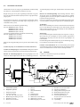
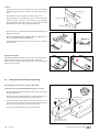
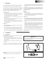
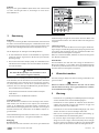
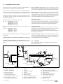
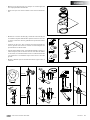
2 Installation
1 Introduction
These instructions apply for the connection kit for the Vetus rigid
plastic waste water tanks for grey water and black water.
When installing a waste water tank, the European Recreational Craft
Directive (RCD, 2013/53/EU) and any national legislation must be ob-
served. Use the ISO 8099 standard as a guide.
Grey water tank
- A grey water tank should only be used for collecting water from
the sink, shower, wash basin, air conditioning, etc..
- The capacity of a waste water tank can never be too large.
- Match the capacity to the amount of fresh water available; the
capacity of the water tank(s).
- Fit sink, shower, wash basin, etc. with a drain with sieve, so that
coarse waste, such as hair etc., will be less likely to enter the grey
water tank.
Black water tank
- A black water tank is used only for temporary collecting toilet
waste.
- The capacity of a waste water tank can never be too great.
- The capacity should be calculated using the amount of ushing
water (outside water) used by the toilet. Reckon on 7 to 14 litres
(1.5 to 3 Imp. Gal., 1.9 to 3.8 US Gal.) of black water per person
per day.
Instead of just one grey water tank, it is also possible to distribute the
total capacity required over two or more tanks.
Arrange the tanks, and thus the weight, evenly over the ship.
(F = Fuel, W = Water, WW = Waste Water)
Note
Position the tank in such a way that the plug P is on the top
side of the tank. Consult the diagrams on p. 39 for placement
of plug P.
- Use only water-soluble toilet paper to prevent unnecessary block-
ages. Sanitary towels and tampons in the toilet and black water
tank will certainly cause blockages.
Clearing a blockage is an unpleasant job, make sure you have a pair
of rubber gloves on board.
Smell
Grey water tank
- Unpleasant odours will be produced in every grey water tank. Fit
the sink, shower, wash basin, etc., with an S-bend (siphon or stink
trap) and a plug.
Black water tank
- Unpleasant smells caused by faeces will be produced in every
blackwater tank. The use of sea water for ushing will increase the
smell. The algae in sea water also produce unpleasant smells.
- It is possible to add special additives to waste water tanks to re-
duce the smell, called tank deodorants. A simple way of reducing
the smell is by using washing soda, which cleans and sterilizes.
- Leaking hoses, hose ttings, tanks, tank covers, etc., can also cause
a smell nuisance. So carry out a regular check of the whole system.
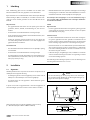
For dimensions, see drawing on page 39. Tolerances of +/- 2% apply
to all tank dimensions!
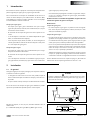
2.1 General
When choosing a place for the tank and for the deck ller cap, take
the following into account:
- The suction hose should be as short as possible, must go directly
down to the tank and be as straight as possible.
- The space in which the tank is placed should be properly venti-
lated.

10 110105.04
Connection kit for waste water tanks
ø 115 (
11
/
32
”)
ø 6 (
1
/
4
”)
10 (
3
/
8
”)
140 (5
1
/
2
”)
P.C.D. 136 (5
3
/
8
”)
P
MIN. 85 mm (3
3
/
8
˝)
ø 57 mm (2
1
/
4
˝)
ø 43 mm (1
11
/
16
˝)
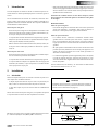
Fitting in sailing ships
When tting remember that the suction waste water hose must al-
ways be positioned on the same side of the ship as the tank.
This prevents too high a pressure from possibly occurring in the tank
when sailing at an angle.
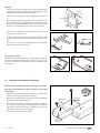
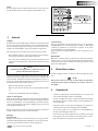
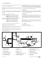
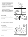
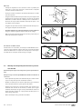
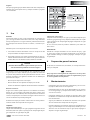
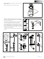
2.2 Fitting the inspection cover and ttings
Always t the inspection cover on the top of the tank!
Position the connector lid preferably where plug P is located.
• Use the drill stencil supplied to make the hole for the cover. Finish
the hole free of burrs.
• Drill the holes for the ttings (43 mm (111∕16”) diameter) and suc-
tion tube (57 mm (21∕4”) diameter) in the top of the tank.
• Choose the position of the ttings so that when the ship is bea-
ched on its side, waste water cannot run back to the shower, wash
basin, toilet, etc., or ow outside via the tank air-relief.
• Clean saw dust and drill shavings from inside the tank.
± 30 mm (1
3
/
16
˝)
70 mm (2
3
/
4
˝)
70 mm (2
3
/
4
˝)
Position
• Position the tank as close as possible to the toilet to avoid dirty
water owing back into the toilet from the tank when the boat
heels.
• Install the tank so that it is easily accessible for inspection.
• Also ensure that there is sucient free space over the top of the
tank for the hose connections. These must be easily accessible
during installation. The tank should be 1 cm (3/8") free all round
from bulkheads or other tanks, to provide ventilation.
• Ensure that there is a suciently solid foundation for placing and
xing the tank rmly.
• The size of the tank increases slightly when it is full. Take this
into account when xing the tank in place.
• Use the xing straps from the connection kit as these allow the
tank to expand.

110105.04 11
Connection kit for waste water tanks
ENGLISH
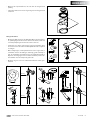
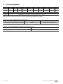
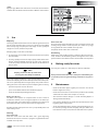
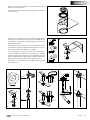
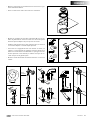
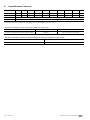
• Fit the inspection cover in the tank using the gasket supplied.
• Screw the cover tight against the backing ring using the screws
supplied.
• Assemble the ttings (A) and the suction tube (B) with the gas-
ket rings supplied. Tighten the nuts using the wrench, never with
water-pump pliers. Do not tighten the nuts excessively.
• Consult the diagrams on the next page for installation of the
exhaust pipe.
• After 2 days check that the connector nuts are still tight, tighten
more securely if required. Repeat this after 4 days.
• To prevent blockages caused by hairs and coarse waste in parti-
cular, all ttings should have burrs removed internally, local nar-
rowing should be reduced to a minimum and any changes in pipe
diameter should be done using conical adapters or large radii.
• Fit the sender for a waste water level meter, if tted
ø 43 mm (1
11
/
16
˝)
2
1
O-ring O-ring
3
O-ring
O-ring
B
O-ring
O-ring
O-ring
O-ring
4
15˚
15 mm (
9
/
16
")
ø 57 mm
(2
1
/
4
")
5 6
A

12 110105.04
Connection kit for waste water tanks
1
20
9
10
11
12
13
14
15
16
17
18
19
21
14
min. 40 cm
(16”)
9
1
2
3
4 5
6
7
8
10
11
12
13
14
15
16
17
18
19
20
21
8
14
17
17
22
min. 40 cm
(16”)
1 2
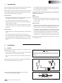
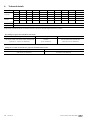
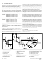
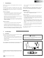
2.3 Tank connections
Connect the tank with a good quality reinforced hose. Avoid sharp
bends and kinks or sagging in the hose.
Bracket the hose at not too far apart, regular points, to prevent the
hose sagging. Deposits will collect in these sags, causing a blockage
after time.
The reinforced hose should be an odour-proof waste water hose
and resistant to a limited under- and over-pressure of 30 kPa (0,3
bar, 4 psi).
Vetus supplies a hose suitable for waste water.
Article Code: WWHOSE16A, 16 mm (5/8”) internal diameter
WWHOSE19A, 19 mm (3/4”) internal diameter
WWHOSE25A, 25 mm (1”) internal diameter
WWHOSE38A, 38 mm (1 1/2”) internal diameter
Specially for black water tanks, odour-proof waste water hose:
Article Code: SAHOSE16, 16 mm (5/8”) internal diameter
SAHOSE19, 19 mm (3/4”) internal diameter
SAHOSE25, 25 mm (1”) internal diameter
SAHOSE38, 38 mm (1 1/2”) internal diameter
Fit every hose connection with a good stainless steel hose clip.
Install pump ‘10’ and hull outlet with valve ‘12’.
Install the suction hose(s) ‘17’ (ø 38mm, 1 1/2" dia.) such that neither
the tank, pump or deck cap are subject to any mechanical loads.
Fit the air-relief nipple ‘14’ as high up as possible above the level of
the top of the tank. Choose a place for the nipple where rain or other
outside water cannot enter.
1. ‘Black water’ system
2. ‘Grey water’ system
1. Waste water tank
2. Tapered connection,
ø 16, ø 19, ø 25 and ø 38 mm
3. Vent connection, ø 19 mm
4. Suction pipe: ø 38 mm
5. Indicator for level meter
Fit the air-relief pipe ‘18’, internal diameter 16 (5/8") , 19 (3/4") , 25
(1") or 38 mm (1 1∕2”) between the air-relief nipple and the tank. When
viewed from the tank, the air-relief pipe should run straight upwards.
It is very advisable to t a smell lter '15' type NSF in the pipe. This
prevents unpleasant smells from the vent nipple.
Rinsing pipe ‘23’
In order to rinse out the tank easily with clean water, and extra tting
can be made in the deck connected to an extra deck cap. Clean water
can be poured in through this pipe.
Discharge pump
A non-priming waste water pump must be tted lower than, or at
the same height as the underside of the tank. The connection for the
pump in the tank must therefore be as low as possible in the tank.
A self-priming pump can be mounted at any height in relation to the
tank.
Install an air vent ‘11’ in the discharge pipe between pump and hull
outlet when the waste water tank is below the water line and the hull
outlet is also below the water line.
2.4 Check
Check the system for any leaks.
Extraction pressure 20 kPa (0.2 bar, 3psi).
6. Washbasin
7. Shower
8. Siphon (Smell trap)
9. Toilet
10. Waste water pump
11. Bend aerator
1
2. Hull lead-through with shut-o valve
13. Hull lead-through ø 8 mm
14. Vent nipple: ø 19 mm
15. Smell lter: ø 19, ø 25, ø 38 mm
16. Deck cap for suction
17. Suction waste water hose: ø 38 mm
18. Vent pipe, ø 19 mm
19. Vent pipe: ø 8 mm
20. Tapered waste water hose
ø 16, ø 19, ø 25 and ø 38 mm
21. Three-way valve
22. Rinsing pipe

110105.04 13
Connection kit for waste water tanks
ENGLISH
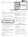
3 Use
‘Black water’ tank
Clean the inside of the tank with water and a good toilet cleaner; add
cleaning vinegar if there are lime deposits; use a brush or a sponge
for a rigid tank. Rinse the tank with clean tap water.
If required, add to reduce odors 'Tank Fresh'.
Disinfecting
Disinfect the tank by lling it with a solution of bleach in water (1:
1000). Circulate this disinfecting mixture through the waste water
system. Remove the solution and rinse the tank with clean tap water.
4 Making ready for winter
The tank, pipes, pump, etc. must always be drained completely.
Note
Never put anti-freeze in the tank or other parts of the drinking wa-
ter system to protect it against freezing, anti-freeze is very poison-
ous!
5 Maintenance
- Check the breather nipple regularly and clean the sieve of the
breather nipple if necessary.
- Check the hoses and hose connections for possible leaks annually
and t new hoses and/or hose clamps as necessary.
- Also check the tank for damage as a result of chang. Replace a
damaged tank immediately.
- Carry out the disinfection procedures described under ‘Use’ at the
beginning of the sailing season.
- A tank and installation that is strongly contaminated by algae can
be cleaned by rinsing the tank, the pump and pipes with a solu-
tion of bleach in water (1:20). Rinse the tank with clean tap water.
Fresh water tank
• Drinking water safe• Meets KTW standard
• P max. 30 kPa (0.3 bar | 4.35 psi)
• Tank capacity of:
AT147583W.VE
Quality product by
vetus
, Schiedam
Designed and made in the Netherlands
Excellent
warranty
Worldwide
network
Diesel fuel tank
• According to ISO 21487
• 0613
AT147583F.VE
• Max. test pressure 30 kPa (0.3 bar | 4.35 psi)
• Tank capacity of:
• Max. 100 °C
• Max. ll-up height 3.5 m
Quality product by vetus, Schiedam
Designed and made in the Netherlands
Excellent
warranty
Worldwide
network
Waste water tank
• According to ISO 8099
• P max. 30 kPa (0.3 bar | 4.35 psi)
• 0613
• Tank capacity of:
AT147583B.VE
Quality product by vetus, Schiedam
Designed and made in the Netherlands
Excellent
warranty
Worldwide
network
42 litres
9.2 Imp.Gal. | 11.1 US Gal.
61 litres
13.4 Imp.Gal. | 16.1 US Gal.
88 litres
19.4 Imp.Gal. | 23.2 US Gal.
170 litres
37.4 Imp.Gal. | 44.9 US Gal.
215 litres
47.3 Imp.Gal. | 56.8 US Gal.
335 litres
73.7 Imp.Gal. | 88.5 US Gal.
110 litres
24.2 Imp.Gal. | 29 US Gal.
390 litres
85.8 Imp.Gal. | 103 US Gal.
xx litres
xx.x Imp.Gal. | xx.x US Gal.
xx litres
xx.x Imp.Gal. | xx.x US Gal.
100 litres
22 Imp.Gal. | 26.4 US Gal.
xx litres
xx.x Imp.Gal. | xx.x US Gal.
137 litres
30.1 Imp.Gal. | 36.2 US Gal.
xx litres
xx.x Imp.Gal. | xx.x US Gal.
AT147583A.VE
Waste water tank
• According to ISO 8099
• P max. 30 kPa (0.3 bar | 4.35 psi)
• 0613
• Tank capacity of:
AT147583B.VE
Quality product by vetus, Schiedam
Designed and made in the Netherlands
Excellent
warranty
Worldwide
network
xx litres
xx.x Imp.Gal. | xx.x US Gal.
S
ticker
Apply the grey ‘Waste water tank’ sticker on the tank, the text must be
readable after installation of the tank and also ax the content sticker.
Emptying
The longer polluted water has been in the tank the greater the risk of
nuisance from smell. Therefore, never leave a waste water tank lled
unnecessarily long, but pump the tank empty or have it pumped
empty once a week, or whenever possible.
Pumping empty can be done in two ways:
1. by connecting a shore pump-out system to the deck cap to pump
the tank empty.
2. by using a pump present on the ship to pump out the waste water
directly overboard through the deck cap and a hose connected
to this. This pump must have internal diameter of minimum ø 38
mm (1½ inch).
Note
Pumping waste water directly overboard is
in many places absolutely not allowed!
If the tank is pumped empty by a high capacity pump there is a risk
of the tank collapsing due to the reduced pressure caused. This prob-
lem occurs particularly when using the pump-out systems. The fol-
lowing measures can be taken to prevent collapsing from occurring:
- open the inspection cover on the tank
- open a shut-o valve tted to the tank for this purpose
- install an automatically working blow valve.
During your absence
The water in the siphons can evaporate when no use is made of
washbasins, showers etc. for a long time (siphons act as smell traps
in the pipes). This causes smell nuisance. Therefore, place plugs in all
drains when the ship is not to be manned for a longer period.
Disinfect the tank and pipes at least once a year preferably at the end
of the sailing season.
Cleaning
‘Grey water’ tank
Clean the inside of the tank with water and a good degreasing
household cleaner; use a brush or a sponge for a rigid tank. Rinse the
tank with clean tap water.

14 110105.04
Connection kit for waste water tanks
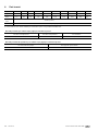
6 Technical details
Hose fittings for grey water tanks/black water tanks:
for filling hose for discharge hose for air relief
ø 16 mm, ø 19 mm, ø 25 mm, ø 35 mm and ø 38 mm
(5/8”, 3/4”, 1”, 1 3/8”, 1 1/2” diameter)
ø 38 mm
(1 1/2” diameter)
ø 16, ø 19 mm, ø 25 and ø 38 mm
(5/8”, 3/4”, 1” 1 1/2” diameter)
Fittings for hose with suction tube for grey water tanks/black water tanks:
for pump connection for Vetus waste water deck cap
ø 38 mm (1 1/2” diameter) ø 38 mm (1 1/2” diameter)
Type ATANK42 ATANK61 TANK88 ATANK110 ATANK137 ATANK170 ATANK215 ATANK335 ATANK390
Capacity
42 61 88 110 137 170 215 335 390 liter *)
9.2 13.4 19.4 24.2 30.1 37.4 47.3 73.7 85.8 Imp. Gallon *)
11.1 16.1 23.2 29 36.2 44.9 56.8 88.5 103 US Gallon *)
Weight
3.0 4.0 6.7 7.5 9.25 11.4 13.6 25.8 26.6 kg *)
6.6 8.8 14.8 16.5 20.4 25.1 30 56.9 58.6 lbs *)
Max. pressure
30 kPa (0.3 bar, 4.4 psi)
Material mMPE (Metallocene Medium Density Polyethylene), colour : blue
*) The values stated in the Table are nominal values for capacity and weight. Slight deviation is possible.
Page is loading ...
Page is loading ...
Page is loading ...
Page is loading ...
Page is loading ...
Page is loading ...
Page is loading ...
Page is loading ...
Page is loading ...
Page is loading ...
Page is loading ...
Page is loading ...
Page is loading ...
Page is loading ...
Page is loading ...
Page is loading ...
Page is loading ...
Page is loading ...
Page is loading ...
Page is loading ...
Page is loading ...
Page is loading ...
Page is loading ...
Page is loading ...

110105.04 39
Connection kit for waste water tanks
460
(18
1
/
8
”)
P
350
(13
3
/
4
”)
290
(11
7
/
16
”)
660
(26”)
350
(13
3
/
4
”)
290
(11
7
/
16
”)
P
P
1200
(47
1
/
4
”)
350
(13
3
/
4
”)
290
(11
7
/
16
”)
P
600
(23
5
/
8
”)
1000
(39
3
/
8
”)
400
(15
3
/
4
”)
P
1100
(43
5
/
16
”)
440
(17
5
/
16
”)
400
(15
3
/
4
”)
130
(5
1
/
8
”)
P
1700
(67”)
700
(27
9
/
16
”)
350
(13
3
/
4
”)
400
(15
3
/
4
”)
400
(15
3
/
4
”)
200
(7
7
/
8
”)
P
800
(31
1
/
2
”)
1400
(55
1
/
8
”)
400
(15
3
/
4
”)
800
(31
1
/
2
”)
400
(15
3
/
4
”)
330
(13”)
P
P
1200
(47
1
/
4
”)
400
(15
3
/
4
”)
330
(13”)
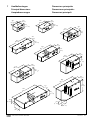
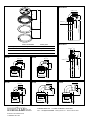
7 Hoofdafmetingen
Principal dimensions
Hauptabmessungen
Dimensions principales
Dimensiones principales
Dimensioni principali

1
2
Service onderdelen Service parts
pos. qty part benaming description
1 1 WTK02 Inspectiedeksel Inspection lid
2 1 BTKIT Inspectiedeksel kit Inspection lid kit
MAX. 8 (
5
/
16
“)
MAX. 8 (
5
/
16
“)
780 (30
11
/
16
“)
780 (30
11
/
16
“)
63
(2
1
/
2
“)
80 (3
1
/
8
“)
ø 56
(2
3
/
16
“)
ø 56
(2
3
/
16
“)
ø 38
(1
1
/
2
“)
ø 38
(1
1
/
2
“)
MAX. 8 (
5
/
16
“)
MAX. 8 (
5
/
16
“)
780 (30
11
/
16
“)
780 (30
11
/
16
“)
63
(2
1
/
2
“)
80 (3
1
/
8
“)
ø 56
(2
3
/
16
“)
ø 56
(2
3
/
16
“)
ø 38
(1
1
/
2
“)
ø 38
(1
1
/
2
“)
MAX. 12 (
1
/
2
“)
MIN. 3 (
1
/
8
“)
ø 42
(1
5
/
8
“)
ø 60 (2
3
/
8
“)
51(2 “)
16 (
5
/
8
“)
51(2 “)
MAX. 12 (
1
/
2
“)
MIN. 3 (
1
/
8
“)
ø 42
(1
5
/
8
“)
ø 60 (2
3
/
8
“)
13 (
1
/
2
“)
MAX. 12 (
1
/
2
“)
MIN. 3 (
1
/
8
“)
ø 42
(1
5
/
8
“)
ø 60 (2
3
/
8
“)
51(2 “)
19 (
3
/
4
“)
MAX. 12 (
1
/
2
“)
MIN. 3 (
1
/
8
“)
ø 42
(1
5
/
8
“)
ø 60 (2
3
/
8
“)
59 (2
5
/
16
“)
38 (1
1
/
2
“)
MAX. 12 (
1
/
2
“)
MIN. 3 (
1
/
8
“)
ø 42
(1
5
/
8
“)
ø 60 (2
3
/
8
“)
59 (2
5
/
16
“)
25 (1“)
vetus b.v.
FOKKERSTRAAT 571 - 3125 BD SCHIEDAM - HOLLAND
TEL.: +31 0(0)88 4884700 - sales@vetus.nl - www.vetus.com
Printed in the Netherlands
110105.04 2019-05
RT13B
RT25BRT19B
RT16B
RT38B
WTS78038B
WTS78038S
-
 1
1
-
 2
2
-
 3
3
-
 4
4
-
 5
5
-
 6
6
-
 7
7
-
 8
8
-
 9
9
-
 10
10
-
 11
11
-
 12
12
-
 13
13
-
 14
14
-
 15
15
-
 16
16
-
 17
17
-
 18
18
-
 19
19
-
 20
20
-
 21
21
-
 22
22
-
 23
23
-
 24
24
-
 25
25
-
 26
26
-
 27
27
-
 28
28
-
 29
29
-
 30
30
-
 31
31
-
 32
32
-
 33
33
-
 34
34
-
 35
35
-
 36
36
-
 37
37
-
 38
38
-
 39
39
-
 40
40


Ask a question and I''ll find the answer in the document
Finding information in a document is now easier with AI
in other languages
- italiano: Vetus BTKIT Guida d'installazione
- français: Vetus BTKIT Guide d'installation
- español: Vetus BTKIT Guía de instalación
- Deutsch: Vetus BTKIT Installationsanleitung
- Nederlands: Vetus BTKIT Installatie gids
Related papers
-
Vetus ILTCONW Installation guide
-
Vetus Complete tank type WWS Installation guide
-
-
-
-
-
-
-
-
Other documents
-
Dometic Kampa Portaflush 10, Portaflush 20 Operating instructions
-
Renkforce 1526585 Owner's manual
-
-
Renkforce 1529147 Owner's manual
-
-
-
-
-
Renkforce 1526586 User manual
-