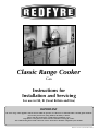
Redfyre Redfyre Classic Range Gas tech manual Owner's manual
- Category
- Fireplaces
- Type
- Owner's manual
This manual is also suitable for
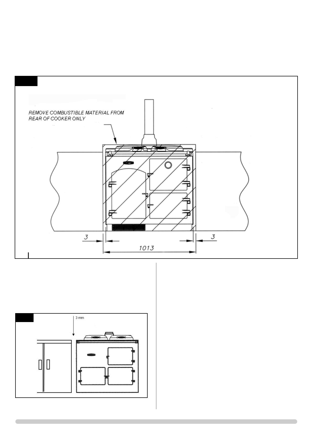
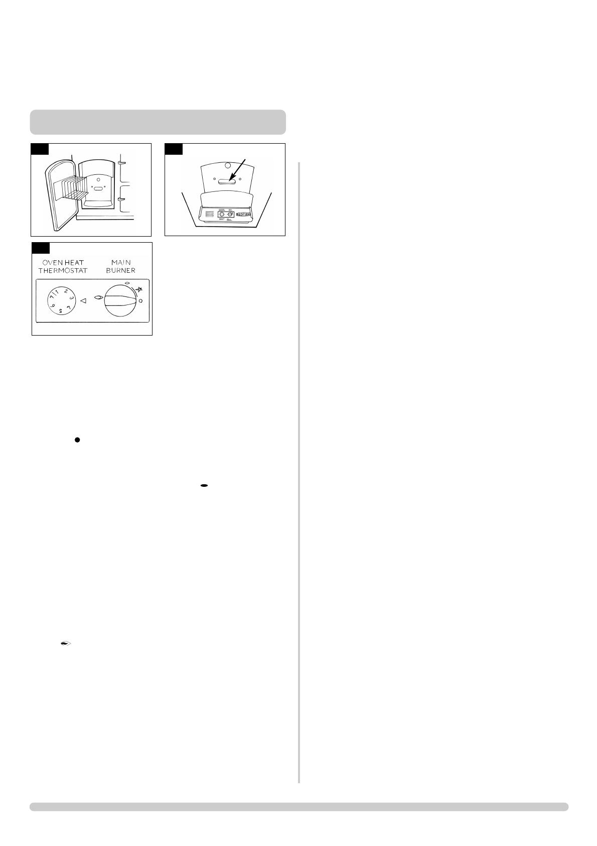
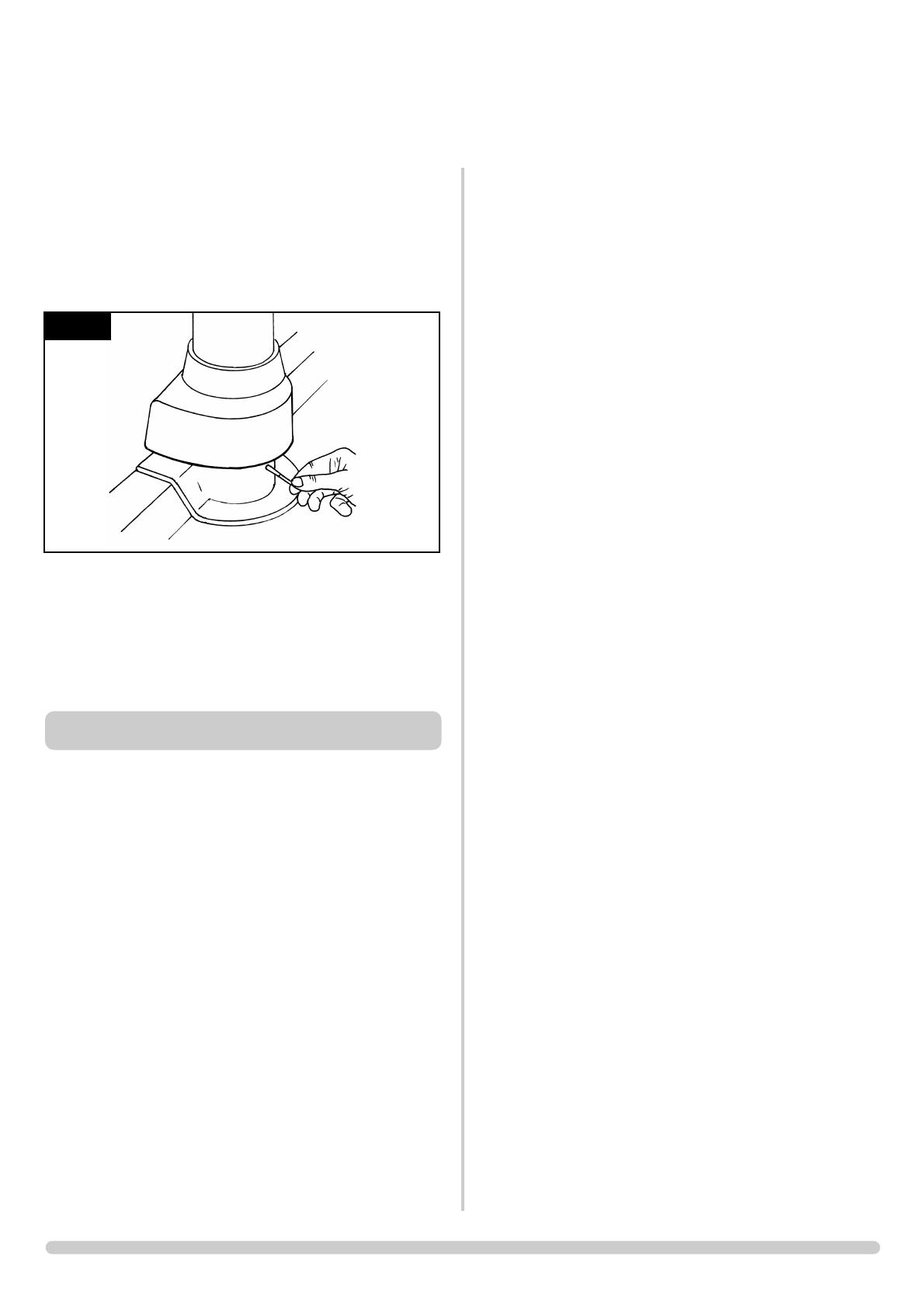
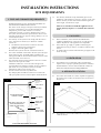
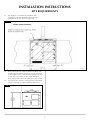
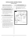
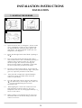
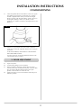
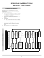
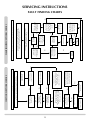
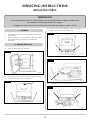
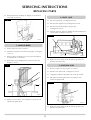
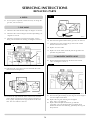
AGA Redfyre Classic Range Gas tech manual provides assistance for installing and servicing a gas range cooker. The manual includes instructions on how to connect the appliance, light the burner, and commission the appliance. It also includes troubleshooting charts, a list of replacement parts, and a service record.
This manual is essential for anyone who wants to install or service an AGA Redfyre Classic Range Gas cooker. It provides clear and concise instructions that will help you complete the task safely and efficiently.
Some of the key features of the AGA Redfyre Classic Range Gas cooker include:


-
 1
1
-
 2
2
-
 3
3
-
 4
4
-
 5
5
-
 6
6
-
 7
7
-
 8
8
-
 9
9
-
 10
10
-
 11
11
-
 12
12
-
 13
13
-
 14
14
-
 15
15
-
 16
16
-
 17
17
-
 18
18
-
 19
19
-
 20
20


Redfyre Redfyre Classic Range Gas tech manual Owner's manual
- Category
- Fireplaces
- Type
- Owner's manual
- This manual is also suitable for
AGA Redfyre Classic Range Gas tech manual provides assistance for installing and servicing a gas range cooker. The manual includes instructions on how to connect the appliance, light the burner, and commission the appliance. It also includes troubleshooting charts, a list of replacement parts, and a service record.
This manual is essential for anyone who wants to install or service an AGA Redfyre Classic Range Gas cooker. It provides clear and concise instructions that will help you complete the task safely and efficiently.
Some of the key features of the AGA Redfyre Classic Range Gas cooker include:
Ask a question and I''ll find the answer in the document
Finding information in a document is now easier with AI
Related papers
-
AGA CR9215 Owner's manual
-
-
-
-
-
-
-
Other documents
-
Stovax 8050 User manual
-
-
-
-
-
-
-
-
-