Crestron DM-MD32X32 User guide
- Category
- Blu-Ray players
- Type
- User guide
This manual is also suitable for

DO GUIDE
DO Check the Box
QUANTITY PRODUCT COLOR PART NUMBER
1 Cable, USB 2.0, A - B, 6’ (1.83 m) 2014966
8, 16, or 32 Connector, 4-Pin 2003576
4 Foot, 0.5" x 0.5" x 0.23", Adhesive Black 2002389
DM-MD8X8 and DM-MD8X8-RPS Only
1 Power Cord, 6' 7" (2 m) 4505164
DM-MD16X16, DM-MD16X16-RPS, DM-MD32X32, and DM-MD32X32-RPS Only
1 Power Cord, 6' 6" (2 m) 4510874
DM-MD8X8, DM-MD16X16, and DM-MD32X32 Only
8, 16, or 32 Connector, 3-Pin with Jumpers 4508102
DM-MD8X8-RPS, DM-MD16X16-RPS, and DM-MD32X32-RPS Only
8, 16, or 32 Connector, 3-Pin 2003575
DM-MD8X8 and DM-MD8X8-RPS Only
2 Bracket, Rack Ear, 4U 2029093
DM-MD16X16 and DM-MD16X16-RPS Only
2 Bracket, Rack Ear, 7U 2023207
DM-MD8X8, DM-MD8X8-RPS, DM-MD16X16, and DM-MD16X16-RPS Only
6 or 14 Screw, 6-32 x 3/8", Undercut Head, Phillips Black 2007235
DM-MD8X8/DM-MD16X16/DM-MD32X32/DM-MD8X8-RPS/DM-MD16X16-RPS/
DM-MD32X32-RPS
DigitalMedia™ Switchers
DO Install the Device
Crestron
®
DigitalMedia™ switchers can be mounted into a rack or can be
placed onto a at surface.
NOTE: Unless otherwise indicated, references to the DM-MD8X8,
DM-MD16X16, and DM-MD32X32 throughout this guide also apply to
the DM-MD8X8-RPS, DM-MD16X16-RPS, and DM-MD32X32-RPS,
respectively.
Mounting into a Rack
For information about mounting the DM-MD8X8 or DM-MD16X16 into a
rack, refer to the “Mounting the DM-MD8X8 or DM-MD16X16 into a Rack”
section. For information about mounting the DM-MD32X32 into a rack,
refer to the “Mounting the DM-MD32X32 into a Rack” section.
Mounting the DM-MD8X8 or DM-MD16X16 into a Rack
The DM-MD8X8 occupies 4U of rack space. The DM-MD16X16 occupies
7U of rack space. Using a #2 Phillips screwdriver (not included) and
the included 6-32 x 3/8" Phillips head screws, attach the two included
rack ears to the device. Then, mount the device into the rack using four
mounting screws (not included) for the DM-MD8X8 and eight mounting
screws (not included) for the DM-MD16X16.
Attachment of Rack Ears (DM-MD8X8 Shown)
Mounting the DM-MD32X32 into a Rack
The DM-MD32X32 occupies 14U of rack space. Rack ears are molded
into the chassis and cannot be removed. Mount the device into the rack
using eight mounting screws (not included).
Placing onto a Flat Surface
When placing the device onto a at surface or stacking it with other
equipment, attach the included feet near the corner edges on the
underside of the device.
DO Connect Input and Output Cards
Various input and output cards are available for the DigitalMedia
switchers.
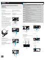
Connecting Input Cards
The following illustrations provide information about connections to some
of the available input cards.
DMC-4K-C-DSP Input Card
DMC-4K-HD-DSP Input Card
DMC-S-DSP Input Card
DMC-SDI Input Card
DMC-STR Input Card
Connecting Output Cards
The following illustrations provide information about connections to some
of the available output cards.
DMC-4K-CO-HD Output Card
DMC-4K-HDO Output Card
DMC-SO-HD Output Card
DMC-STRO Output Card
HDMI
®
Digital Video/
Audio Output
From DM
®
Transmitter or
Other DM Device or from
HDBaseT
®
Device
Unbalanced Stereo
Line Level
Audio Output
From PoDM Power Supply or
from 802.3af or 802.3at
Compliant PoE PSE
Unbalanced Stereo
Line Level
Audio Output
From USB Host
Interface of USB
HID Compliant Host
Device
HDMI
Digital Video/
Audio Output
HDMI
Digital Video/
Audio Input
HDMI
Digital Video/
Audio Output
From DM 8G
®
Fiber
Output of DM Transmiter
or Other DM Device
Unbalanced Stereo
Line Level
Audio Output
HDMI
Digital Video/
Audio Output
Unbalanced Stereo
Line Level
Audio Output
SDI
Video Input
SDI
Video/Audio
Loop-Through
Output
Unbalanced Stereo
Line Level
Audio Output
10BASE-T/100BASE-TX/
1000BASE-T Ethernet
(For Streaming Only)
HDMI
Digital Video/
Audio Output
To DM Receiver
or Other DM Device
or to HDBaseT Device
From PoDM Power Supply or
from 802.3af or 802.3at
Compliant PoE PSE
HDMI
Digital Video/
Audio Output
To DM Receiver
or Other DM Device
or to HDBaseT Device
From PoDM Power Supply or
from 802.3af or 802.3at
Compliant PoE PSE
HDMI
Digital Video/
Audio Output
To DM 8G Fiber Input
of DM Receiver or
Other DM Device
To DM 8G Fiber Input
of DM Receiver or
Other DM Device
HDMI
Digital Video/
Audio Output
Balanced/Unbalanced
Stereo Line Level Outputs
HDMI
Digital Video/
Audio Output
10BASE-T/100BASE-TX/
1000BASE-T Ethernet
(For Streaming Only)

DO GUIDE
DOC. 7820A (2044925) 10.15
Specications subject to change without notice.
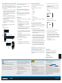
DO Power DM 8G+ Devices Using Power over DM
The DM IN port of a DM 8G+
®
input card and the DM OUT port of a DM
8G+ output card can power connected DM 8G+ devices using Power over
DM (PoDM or PoDM+). To enable the DM IN or DM OUT port to use PoDM
or PoDM+, do the following:
• For PoDM, connect the corresponding POE IN port to a PoDM power
supply (DM-PSU-8 or DM-PSU-16) or to 802.3af or 802.3at Power
over Ethernet (PoE) compliant Power Sourcing Equipment (PSE).
Refer to the connected DM 8G+ device documentation for PoDM
capabilities and requirements.
• For PoDM+, connect the corresponding POE IN port to 802.3at
Type 2 Class 4 PoE+ compliant PSE such as the CEN-SWPOE-16.
Refer to the connected DM 8G+ device documentation for PoDM+
capabilities and requirements.
NOTE: At the time of publication of this document, the
DM-RMC-4K-SCALER-C is the only DigitalMedia endpoint that
requires PoDM+.
Refer to the following illustration for an example of powering DM 8G+
devices using PoDM.
Powering DM 8G+ Devices Using PoDM
NOTE: The POE IN port does not provide a network connection. The POE
IN port is used to enable PoDM or PoDM+ only.
NOTE: The internal power supply of a DigitalMedia switcher does not
power DM 8G+ devices.
NOTE: When PoDM or PoDM+ is used to power a DM 8G+ device,
connection of the DM 8G+ device to the included power pack is not
required.
NOTE: Any wiring that is connected to a PoDM or PoE PSE port is for
intrabuilding use only and should not be connected to a line that runs
outside of the building in which the PSE is located.
DO Route Inputs
Using the front panel controls, route inputs to one or more of the available
outputs as follows:
1. Press the ROUTE button. The AUDIO, VIDEO, and USB LEDs
light, indicating the signal types that are to be routed. (Pressing
the AUDIO, VIDEO, and USB buttons selects or deselects the
corresponding signal type.)
2. Press the appropriate IN button that corresponds to the input to be
routed. The LED of the selected input lights, and the LEDs of any
outputs to which the input is currently routed also light.
3. Press the appropriate OUT buttons that correspond to the desired
outputs. The LEDs of the selected outputs ash to indicate that the
input is not yet routed.
4. Press the ENTER button to route the input. The LEDs of the selected
outputs light steadily, and the display shows the input number and
the outputs to which the input is routed.
To disconnect an input from an output, do the following:
1. Press the ROUTE button.
2. Press the desired OUT button. The display shows IN None.
3. Press the ENTER button. The output is disconnected from the input.
DO Congure the DM Switcher
Congure input, output, and network settings using the front panel
controls and Installer Tools.
Conguration of network settings includes the following:
• IP Address
• Subnet Mask
• Default Router
• DHCP
• Hostname
• Control System IP Address
• Private Network Mode (refer to the following section for additional
information)
DO Congure Private Network Mode
Congure Private Network Mode (PNM) as necessary. PNM allows a DM
system to consume only one IP address in the public network. PNM is
enabled by default.
When PNM is enabled, be aware of the following:
• In a DM system containing a single DM switcher, the DM switcher
is the only DM device that consumes an IP address. When DHCP is
enabled, the IP address is set dynamically. When DHCP is disabled,
the IP address is set manually.
• All DM I/O cards and DM endpoints (transmitters and receivers)
that are connected to the DM switcher are hidden from the public
network and cannot be reached directly; instead, all communication
is managed through the DM switcher. As a result, PNM creates a
completely private IP network for all DM cards and endpoints.
NOTE: When connected to a DM switcher, a DM endpoint must not
have its convenience Ethernet port connected to the LAN.
A DM endpoint receives its network connection via the DM switcher.
The convenience Ethernet port of a DM endpoint is available for
connection to a network device such as a PC, Blu-ray™ player,
or T V.
When multiple DM switchers are cascaded, assign a unique system ID to
each switcher. PNM uses the system ID of each switcher to determine the
internal IP address used by each device in the DM system.
NOTE: When PNM is enabled, each DM switcher must connect directly
to the LAN. A DM switcher cannot connect to the LAN through another
DM switcher.
To assign a unique system ID to a DM switcher, do the following:
1. In the Network section of Installer Tools, navigate to the Private
Network Mode conguration screen.
NOTE: Private Network Mode is enabled by default (State is set
to On).
2. Select System ID.
The Edit System ID conguration screen appears.
The system ID ranges from 1 to 64. The default system ID is 1.
3. Select a unique system ID for the DM switcher.
NOTE: Ensure that a unique system ID is set for the DM
switcher when connected to other DM switchers. In addition, it is
recommended that the default system ID not be used when multiple
DM switchers are installed in a facility. The use of a system ID other
than the default system ID avoids potential conicts when bringing
additional switchers online.
4. Press the MENU button to exit Installer Tools.
As of the date of manufacture, the product has been tested and found to comply with
specications for CE marking.
This product is Listed to applicable UL Standards and requirements by Underwriters
Laboratories Inc.
Federal Communications Commission (FCC) Compliance Statement
This device complies with part 15 of the FCC Rules. Operation is subject to the following two
conditions:
(1) This device may not cause harmful interference, and (2) this device must accept any interference
received, including interference that may cause undesired operation.
CAUTION: Changes or modications not expressly approved by the manufacturer responsible for
compliance could void the user’s authority to operate the equipment.
NOTE: This equipment has been tested and found to comply with the limits for a Class B digital
device, pursuant to part 15 of the FCC Rules. These limits are designed to provide reasonable
protection against harmful interference in a residential installation. This equipment generates,
uses and can radiate radio frequency energy and, if not installed and used in accordance with
the instructions, may cause harmful interference to radio communications. However, there is no
guarantee that interference will not occur in a particular installation.
If this equipment does cause harmful interference to radio or television reception, which can
be determined by turning the equipment off and on, the user is encouraged to try to correct the
interference by one or more of the following measures:
• Reorient or relocate the receiving antenna.
• Increase the separation between the equipment and receiver.
• Connect the equipment into an outlet on a circuit different from that to which the receiver is
connected.
• Consult the dealer or an experienced radio/TV technician for help.
Industry Canada (IC) Compliance Statement
CAN ICES-3(B)/NMB-3(B)
The DMC Fiber Series are class 1 laser products. They comply with safety
regulations of IEC-60825-1, FDA 21 CFR 1040 11 and FDA 21 CFR 1040 10.
WARNING: Visible and invisible laser radiation when open. Avoid direct exposure to beam.
NOTE: Plug the included dust cap into the optical transceiver when the ber optic cable is
unplugged.
Rack Mounting Safety Precautions
• Elevated Operating Ambient Temperature: If installed in a closed or multi-unit rack assembly, the operating
ambient temperature of the rack environment may be greater than room ambient temperature. Therefore,
consideration should be given to installing the equipment in an environment compatible with the maximum
ambient temperature (Tma) specied by the manufacturer.
• Reduced Airow: Installation of the equipment in a rack should be such that the amount of airow required for
safe operation of the equipment is not compromised.
• Mechanical Loading: Mounting of the equipment in the rack should be such that a hazardous condition is not
achieved due to uneven mechanical loading.
• Circuit Overloading: Consideration should be given to the connection of the equipment to the supply circuit and
the effect that overloading of the circuits might have on overcurrent protection and supply wiring. Appropriate
consideration of equipment nameplate ratings should be used when addressing this concern.
• Reliable Earthing: Reliable earthing of rack-mounted equipment should be maintained. Particular attention should
be given to supply connections other than direct connections to the branch circuit (e.g., use of power strips).
Electrical Connection
“This product must be connected to an earthed mains socket-outlet.”
• Finland: “Laite on liitettävä suojamaadoituskoskettimilla varustettuun pistorasiaan.”
• Norway: “Apparatet må tilkoples jordet stikkontakt.”
• Sweden: “Apparaten skall anslutas till jordat uttag.”
The specic patents that cover Crestron products are listed at http://www.crestron.com/legal/patents.
The product warranty can be found at www.crestron.com/warranty.
Certain Crestron products contain open source software. For specic information, please visit www.crestron.com/opensource.
Manufactured under license under U.S. Patent Nos.: 5,956,674; 5,974,380; 6,226,616; 6,487,535; 7,212,872; 7,333,929; 7,392,195; 7,272,567
& other U.S. and worldwide patents issued & pending. DTS-HD, the Symbol, & DTS-HD and the Symbol together are registered trademarks of DTS,
Inc. Product includes software. © DTS, Inc. All Rights Reserved.
Manufactured under license from Dolby Laboratories. Dolby and the double-D symbol are trademarks of Dolby Laboratories.
Crestron, the Crestron logo, DigitalMedia, DM, DM 8G, and DM 8G+ are either trademarks or registered trademarks of Crestron Electronics, Inc.,
in the United States and/or other countries. Blu-ray is either a trademark or registered trademark of the Blu-ray Disc Association in the United
States and/or other countries. HDBaseT and the HDBaseT Alliance logo are either trademarks or registered trademarks of the HDBaseT Alliance
in the United States and/or other countries. HDMI and the HDMI logo are either trademarks or registered trademarks of HDMI Licensing LLC in
the United States and/or other countries. Other trademarks, registered trademarks, and trade names may be used in this document to refer to
either the entities claiming the marks and names or their products. Crestron disclaims any proprietary interest in the marks and names of others.
Crestron is not responsible for errors in typography or photography.
This document was written by the Technical Publications department at Crestron.
©2015 Crestron Electronics, Inc.
DO Learn More
Visit the website for additional information and the latest
rmware updates. To learn more about this product, use
a QR reader application on your mobile device to scan
the QR image.
Crestron Electronics
15 Volvo Drive, Rockleigh, NJ 07647
888.CRESTRON | www.crestron.com
Private Network Mode
State: On
System ID: 1
Edit System ID
1
DM-PSU-8, Rear Panel
DM OUT
DM-TX1-4K-C-1G,
Rear Panel
Main Power Input
Ground
DMC-4K-C-DSP
DM 8G+
PoDM
DM 8G+
PoDM
DMC-4K-CO-HD
DM-RX1-4K-C-1G,
Rear Panel
-
 1
1
-
 2
2


Crestron DM-MD32X32 User guide
- Category
- Blu-Ray players
- Type
- User guide
- This manual is also suitable for
Ask a question and I''ll find the answer in the document
Finding information in a document is now easier with AI
Related papers
-
Crestron DM-PSU-8 User guide
-
-
-
-
-
-
-
-
-