Page is loading ...

GAS FIRED HIGH EFFICIENCY FURNACE
DOWN FLOW & DIRECT VENT (SEALED COMBUSTION)
MODEL: CMA1-50N & CMA2-75N
INSTALLATION AND SERVICE MANUAL
For installation in:
1. Manufactured Homes
2. Modular Homes/Buildings
3. Site Constructed—Residential (Single Story Dwellings)
FOR YOUR SAFETY
Do not store or use gasoline or other flammable vapors and liquids in the vicinity of this
or any other appliance.
WHAT TO DO IF YOU SMELL GAS
• Do not try to light any appliance.
• Do not touch any electrical switch; do not use any phone in your building.
• Immediately call your gas supplier from a neighbor’s phone.
Follow the gas supplier’s instructions.
• If you cannot reach your gas supplier, call the fire department.
: If the information in these instructions is not followed exactly, a fire or explosion may
result causing property damage, personal injury, or loss of life.
: Improper installation, adjustment, alteration, service, or maintenance can cause
injury or property damage. Refer to this manual. For assistance or additional information,
consult a qualified installer, service agency, or fuel supplier.
: Do not use this appliance if any part has been underwater. Immediately call a
qualified service technician to inspect the appliance and to replace any part of the electrical or
control system that has been underwater.
THERMO PRODUCTS, LLC.
POST OFFICE BOX 217
NORTH JUDSON, IN 46366
PHONE: (574) 896-2133
MG-508
ECN 5135-MA 100615
MADE IN USA
PLEASE READ THESE INSTRUCTIONS PRIOR TO INSTALLATION, INITIAL FIRING, AND BEFORE
PERFORMING ANY SERVICE OR MAINTENANCE. THESE INSTRUCTIONS MUST BE LEFT WITH THE USER
AND SHOULD BE RETAINED FOR FUTURE REFERENCE BY QUALIFIED SERVICE PERSONNEL.

TABLE OF CONTENTS
SECTION BEGINNING PAGE
I. SAFETY INFORMATION 1
II. FURNACE SPECIFICATIONS 6
III. GENERAL INSTRUCTIONS AND CLEARANCES 7
IV. GENERAL INSTALLATION 9
A. FURNACE LOCATION 9
B. BASE INSTALLATION 12
C. ALCOVE INSTALLATION 13
D. CLOSET INSTALLATION 14
E. FUEL PIPING 15
F. GENERAL VENTING REQUIREMENTS 16
G. CONNECTING THE EXHAUST VENT, AND COMBUSTION 18
AIR INTAKE
H. DIRECT VENTING THROUGH A SIDEWALL 19
I. INSTALLATION OF OUTSIDE EXHAUST/INTAKE TERMINATIONS 23
J. CONNECTING THE FURNACE TO ROOF VENT/ INTAKE TERMINATIONS 24
K. CONDENSATE DRAIN LINE AND TRAP ASSEMBLY 26
L. ELECTRICAL WIRING 27
V. STARTING THE UNIT 32
A. SEQUENCE OF OPERATION 32
B. INITIAL START-UP 34
C. ADJUSTMENT OF BTU INPUT RATE 35
D. BURNER ADJUSTMENT 36
E. SETTING TEMPERATURE RISE 37
F. FURNACE CHECK-OUT PROCEDURE 38
VI. INSTALLER'S INSTRUCTIONS TO USER 39
VII. DEALER MAINTENANCE 39
A. ELECTRICAL 40
B. GENERAL INSPECTION 40
C. HEAT EXCHANGER 41
D. HOUSE AIR BLOWER 41
E. RETURN AIR FILTER 41
VIII. TROUBLE SHOOTING 42
APPENDIX-A REPLACEMENT PARTS 49
APPENDIX-B WIRING DIAGRAM 51
WARRANTY 52
REFERENCED PUBLICATIONS: FOR COPIES CONTACT:
NATIONAL FUEL GAS CODE NATIONAL FIRE PROTECTION ASSOCIATION
NFPA 54/ANSI-Z233.1 1 BATTERYMARCH PARK
(LATEST EDITION) P.O. BOX 9101
QUINCY, MA 02269-9101

All installations and services must be performed by qualified service personnel.
I. SAFETY INFORMATION
This and the following page contain reproductions of the various warning and instruction
labels placed on the Thermo Pride Condensing Gas Furnaces. Please read and comply
with the contents of these labels.
1

All installations and services must be performed by qualified service personnel.
This and the previous page contain reproductions of the various safety and instruction
labels placed on the Thermo Pride Condensing Gas Furnaces. Please read and comply
with the contents of these labels.
2

All installations and services must be performed by qualified service personnel.
The following safety information should be read, understood, and followed by the
installer.
1. Use only with type of gas approved for this furnace. Refer to furnace rating plate.
2. Do not install this furnace where it could be exposed to drafts or other wind or
moisture conditions. Refer to Section IV of this manual.
3. Provide adequate ventilation air to the furnace space. Refer to Section IV, C and D,
of this manual.
4. Connect this furnace to an approved vent system only. Combustion products must
be carried outdoors. Refer to Section IV, F thru J, of this manual.
5. Never test for gas leaks with an open flame. Leak test methods must comply with
State, Local and National codes including the National Fuel Gas Code NFPA 54/ANSI-
Z233.1 (Latest Edition).
6. Always install furnace with a duct system that has an external static pressure within
the allowable range referenced in specifications.
7. Make sure supply air ducts are completely sealed to the furnace casing. Refer to
Section IV.
The following pages contain various warnings and cautions found throughout the
Thermo Pride Gas Fired High Efficiency Furnace Manual. Please read and comply
with the statements below.
: This furnace is not to be used for temporary heating of buildings or
structures under construction.
: These high efficiency condensing furnaces are not certified for and
shall not be vented into a standard or any type of chimney.
: Negative pressure inside the closet with closet door closed and the
furnace blower operating on high speed shall be no more negative than minus
0.05 inch water column.
: Do not obstruct any return air openings, including the return grille on
the furnace. To do so may cause the furnace to activate the high limit and shut
down.
3

All installations and services must be performed by qualified service personnel.
: The vent and air intake elbows must be kept away from bushes,
shrubs or any vegetation that may restrict the flow of flue products. It must also
be kept clear of any leaves, weeds or other combustible materials. Keep the vent
hood clear of snow. Avoid locating the terminals in areas where standing water or
condensate drippage may be a problem.
: This CMA furnace has been designed to be installed as a direct vent
system and must have its combustion air brought in from outside the conditioned
space. The failure to install the vent/air intake system as specified in these
instructions will void the heat exchanger warranty and may result in property
damage, personal injury or loss of life.
: Outside combustion air must not come from an area that is directly
adjacent to a pool, hot tub or spa. Measures should be taken to prevent the entry
of corrosive chemicals or vapors to the combustion and ventilation air supply.
Such chemicals include but are not limited to chlorinated and/or fluorinated
hydrocarbons such as found in refrigerants, aerosol propellants, dry cleaning
fluids, degreasers and removers. Other harmful compounds may come from
bleaches, air fresheners or mastics. Vapors from such products can form acid
compounds when burned in a gas flame. Should acid compounds form in your
furnace, it may reduce the life of the furnace.
: Because of the potential of odorant fade, a gas leak may not be
detected by smell. If this furnace is installed below grade, contact your gas
supplier for a gas detector.
: All gas piping must be leak tested methods approved by State, Local
and National Codes including the National Fuel Gas Code NFPA 54/ANSI-Z233.1
(Latest Edition). A final test for gas leakage must be made after purging the gas
line. This test must be conducted with the unit operating and should include the
furnace piping and gas valve. Never use an open flame to check for a gas leak.
: Care must be taken not to wet electronic components during leak test.
Wetting the primary ignition module may damage its circuitry and cause a
hazardous situation. Dry moisture from all leads and terminals if wetting occurs.
Wait at least 24 hours for the circuit to fully dry before energizing the burner
circuit.
: The furnace and its individual gas shutoff valve must be disconnected
from the gas supply during pressure testing of the gas supply system at
pressures in excess of 1/2 PSIG or 14.0" w.c. The furnace must be isolated from
the gas supply by closing its manual shut off valve at test pressures equal to or
greater than 1/2 PSIG or 14.0" w.c.
4

All installations and services must be performed by qualified service personnel.
: Copper and brass tubing and fittings (except tin lined) shall not be
used if the gas contains more than a trace (0.3 grains per 100 cubic ft.) of
hydrogen sulfide gas. Check with your gas supplier.
: TURN OFF THE ELECTRICAL POWER to the furnace before attempting
to change blower speed wiring.
: Turn off power to furnace before it is placed into service. The gas
piping system must have been leak tested by a qualified heating contractor in
accordance with State, Local and National Codes including the National Fuel Gas
Code NFPA 54/ANSI-Z233.1 (Latest Edition).
: It may be necessary to purge the air out of the gas line for initial start-
up of the furnace after installation. This should be done by a qualified heating
contractor. If excessive gas escapes when purging the gas supply at the union,
allow the area to ventilate for at least 15 minutes before attempting to start the
furnace. LP gas is especially dangerous because the specific gravity of LP gas
allows it to accumulate at floor level at a dangerous concentration.
: Heat exchanger oil will burn off on initial firing creating an unpleasant
odor. To prevent this odor from occurring more than once, it is suggested that:
1. A window(s) be opened.
2. The thermostat set at highest setting.
3. The furnace remain running at conditions 1&2 above for 15 minutes or until
odor has dissipated.
: The CMA furnace models are of direct vent design and do not require
an air shutter adjustment (air shutters are not used) for proper flame
characteristics. Burner box access cover must always be secured with all screws
in place and tightened before operating furnace.
: Personal injury or property damage could result from repair or service
of this furnace by anyone other than a qualified heating contractor.
: Label wires prior to disconnection when servicing controls. Wiring
errors can cause improper and dangerous operation.
: The inducer motor mounting plate gasket and the collector box gasket
must be replaced if they show any sign of having been damaged.
: Power must be disconnected before servicing.
5

All installations and services must be performed by qualified service personnel.
II. FURNACE SPECIFICATIONS - CMA SERIES
MODEL CMA1-50 CMA2-75
INPUT IN BTUH 50,000 75,000
OUTPUT IN BTUH 48,000 72,000
MAIN ORIFICE-NAT.
MAIN ORIFICE-LP
GAS SUPPLY PRESSURE
L.P. MINIMUM
NAT. MINIMUM
L.P. MAXIMUM
NAT. MAXIMUM
GAS MANIFOLD PRESSURE
L.P.
NAT.
INTAKE SIZE IN INCHES
VENT SIZE IN INCHES
NOMINAL TEMPERATURE RISE
SEASONAL EFFICIENCY (AFUE*)
*ANNUAL FUEL UTILIZATION EFFICIENCY
DIMENSIONS
CABINET SIZE
SUPPLY AIR OUTLET
ELECTRICAL SUPPLY
FUSE OR HACR BREAKER
TOTAL CURRENT AMPS
NOMINAL ANTICIPATOR SETTING
FILTER SIZE
APPROXIMATE SHIPPING WEIGHT
BLOWER DATA
BLOWER MODEL
MOTOR HORSEPOWER
MOTOR RPM
CFM @ .2 & .5 IN. W.C. SPEED .2”
.5” |.2” .5”
LOW 805 695 | 797 668
MD-LOW 1010 860 | 995 869
MD-HIGH 1196 1038 | 1210 1076
HIGH 1338 1162 | 1420 1259
FOR BURNER COMBUSTION INFORMATION REFER TO INITIAL STARTUP.
2”
2”
11” IN.W.C.
4.5”IN.W.C.
14” IN.W.C.
14” IN.W.C.
#42
1.5 mm
115 VOLTS-- 60HZ --1/PH
15 AMPS
55°F
95%
WIDTH 18” DEPTH 25-3/4" HEIGHT 57"
WIDTH 12” DEPTH 12"
10.0” +
.03 IN.W.C.
3.5” +
.03 IN. W.C.
12-9T DIRECT DRIVE
1/2
1065 (HIGH SPEED)
7.15 AMPS
0.8 MILLIAMPS
(1) 18” X 24” X 1”
175 LBS.
6

All installations and services must be performed by qualified service personnel.
INSTALLATION PARTS PACKAGE
CMA*-50 CMA*-75
S00S4179 S00S4114
PART # QTY PART # QTY
J-box cover 350020 1 350020 1
wire nut 300132 2 300132 2
3" stainless steel hose clamp 300276 4 300276 4
2-3/8" radiator hose 410017 2 410017 2
CPVC adapter 320833 1 320833 1
LP conversion kit AOPS7677 1 AOPS7678 1
PARTS PKG#
DESCRIPTION
III. GENERAL INSTRUCTIONS AND CLEARANCES – READ BEFORE START OF
INSTALLATION
1. The BTU output capacity of the furnace proposed for installation should be based
on a heat loss calculation made according to the manuals provided by the Air
Conditioning Contractors of America (ACCA) or the American Society of Heating,
Refrigeration and Air Conditioning Engineers, Inc. (ASHRAE).
2. This furnace is equipped with orifices sized for operation with natural gas. For
conversion to Propane Gas see instruction MG-799 in Gas Conversion Kit
AOPS7678.
3. These Category Type IV furnaces are shipped completely assembled and wired
(internally). See the Dealer Receiving and Freight Claim Procedure Section of the
price guide for parts shortage or damage. The furnace and duct system must be
adjusted to obtain a temperature rise of 40°F to 70°F through the furnace after
installation. (See rating label located on separator panel inside the furnace
vestibule). The installation must conform with local codes, or in the absence of local
codes, with the National Fuel Gas Codes (ANSI Z223.1 or latest edition) and with
these instructions.
: This furnace is not to be used for temporary heating of buildings or
structures under construction.
Many of the chemicals used during construction, when burned, form acid bearing
condensate that can substantially reduce the life of the heat exchanger.
4. It is recommended that a commercially available CO alarm be installed in
conjunction with any fossil fuel burning appliance. The CO alarm shall be installed
according to the alarm manufacturer’s installation instructions and be listed in
7

All installations and services must be performed by qualified service personnel.
accordance with the latest edition of the UL Standard for Single and Multiple Station
Carbon Monoxide Alarms, UL 2034, or the CSA International Standard, Residential
Carbon Monoxide Alarming Devises, CSA 6.19.
5. The installer shall be familiar with and comply with all codes and regulations
applicable to the installation of these heating appliances and related equipment. In
lieu of local codes, the installation shall be in accordance with the current provisions
of one or more of the following standards.
a. Federal Manufactured Home Constructions & Safety Standard (H.U.D. Total
24, Part 280.)
b. American National Standard (ANSI-119.2/NFPA-501C) for all recreational
vehicle installations.
c. American National Standard (ANSI-Z223.1/NFPA-54) for all gas-fired
furnaces.
d. American National Standard (ANSI-C1/NFPA-70 Electric Code for all
electrical field wiring.
e. These gas-fired units have been investigated under standards ANSI Z 21.47
CAN/CGA Z223-2001 Central Furnace test standards.
f. These gas-fired units have been listed by ETL “For installation as central
furnace special type for single story dwelling.”
: The area around the furnace must be kept free and clear of
combustible materials, especially papers and rags.
: This furnace is not to be used as a construction heater.
Listed below are definitions of “ COMBUSTIBLE MATERIAL” and “NON-
COMBUSTIBLE MATERIAL.”
COMBUSTIBLE MATERIAL:
Material made of or surfaced with wood, compressed paper, plant fibers, plastics or
other material that will ignite.
NON-COMBUSTIBLE MATERIAL:
Material that will not ignite and burn. Such materials consist entirely of steel, iron, brick,
tile, concrete, slate, glass or a plaster combination thereof.
8

All installations and services must be performed by qualified service personnel.
MODELS CMA
CLOSET ALCOVE
FRONT
BACK
SIDES
VENT CONNECTOR(PVC)
TOP
PLENUM SIDES
TOP AND SIDES OF DUCT
BOTTOM OF DUCT
6”
0”
0”
0”
0”
1”
1”
1”
18”
0”
0”
0”
0”
1”
1”
1”
Table 1
This heating appliance must be installed with clearances not less than the minimums
shown above as well as ample clearance for easy access to the air filter, blower
assembly, burner assembly, controls, and vent connections.
IV. GENERAL INSTALLATION
A. FURNACE LOCATION
1. For best performance, locate the furnace so that it is centralized with respect
to the duct system.
2. The furnace installation is only intended for free air return through the furnace
door louvers. DO NOT connect a ducted return air system directly to the furnace.
An improper return air installation may create a hazard and damage equipment,
as well as void all warranties.
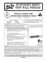
3. This furnace may be installed on a combustible floor when utilizing either the
No. 70 counterflow floor base or CE111S / CE211T coil cabinet for below the
floor duct systems, or the cottage base for floor level air distribution. See Figure
1A for description of Combustible Floor Base and Figure 1C for Cottage Base.
This furnace is ETL listed for closet, alcove or free standing applications. All
applications must comply with the requirements of this manual.
9

All installations and services must be performed by qualified service personnel.
Combustible Floor Base
Model: 70-BASE
Figure 1A.
Coil Cabinet
Model: CE113S Note: This cabinet cannot be utilized as a cottage base.
Figure 1B.
10

All installations and services must be performed by qualified service personnel.
Cottage Base
Model: 01COT-BASE
Figure 1C.
NOTE: Serves as a plenum for single story applications with exposed supply air
systems.
11

All installations and services must be performed by qualified service personnel.
B. BASE INSTALLATION
1. Combustible Floor Base Model: 70 BASE
Use the base bottom panel as a template to mark floor opening locations (see
Figure 2). Cut a square opening in the floor for the supply air connector duct. Cut
the opening 1-inch larger than the square template opening. (duct requires 1-inch
clearance to combustible floor).
Figure 2.
Figure 3.
After cutting openings in the floor, place the bottom panel in position. Mark the
square opening location on the distribution duct at the connection point of the
12

All installations and services must be performed by qualified service personnel.
connector duct. Remove the bottom panel. Cut an opening in the distribution duct
slightly larger than the connector duct. (refer to Figure 2 for location of this cut.)
Cut the connector duct to length. Install the connector duct. Bend over each tab.
Insure an airtight seal by using high temperature sealant or tape on the joint.
Reinstall the bottom panel over the connector duct. Put the base top assembly in
place (see Figure-3).
Slit the corners of connector duct down to the top of the base assembly. If metal
projects more than 1-inch above the top of the base assembly, trim the flanges
down to 1-inch. While the top of distribution duct is being pulled up with one
hand, bend down each side of the connector duct tightly to the base assembly
with the other hand. This assures a tight connection between the base assembly
and the connector duct and that the distribution duct will be full size. Use high
temperature tape and/or high temperature silicone caulking on all joints and
seams to minimize air leakage. Secure the base assembly to the floor with two
screws in the front flange.
2. Cottage Base Model: 01COT BASE
The 01COT BASE cottage base (Figure 1C) is required for a freestanding
cottage base installation. The cottage base allows the two sides and rear to have
an 8” x 12” register installed. IMPORTANT: All joints and seams of supply
ducts must be sealed with a sealing method suitable to the application
conditions and temperatures (I.E. High temperature silicone and/or
aluminum tape). Refer to assembly and installation instructions included with
cottage base for additional information.
C. ALCOVE INSTALLATION
In this application, a minimum of 18 inches of clearance
must
be provided to the front of the unit. See Figure 4.
Note – access to diagnostic view port.
Figure 4.
13

All installations and services must be performed by qualified service personnel.
D. CLOSET INSTALLATION
1. The return air opening into the closet
is to have a minimum free area of 250
sq. in. (see Figure 5).
2. The return air opening may be
located in the top, center or (ideally) bottom
of the closet door or side wall.
Figure 5.
: Do not obstruct any return air openings, including the return
grille on the furnace. To do so may cause the furnace to activate the high
limit and shut down.
3. The cross-sectional area of the return system leading into the closet (when
located in the floor or ceiling) shall not be less than 250 square inches.
4. The total free area of openings in the floor or ceiling registers serving the
return duct system must be at least 350 square inches. At least one register must
be located where it is not likely to be covered by carpeting, boxes, furniture or
other objects.
5. Materials located in the return duct system must have a flame spread
classification of 200 or less.
6. Non-combustible pans having one inch upturned flanges are to be located
beneath openings in a floor return duct system.
7. Wiring materials located in the return duct system must conform to articles
300-22 of the National Electrical Code NFPA70 (Latest Edition).
8. Gas piping is not to be located in or through the return duct system .
14

All installations and services must be performed by qualified service personnel.
E. FUEL PIPING
Sizing and installation of fuel lines must be in accordance with Federal, State &
Local regulations. Including the National Fuel Gas Code NFPA 54/ANSI-Z233.1
(Latest Edition).
NOTE: These furnaces are designed to be gas piped through the left side or the
bottom. For service purposes, it is recommended that the gas union be located
inside the furnace when possible.
: Because of the potential of odorant fade, a gas leak may not be
detected by smell. If this furnace is installed below grade, contact your gas
supplier for a gas detector.
A qualified installer or service person must perform all gas piping and testing.
Piping from the natural gas meter to the furnace shall be in accordance with
requirements of the local gas utility. Piping from the LP tank to the furnace must
follow the recommendations of the gas supplier.
A readily accessible manual shut off valve (certified for the applicable gas) with a
non-displaceable rotor member shall be installed within six feet of the gas
equipment it serves.
A union or flanged connection shall be provided directly up stream of the burner
to allow burner removal. Unions must be of a ground joint type or flange-jointed
type using a gasket resistant to the applicable gas. Pipe dope or sealant certified
to be resistant to the action of the applicable gases should be used on all
threaded joints.
A drip leg must be used on both LP and Natural gas installations prior to the
furnace in order to trap oil, condensate and other impurities which might
otherwise lodge in the gas valve or plug the burner orifice.
A drip leg shall be provided at the outlet of the gas meter when there is excessive
condensation between the gas meter and the furnace. Failure to install a drip leg
may void the limited warranty on the furnace.
: All gas pipe connections must be leak tested using methods
approved by State, Local and National Fuel Gas Code NFPA 54/ANSI-Z233.1
(Latest Edition). Any leaks must be repaired immediately after turning off
the gas supply. A final test for gas leakage must be made after purging the
gas line.
: DO NOT wet electronic components during the leak test.
Wetting electronic components may damage circuitry and cause a
hazardous situation. Dry moisture from all leads and terminals if wetting
occurs. Wait at least 24 hours for the circuit to fully dry before energizing
the system.
15

All installations and services must be performed by qualified service personnel.
: The furnace and its gas valve must be disconnected from the
gas supply during pressure testing of the gas supply system at pressures
in excess of 1/2 PSIG or 14 inches w.c
F. GENERAL VENTING REQUIREMENTS
The CMA furnace venting system must be installed by a qualified service person
in accordance with local codes, the National Fuel Gas Code NFPA 54/ANSI-
Z223.1 (Latest Edition) and these instructions.
The following items and local code requirements must be followed:
1. The vent/air intake terminations outlined by Thermo Products in this
manual must be used.
2. The entire vent/air intake system must be made of PVC Schedule 40 pipe
except for the concentric vent kit. NOTE: All CMA furnaces must be installed
with outside combustion air.
3. The flue vent pipe and combustion air pipe must be at least as large as the
exhaust vent/air intake pipe specified by Thermo Products. No reduction in
size is permissible. The CMA requires 2” Schedule 40 PVC pipe.
4. This CMA furnace shall not be common vented with any other appliance
including those burning solid fuels.
5. The maximum permissible vent length of straight pipe and number of
elbows permitted for the exhaust vent and combustion air inlet is shown in
Table 2 . The elbows shown are in addition to the length of straight pipe
permitted. When counting elbows, all elbows used in the exhaust vent or
combustion air intake must be counted. This includes elbows used inside the
furnace jacket and termination elbows.
Care should be taken to plan out the vent system to be as short as possible
(but not shorter than 8 ft.) and to contain as few elbows as possible to insure
the best possible operation of the furnace.
16

All installations and services must be performed by qualified service personnel.
MAXIMUM VENT LENGTH
VENT SIZE 2 IN. PVC
FURNACE
MODEL
VENT
LENGTH
(FT.)
EXHAUST
VENT
ELBOWS
(NO.)
COMBUSTION AIR INTAKE
ELBOWS (NO.)
CMA 30 8* 7**
*Note the drain elbow supplied with CMA furnaces count as 1 elbow.
**Note the two 45° elbows supplied w/CMA furnace count as 1 elbow.
Table 2
6. A hack saw may be used to cut the PVC pipe. It must be cut smoothly at
right angles with all burrs removed. All joints must use standard PVC
Schedule 40 elbows and couplings. Joints are not to be made by gluing,
except where noted, and butting together the cut or raw edges of the vent
pipe. (The joints inside the vestibule should be sealed with a silicone caulk to
allow for maintenance.) Notice: Do not use silicone caulk to seal the PVC
sleeve or coupling to the metal air intake collar on the burner box. The
screw securing the sleeve or coupling to the collar is sufficient.
7. Use the two radiator hose clamps to connect both the exhaust vent and
combustion air vent pipes to the venting system (included in the parts
package.) This will aid in the serviceability of the vent should it need to be
removed in the future. (Refer to figure 6).
8. Vent connections shall be checked for leakage with the furnace induced
draft blower running and with the vent termination blocked. A mild soap and
water solution may be used to check for leaks.
9. Vent pipe passing through an unheated space must be insulated with 1.0”
thick foil faced fiberglass insulation or its equivalent to prevent freezing of any
condensate within the pipe.
10. Minimum clearance from the PVC pipe to combustible material is zero
inches.
IMPORTANT: The CMA furnace models are vented through the roof. For
roof venting refer to Section IV, J, of this manual.
17

All installations and services must be performed by qualified service personnel.
G. CONNECTING THE EXHAUST VENT AND COMBUSTION AIR INTAKE
Figure 6. shows the typical exhaust vent and combustion air intake connection
for CMA furnace.
Figure 6.
(CMA*-75 SHOWN)
NOTICE: The exhaust vent pipe must be supported every 4 feet. After making
sure the length of the piping is correct glue all connections in place.
: This CMA furnace has been designed to be installed as a direct
vent system and must have its combustion air brought in from outside the
conditioned space. The failure to install the vent/air intake system as
specified in these instructions will void the heat exchanger warranty and
may result in property damage, personal injury or loss of life.
18
/