
Operating Manual
Model 34700-2K/17700-2K
Recovery/Recycling/Recharging Unit

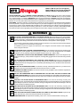
SAFETY DEFINITIONS: Follow all WARNING, CAUTION, IMPORTANT, and NOTE messages in this manual. These messages
are defined as follows: WARNING means you may risk serious personal injury or death; CAUTION means you may risk personal
injury, property damage, or unit damage; IMPORTANT means you may risk unit damage; and NOTEs provide clarity and helpful tips.
These safety messages cover situations ROBINAIR is aware of. ROBINAIR cannot know, evaluate, and advise you as to all possible
hazards. You must verify that conditions and procedures do not jeopardize your personal safety.
DISCLAIMER: Information, illustrations, and specifications contained in this manual are based on the latest information available at
the time of publication. The right is reserved to make changes at any time without obligation to notify any person or organization of
such revisions or changes. Further, ROBINAIR shall not be liable for errors contained herein or for incidental or consequential damages
(including lost profits) in connection with the furnishing, performance, or use of this material. If necessary, obtain additional health
and safety information from the appropriate government agencies and the vehicle, refrigerant, and lubricant manufacturers.
ALLOW ONLY QUALIFIED PERSONNEL TO OPERATE THE UNIT. Before operating the unit, read and follow
the instructions and warnings in this manual. The operator must be familiar with air conditioning and refrigeration
systems, refrigerants, and the dangers of pressurized components. If the operator cannot read English, operating
instructions and safety precautions must be read and discussed in the operator’s native language.
Si el operador no puede leer el inglés, las instrucciones de operación y las precauciones de seguridad deberán
leerse y comentarse en el idioma nativo del operador.
Si l’utilisateur ne peut lire l’anglais, les instructions et les consignes de sécurité doivent lui être expliquées
dans sa langue maternelle.
PRESSURIZED TANK CONTAINS LIQUID REFRIGERANT. Do not overfill the internal storage vessel because
overfilling may cause explosion and personal injury or death. Do not recover refrigerants into non-refillable
containers; use only federally authorized refillable containers (DOT spec. 4BW or 4BA).
ALL HOSES MAY CONTAIN LIQUID REFRIGERANT UNDER PRESSURE. Contact with refrigerant may
cause personal injury. Wear protective equipment, including safety goggles. Disconnect hoses using extreme
caution.
DO NOT BREATHE REFRIGERANT AND LUBRICANT VAPOR OR MIST. Exposure may cause personal
injury, especially to the eyes, nose, throat, and lungs. Use the unit in locations with mechanical ventilation that
provides at least four air changes per hour. If accidental system discharge occurs, ventilate the work area before
resuming service.
DO NOT USE AN EXTENSION CORD. An extension cord may overheat and cause fire. If you must use an
extension cord, use the shortest possible cord with a minimum size of 14 AWG.
TO REDUCE THE RISK OF FIRE, do not use the unit in the vicinity of spilled or open containers of gasoline or
other flammable substances.
DO NOT USE COMPRESSED AIR TO PRESSURE TEST OR LEAK TEST THE UNIT OR VEHICLE AIR
CONDITIONING SYSTEM. Some mixtures of air and R-134a refrigerant are combustible at elevated pressures.
These mixtures are potentially dangerous and may result in fire or explosion causing personal injury or property
damage.
USE THE 17700-2K UNIT WITH R-12 REFRIGERANT ONLY. The unit is for recovering, recycling, and
recharging only R-12 refrigerant! Do not attempt to adapt the unit for another refrigerant. Do not mix refrigerant
types through a system or in the same container; mixing of refrigerants will cause severe damage to the unit
and the vehicle air conditioning system.
USE THE 34700-2K UNIT WITH R-134a REFRIGERANT ONLY. The unit is for recovering, recycling, and
recharging only R-134a refrigerant! Do not attempt to adapt the unit for another refrigerant. Do not mix refrigerant
types through a system or in the same container; mixing of refrigerants will cause severe damage to the unit
and the vehicle air conditioning system.
HIGH VOLTAGE ELECTRICITY INSIDE THE UNIT HAS A RISK OF ELECTRICAL SHOCK. Exposure may
cause personal injury. Disconnect the power before servicing the unit.
OPERATING NOTE: At temperatures exceeding 120°F / 49°C, wait 10 minutes between recovery jobs.
WARNINGS
Model 17700-2K (for R-12 refrigerant)
Model 34700-2K (for R-134a refrigerant)
Recover, Recycle, and Recharge Unit

1
34700-2K/17700-2K Cool-Tech Recovery/Recycling/Recharging Unit
Table of Contents
Introduction .............................................................................................. 2
Glossary of Terms ................................................................................. 2
Setup Instructions.................................................................................... 2
Initial Setup ............................................................................................. 4
Vacuum Pump Initial Fill ......................................................................... 5
Installation Routine ................................................................................. 5
Operating Guidelines ............................................................................... 6
Using the Selection Menu....................................................................... 6
Change Filter .......................................................................................... 6
Recycle ................................................................................................... 7
Tank Refill............................................................................................... 7
Vacuum Oil Time .................................................................................... 7
Filter Capacity......................................................................................... 7
Basic/Advanced Prompts ....................................................................... 8
Selecting a Unit (Metric/English) ............................................................ 8
Language Select..................................................................................... 8
Change Defaults ..................................................................................... 9
Using the Control Panel.......................................................................... 9
Keypad Functions ................................................................................. 10
Operating Instructions........................................................................... 11
Operating Tips ...................................................................................... 11
Recovering Refrigerant......................................................................... 12
Evacuating the A/C System .................................................................. 14
Replenishing A/C System Oil ............................................................... 16
Recharging the A/C System ................................................................. 17
Maintenance Instructions ...................................................................... 19
Replacing the Filter-Drier...................................................................... 19
Changing the Vacuum Pump Oil .......................................................... 20
Checking for Leaks ............................................................................... 21
Electrical Protection .............................................................................. 22
General Maintenance ........................................................................... 22
Replacement Parts List ......................................................................... 22
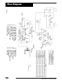
Flow Diagram.......................................................................................... 24
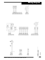
Wiring Diagram....................................................................................... 25
Limited Warranty .................................................................................... 26
U.S. Patents: 4,523,897; 4,688,388 Re 33,212; 4,768,347; 4,805,416; 4,809,520; 4,878,356; 4,938,031;
5,005,369; 5,005,375; 5,038,578; 5,042,271; 5,209,653; 5,248,125; Australian Patent: 613,058; Canadian
Patents: 1,311,621; 1,311,622; 2,012,620; 2,026,348; European Patent: 0 315 296 Bl; German Patent: 031296
Mexican Patent: 16208 OTHER U.S. AND FOREIGN PATENTS PENDING.
Mfd. by Robinair, SPX Corporation, Montpelier, OH 43543

© 2001 Robinair, SPX Corporation
2
CLOSED
CLOSED
RECOVER
RECOVER
VACUUM
VACUUM
RECOVER
RECOVER
VACUUM
VACUUM
CLOSED
CLOSED
1
1
0
0
0
0
0
0
3
3
5
5
0
0
0
0
0
0
3
3
4
4
0
0
0
0
5
5
1
1
0
0
0
0
1
1
0
0
0
0
5
5
5
5
1
1
0
0
0
0
1
1
0
0
5
5
1
1
5
5
0
0
0
0
2
2
0
0
5
5
2
2
1
1
0
0
0
0
0
0
3
3
2
2
0
0
0
0
0
0
2
2
5
5
0
0
2
2
0
0
5
5
1
1
0
0
2
2
0
0
3
3
0
0
3
3
2
2
0
0
0
0
0
0
3
3
0
0
D
D
R
R
A
A
E
E
T
T
R
R
4
4
0
0
0
0
0
0
2
2
1
1
1
1
0
0
0
0
0
0
2
2
2
2
0
0
0
0
4
4
3
3
7
7
8
8
8
8
7
7
0
0
0
0
8
8
0
0
5
5
6
6
0
0
0
0
6
6
0
0
0
0
0
0
1
1
0
0
1
1
1
1
9
9
0
0
0
0
0
0
6
6
0
0
0
0
5
5
0
0
0
0
4
4
4
4
0
0
0
0
0
0
7
7
0
0
5
5
8
8
0
0
HIGH
HIGH
I
I
0
0
3
3
bar
bar
psi
psi
kPa
kPa
R-134A
R-134A
0
0
5
5
4
4
0
0
0
0
3
3
0
0
0
0
0
0
4
4
0
0
0
0
2
2
5
5
0
0
5
5
0
0
0
0
bar
bar
kPa
kPa
in Hg
in Hg
VAC
VAC
psi
psi
R-134A
R-134A
OIL INJECT
OIL INJECT
CHARGE
CHARGE
2
2
0
0
5
5
8
8
MENU
MENU
CLEAR
CLEAR
7
7
1
1
4
4
START
START
RECOVER
RECOVER
VACUUM
VACUUM
F1
F1
ENTER
ENTER
9
9
3
3
6
6
STOP
STOP
CHARGE
CHARGE
VAC-CHARGE
VAC-CHARGE
CHARGE
CHARGE
0
0
4
4
MENU
MENU
7
7
CLEAR
CLEAR
1
1
START
START
5
5
6
6
9
9
ENTER
ENTER
8
8
F1
F1
STOP
STOP
3
3
2
2
RECOVER
RECOVER
VACUUM
VACUUM
VAC-CHARGE
VAC-CHARGE
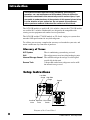
Introduction
This manual contains important safety procedures concerning the
operation, use, and maintenance of this product. Failure to follow the
instructions contained in this manual may result in serious injury. If you
are unable to understand any of the contents of this manual, please bring
it to the attention of your supervisor. Do not operate this equipment
unless you have read and understood the contents of this manual.
The 34700-2K models are used for R-134a vehicles, whereas the 17700-2K models
are used for R-12 vehicles. Both models are designed to be compatible with
existing service equipment and standard service procedures.
The 34700-2K and the 17700-2K models are UL-listed, single-pass systems that
meet the SAE specifications for recycled refrigerant.
To validate your warranty, complete the warranty card attached to your unit, and
return it within ten days from date of purchase.
Glossary of Terms
A/C System The air conditioning system being serviced.
Unit The refrigerant recovery/recycling/recharging unit.
Internal Storage Vessel The refillable refrigerant storage vessel designed
specifically for this unit.
Source Tank A disposable tank of new refrigerant used to refill
the internal storage vessel.
Setup Instructions
Low Side
Gauge
INST0925
Diagram of the Control Panel
High Side
Gauge
High Side
Valve
Keypad
Main Power
Switch
Low Side
Valve

3
34700-2K/17700-2K Cool-Tech Recovery/Recycling/Recharging Unit
240
240
220
220
200
200
180
180
80
80
120
120
100
100
140
140
60
60
20
20
40
40
160
160
3
3
4
4
2
2
1
1
8
8
7
7
6
6
5
5
340
340
320
320
MLS
MLS
280
280
300
300
260
260
12
12
11
11
10
10
9
9
OUNCES
OUNCES
CLOSED
CLOSED
RECOVER
RECOVER
RECOVER
RECOVER
CLOSED
CLOSED
CLOSE
CLOSE
VACUUM
VACUUM
VACUUM
VACUUM
CHARGE
CHARGE
OIL INJECT
OIL INJECT
2
2
0
0
5
5
8
8
MENU
MENU
CLEAR
CLEAR
7
7
1
1
4
4
START
START
RECOVER
RECOVER
VACUUM
VACUUM
F1
F1
ENTER
ENTER
9
9
3
3
6
6
STOP
STOP
CHARGE
CHARGE
VAC-CHARGE
VAC-CHARGE
FLOW
FLOW
LOW
LOW
HIGH
HIGH
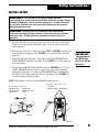
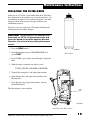
Diagram of Unit’s Components—
Side View
1. 1-800 Phone Number Decal
2. High Side Inlet
3. Low Side Inlet
4. Power Cord with Tag
5. Fill Hose
6. Tank Strap
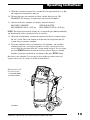
Diagram of Unit’s Components—
Internal View
1. Control Panel Assembly
2. Vacuum Pump
3. Internal Storage Vessel
4. Scale Assembly
5. Oil Drain Bottle
6. Hose Holder
7. Air Purge Control
8. Vacuum Pump Oil Fill
9. Sight Glass
10. Oil Drain
Setup Instructions
2
3
5
4
6
7
1
6
5
2
1
4
3
INST0691
HIGH
HIGH
LOW
LOW
INST0946
8
10
9

© 2001 Robinair, SPX Corporation
4
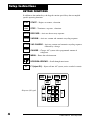
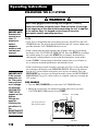
KEYPAD FUNCTIONS
In addition to the number keys, the keypad contains special keys that accomplish
specific operating functions.
Diagram of Keypad
START— Begins, or resumes, a function.
STOP— Terminates, or pauses, a function.
RECOVER— Activates the recovery sequence.
VACUUM— Activates vacuum and automatic recycling sequence.
VAC-CHARGE— Activates vacuum and automatic recycling sequence,
followed by a charge.
CHARGE— Charges A/C system with a programmed amount of
refrigerant.
MENU— Enters the selection menu.
UP/DOWN ARROWS— Scroll through menu items.
F1 (Inject Oil)— Injects oil into A/C system (active at end of vacuum).
F1
Setup Instructions
START
STOP
RECOVER
VACUUM
VAC-CHARGE
CHARGE
MENU
2
2
0
0
5
5
8
8
MENU
MENU
CLEAR
CLEAR
7
7
1
1
4
4
START
START
RECOVER
RECOVER
VACUUM
VACUUM
F1
F1
ENTER
ENTER
9
9
3
3
6
6
STOP
STOP
CHARGE
CHARGE
VAC-CHARGE
VAC-CHARGE

5
34700-2K/17700-2K Cool-Tech Recovery/Recycling/Recharging Unit
Setup Instructions
INITIAL SETUP
CAUTION! R-134a systems have special fittings (per SAE
specifications) to avoid cross-contamination with R-12 systems. Do not
attempt to adapt your unit for another refrigerant — system failure will
result! Read and follow all warnings at the beginning of this manual
before operating the unit.
CAUTION! Avoid the use of an extension cord, because the
extension cord may overheat. However, if you must use an extension
cord, use a No. 14 AWG minimum, and keep the cord as short as
possible.
1. The first time the unit is powered up, it will start in the initial setup mode.
If the initial setup must be performed again, it may be selected using the
menu function.
2. The first step is to select a language. Use the UP and DOWN arrow keys to
select the desired language. Press START to save the currently displayed
language.
3. Next select the operating units. Toggle between UNITS ENGLISH and
UNITS METRIC using the arrow keys. Press START to save the currently
displayed choice.
4. Toggle between BASIC/ADVANCED using the ARROW keys. Use the
BASIC PROMPT option to receive step-by-step, on-screen prompting
through any procedure. Use ADVANCED PROMPT once you know the
procedure and no longer need the step-by-step routine. Press START to
save the currently displayed choice.
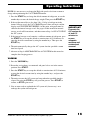
NOTE: This manual is written using the BASIC prompt option
INST0692
1
4
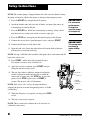
Vacuum Pump Components
1. Oil Filler Tube
2. Pump Exhaust
3. Oil Fill Port
Diagram of Hose Connections
1. Fill Hose
2. Quick-Couplers (34700 Only)
INST0701
4. Sight Glass
5. Oil Drain Fitting
6. Inlet
HIGH
HIGH
LOW
LOW
OPEN
OPEN
CLOSE
CLOSE
2
1
2
3
5
6
IMPORTANT!
You must press
the MENU key
to access all the
functions.

© 2001 Robinair, SPX Corporation
6
240
240
220
220
200
200
180
180
80
80
120
120
100
100
140
140
60
60
20
20
40
40
160
160
3
3
4
4
2
2
1
1
8
8
7
7
6
6
5
5
340
340
320
320
MLS
MLS
280
280
300
300
260
260
12
12
11
11
10
10
9
9
OUNCES
OUNCES
CLOSED
CLOSED
RECOVER
RECOVER
RECOVER
RECOVER
CLOSED
CLOSED
CLOSE
CLOSE
VACUUM
VACUUM
VACUUM
VACUUM
CHARGE
CHARGE
OIL INJECT
OIL INJECT
2
2
0
0
5
5
8
8
MENU
MENU
CLEAR
CLEAR
7
7
1
1
4
4
START
START
RECOVER
RECOVER
VACUUM
VACUUM
F1
F1
ENTER
ENTER
9
9
3
3
6
6
STOP
STOP
CHARGE
CHARGE
VAC-CHARGE
VAC-CHARGE
FLOW
FLOW
LOW
LOW
HIGH
HIGH
Setup Instructions
IMPORTANT!
The pump must
be running
when adding
oil.
IMPORTANT!
For maximum
performance,
change the
vacuum pump
oil frequently.
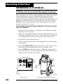
NOTE: The vacuum pump is shipped without oil in the reservoir. Before starting
the pump, oil must be added to the pump, or damage to the pump may occur.
5. Press the START key to begin the oil fill process.
6. Attach the flexible tube and cap to the oil bottle, and pour eight ounces of
vacuum pump oil into the fill port.
7. Press the START key. While the vacuum pump is running, slowly add oil
until the level rises to the center of the reservoir's sight glass.
8. Press the STOP key, and replace the black plastic plug on the fill port.
9. Connect the service hoses, open both panel valves, and press START.
10. Connect the fill hose to a full source tank.
11. Open the tank valve. Invert the tank and install it on the back of the unit,
making sure to secure the tank strap.
NOTE: If using a refillable tank, install the tank upside down, and connect the fill
hose to the vapor valve.
INST0947
1
2
3
1. Oil Fill
2. Sight Glass
3. Oil Drain
12. Press START, and the unit will automatically run a
five-minute vacuum to clear all internal air.
13. After the vacuum is complete, press START to begin
filling the internal storage vessel.
14. The unit stops when a sufficient amount of refrigerant
has been transferred to the internal tank, or when the
source tank is empty. Press the STOP key to pause the
process. Press STOP again to exit, or START to
resume. This process takes 15-20 minutes.
NOTE: Add at least 8 lb. (3.6 kg) of refrigerant before
stopping the process to ensure enough refrigerant is available
for charging.
15. When the fill process is complete, you may press STOP
to exit.
16. The unit is now ready to operate.
NOTE: There is no need to calibrate the scale, because it is
calibrated at the factory.

7
34700-2K/17700-2K Cool-Tech Recovery/Recycling/Recharging Unit
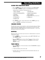
Operating Guidelines
USING THE SELECTION MENU
1. Press the MENU button. The top line of the display reads SETUP MENU.
2. Use the UP and DOWN arrow keys to scroll through the menu choices
displayed on the second line. The menu choices are:
1. SELECT LANGUAGE 7. VACUUM OIL TIME
2. SELECT UNITS (ENGLISH/METRIC) 8. CHANGE VACUUM PUMP OIL
3. TANK REFILL 9. SELECT PROMPTS
4. RECYCLE ONLY 10. CHANGE DEFAULTS
(password protected)
5. FILTER CAPACITY 11. VERSION X.XX
6. CHANGE FILTER
3. Press START to make a choice from the menu. Press STOP to pause any
process, and STOP a second time to exit any process.
CHANGE FILTER
The filter-drier removes acid, particulates, and water from the refrigerant. Change
the filter-drier after 150 pounds (68 kg) of refrigerant has been filtered. See the
REPLACING THE FILTER DRIER section on the following page, as well as the
Maintenance Section, for instructions.
RECYCLE
Manual recycling may be necessary if excessive air and/or moisture is recovered
from the A/C system.
1. Press the MENU key. Use the arrow keys to select RECYCLE ONLY, and
press START to begin.
2. Press the START button to start recycling. To pause recycling, press the
STOP key. To terminate recycling, press the STOP key again, or press
START to resume.
TANK REFILL
1. Press the MENU key. Use the arrow keys to select TANK REFILL, and press
START to begin.
2. Connect the fill hose to the source tank.
3. Open the tank valve. Invert the tank, install it on the back of the unit, and
secure the tank strap.

© 2001 Robinair, SPX Corporation
8
NOTE: If using a refillable tank, install the tank upside down, and connect the fill
hose to the vapor valve.
4. Press the START key, and the tank automatically refills. The unit stops when
a sufficient amount of refrigerant has been transferred to the internal tank, or
if the source tank is empty. Press the STOP key to pause the process. Press
STOP again to exit, or START to resume.
5. When the fill process is complete, press STOP to exit.
VACUUM OIL TIME
This function displays how long the vacuum pump has run since the last oil
change.
1. Press the MENU key. Use the arrow keys to select VACUUM OIL TIME, and
press START to begin.
2. The display reads: OIL TIME = XX:XX This shows how long the pump has
run since the last oil change. The time resets to zero after a VACUUM PUMP
OIL CHANGE. See page 20 of this manual for details.
3. Press STOP to exit.
FILTER CAPACITY
This function is used to show the operator how many pounds or kilograms of
refrigerant have been recovered since the last filter change.
1. Press the MENU key. Use the arrow keys to select FILTER CAPACITY, and
press START to begin.
2. The display reads: FILTERED= XXXlbs(kg). This shows how much
refrigerant has passed through the filter. The amount filtered resets to zero
after a FILTER CHANGE. See page 19 of this manual for details.
3. Press STOP to exit.
SELECT PROMPT (BASIC/ADVANCED)
Use the BASIC PROMPT option to receive step-by-step, on-screen prompting
through any procedure. Use ADVANCED PROMPT once you know the procedure
and no longer need the step-by-step routine.
1. Press the MENU key. Use the arrow keys to choose SELECT PROMPT, and
press START to begin.
2. Toggle between BASIC/ADVANCED using the ARROW keys.
3. Press START to save the current choice and exit.
NOTE: This manual is written for the BASIC PROMPT option.
Operating Guidelines

9
34700-2K/17700-2K Cool-Tech Recovery/Recycling/Recharging Unit
SELECTING A UNIT (METRIC/ENGLISH)
1. Press the MENU key. Use the arrow keys to choose SELECT UNITS, and
press START to begin.
2. Toggle between UNITS ENGLISH and UNITS METRIC using the arrow
key.
3. Press START to save the current choice and exit.
LANGUAGE SELECT
The operator can choose between English, Spanish, French, Italian, or German.
1. Press the MENU key. Use the arrow keys to choose SELECT LANGUAGE,
and press START to begin.
2. Use the UP and DOWN arrows to scroll through the languages.
3. Press START to save the current choice. Press STOP to exit without saving.
CHANGE DEFAULTS
For service use only.
VERSION
Displays the current software revision.
Operating Guidelines

© 2001 Robinair, SPX Corporation
10
VACUUM
VACUUM
RECOVER
RECOVER
CLOSED
CLOSED
CLOSED
CLOSED
VACUUM
VACUUM
RECOVER
RECOVER
STOP
STOP
R-134A
R-134A
in Hg
in Hg
VAC
VAC
psi
psi
kPa
kPa
bar
bar
OIL INJECT
OIL INJECT
CHARGE
CHARGE
0
0
psi
psi
kPa
kPa
bar
bar
R-134A
R-134A
0
0
4
4
5
5
3
3
0
0
0
0
5
5
2
2
0
0
0
0
0
0
4
4
0
0
0
0
0
0
0
0
5
5
3
3
START
START
MENU
MENU
8
8
0
0
CLEAR
CLEAR
7
7
ENTER
ENTER
9
9
2
2
5
5
1
1
4
4
3
3
6
6
RECOVER
RECOVER
VACUUM
VACUUM
VAC-CHARGE
VAC-CHARGE
I
I
0
0
F1
F1
CHARGE
CHARGE
0
0
0
0
8
8
0
0
0
0
1
1
2
2
3
3
0
0
0
0
1
1
2
2
0
0
5
5
3
3
0
0
0
0
0
0
3
3
0
0
0
0
1
1
0
0
2
2
0
0
1
1
2
2
0
0
E
E
R
R
0
0
4
4
8
8
2
2
T
T
A
A
R
R
D
D
0
0
8
8
0
0
7
7
8
8
6
6
4
4
3
3
0
0
4
4
0
0
0
0
0
0
5
5
5
5
0
0
0
0
4
4
6
6
0
0
0
0
0
0
6
6
7
7
0
0
0
0
0
0
0
0
1
1
0
0
1
1
0
0
1
1
0
0
0
0
0
0
7
7
0
0
1
1
0
0
0
0
5
5
0
0
1
1
0
0
0
0
5
5
0
0
1
1
0
0
0
0
9
9
5
5
0
0
2
2
0
0
0
0
1
1
0
0
0
0
0
0
4
4
3
3
5
5
0
0
5
5
0
0
1
1
0
0
0
0
0
0
3
3
2
2
5
5
0
0
2
2
0
0
0
0
5
5
1
1
5
5
2
2
2
2
0
0
5
5
0
0
0
0
3
3
HIGH
HIGH
Operating Guidelines
USING THE CONTROL PANEL
The control panel has various components that control specific operating functions.
MAIN POWER SWITCH—Supplies electrical power to the control panel.
DIGITAL DISPLAY—Used on the visual interface between the operator and
the machine.
LOW SIDE MANIFOLD GAUGE—Connects to an A/C system and shows the
system’s low side pressure.
HIGH SIDE MANIFOLD GAUGE—Connects to an A/C system and shows the
system’s high side pressure.
LOW SIDE VALVE—Controls the low side flow from the A/C system through
the unit.
HIGH SIDE VALVE—Controls the high side flow from the A/C system through
the unit. It has three positions: 1) Recover/Vacuum, 2) Closed, 3) Oil Inject/Charge.
5. Main Power Switch
6. Low Side Valve
7. High Side Valve
1. Low Side Gauge
2. High Side Gauge
3. Display
4. Bezel & Keypad Assembly
INST0926
1
2
3
4
6
7
Diagram of Control Panel
5

11
34700-2K/17700-2K Cool-Tech Recovery/Recycling/Recharging Unit
Operating Instructions
OPERATING TIPS
Follow the SAE-J1991 recommended service procedure for the containment of
R-12, and the SAE-J2210 recommended service procedure for the containment of
R-134a.
The recovery compressor is not a vacuum pump. The compressor pulls the A/C
system to a partial vacuum only. You must use the unit’s vacuum cycle to remove
moisture from the A/C system. We recommend a minimum 15-minute vacuum, or
follow the system manufacturer's recommendations.
This unit is designed to be used with the manifold gauge set built into the
control panel.
The unit includes a 6 cfm (142 l/m) Robinair high vacuum pump for fast, thorough
evacuation. Change the vacuum pump oil after every 10 hours of use.
R-134a systems require special oils. Refer to the A/C system manufacturer’s
service manuals for oil specifications.
Pressing the START and STOP keys together for several seconds will exit any
mode and reset the control.
NOTE: The following operating instructions are written to be used with the
BASIC PROMPTS mode of operation. It is recommended that the BASIC
PROMPTS mode is used until the operator becomes very familiar with the
operation of the unit. See the OPERATING GUIDELINES section of this manual
for instructions on how to select between BASIC PROMPTS and ADVANCED
PROMPTS.

© 2001 Robinair, SPX Corporation
12
RECOVER
RECOVER
VACUUM
VACUUM
CLOSED
CLOSED
RECOVER
RECOVER
VACUUM
VACUUM
CLOSED
CLOSED
VAC-CHARGE
VAC-CHARGE
ENTER
ENTER
R-134A
R-134A
R-134A
R-134A
in Hg
in Hg
VAC
VAC
psi
psi
bar
bar
kPa
kPa
psi
psi
bar
bar
kPa
kPa
RECOVER
RECOVER
CHARGE
CHARGE
OIL INJECT
OIL INJECT
0
0
0
0
3
3
0
0
0
0
5
5
4
4
0
0
0
0
2
2
0
0
0
0
0
0
5
5
0
0
0
0
4
4
3
3
5
5
4
4
7
7
CLEAR
CLEAR
MENU
MENU
8
8
0
0
1
1
5
5
2
2
VACUUM
VACUUM
START
START
I
0
F1
F1
9
9
6
6
3
3
CHARGE
CHARGE
STOP
STOP
0
0
0
0
2
2
0
0
0
0
0
0
1
1
0
0
3
3
0
0
2
2
1
1
0
0
0
0
4
4
7
7
5
5
0
0
2
2
3
3
0
0
R
R
5
5
3
3
0
0
0
0
4
4
0
0
0
0
2
2
8
8
3
3
2
2
1
1
0
0
3
3
0
0
4
4
0
0
4
4
0
0
8
8
2
2
1
1
0
0
D
D
R
R
A
A
T
T
E
E
0
0
8
8
0
0
1
1
1
1
0
0
0
0
0
0
0
0
8
8
7
7
6
6
0
0
0
0
0
0
5
5
6
6
0
0
7
7
0
0
0
0
1
1
0
0
0
0
9
9
0
0
1
1
0
0
5
5
5
5
1
1
0
0
0
0
1
1
5
5
0
0
0
0
0
0
0
0
0
0
0
0
5
5
0
0
0
0
1
1
0
0
5
5
0
0
2
2
1
1
0
0
5
5
0
0
0
0
1
1
3
3
0
0
0
0
5
5
0
0
4
4
0
0
0
0
2
2
0
0
5
5
0
0
2
2
0
0
3
3
0
0
6
6
0
0
2
2
5
5
0
0
HIGH
HIGH
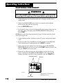
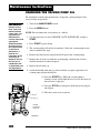
RECOVERING REFRIGERANT
WARNING
Wear safety goggles when working with refrigerant. Read and follow
all warnings at the beginning of this manual before operating the unit.
1. Connect the power cord to the back of the unit, and plug it into the correct
voltage outlet.
2. Turn on the MAIN POWER and, if necessary, empty the oil drain bottle
located on the right hand side of the unit.
3. Press the RECOVER button.
4. If 150 pounds (68 kg) or more of refrigerant has been recovered since the last
filter-drier change, the display reads FILTER WEIGHT XXX lb (XX kg).
Press START.
NOTE: Refer to the filter change procedure on page 19 of this manual for details
about replacing the filter.
5. Connect the high and low side hoses to the A/C system, and open the coupler
valves.
6. Put the Low Side Valve in the Recover/Vacuum position. Put the High Side
Valve in the Recover/Vacuum position. Press START to continue.
7. If the system pressure is below 25 psi, the display reads: LOW SYSTEM
PRESSURE until the pressure increases or the START button is pressed. You
may press STOP to exit at this point.
8. If the unit has refrigerant in the low-side plumbing, it begins the clearing
process and displays CLEARING IN PROGRESS. If you wish to skip the
clearing operation or stop the clearing prematurely, press the START key.
Diagram of Control Panel
During Recovery
Manifold Gauges
Valves Open
Operating Instructions
INST0928
Recover

13
34700-2K/17700-2K Cool-Tech Recovery/Recycling/Recharging Unit
Operating Instructions
INST0699
9. When the system has recovered to a vacuum level of approximately 13 in. Hg.,
the compressor automatically shuts off.
10. The unit then goes into automatic oil drain, and the display reads: OIL
DRAINING. Oil draining can require up to 90 seconds to complete.
11. After the oil drain is complete, the display alternates between:
RECOVERY COMPLETE CHECK OIL BOTTLE
RECOVERED XX.XX lbs. (X.XX kg) RECOVERED XX.XX lbs. (X.XX kg)
NOTE: The displayed recovered weight can vary depending on ambient conditions,
and should not be used as an indicator of scale accuracy.
12. Check the oil drain bottle, and note the amount of oil that was removed from
the A/C system. This is the amount of oil that must be charged into the A/C
system after evacuation is complete.
13. To ensure complete recovery of refrigerant, wait 5 minutes, and watch the
manifold gauges for a rise in pressure above 0 in. Hg. A pressure rise may
occur if there was freezing in the A/C system during recovery. If a rise occurs,
press the START button to resume the recovery process. Repeat as needed
until the system pressure holds for two minutes, then press STOP to exit.
Recovery is now complete. You are now ready to make any repairs to the A/C
system, if necessary, or advance to the Evacuation Process.
Diagram of the Oil
Injection System
1. Oil Injector Bottle
2. Oil Drain Bottle
1
3
3
2
2
1
1
60
60
80
80
20
20
40
40
12
12
220
220
7
7
5
5
4
4
6
6
200
200
180
180
160
160
120
120
140
140
100
100
11
11
9
9
8
8
10
10
320
320
340
340
280
280
300
300
260
260
240
240
OUNCES
OUNCES
360
360
2

© 2001 Robinair, SPX Corporation
14
RECOVER
RECOVER
VACUUM
VACUUM
CLOSED
CLOSED
RECOVER
RECOVER
VACUUM
VACUUM
CLOSED
CLOSED
VAC-CHARGE
VAC-CHARGE
ENTER
ENTER
R-134A
R-134A
R-134A
R-134A
in Hg
in Hg
VAC
VAC
psi
psi
bar
bar
kPa
kPa
psi
psi
bar
bar
kPa
kPa
RECOVER
RECOVER
CHARGE
CHARGE
OIL INJECT
OIL INJECT
0
0
0
0
3
3
0
0
0
0
5
5
4
4
0
0
0
0
2
2
0
0
0
0
0
0
5
5
0
0
0
0
4
4
3
3
5
5
4
4
7
7
CLEAR
CLEAR
MENU
MENU
8
8
0
0
1
1
5
5
2
2
VACUUM
VACUUM
START
START
I
I
0
0
F1
F1
9
9
6
6
3
3
CHARGE
CHARGE
STOP
STOP
0
0
0
0
2
2
0
0
0
0
0
0
1
1
0
0
3
3
0
0
2
2
1
1
0
0
0
0
4
4
7
7
5
5
0
0
2
2
3
3
0
0
R
R
5
5
3
3
0
0
0
0
4
4
0
0
0
0
2
2
8
8
3
3
2
2
1
1
0
0
3
3
0
0
4
4
0
0
4
4
0
0
8
8
2
2
1
1
0
0
D
D
R
R
A
A
T
T
E
E
0
0
8
8
0
0
1
1
1
1
0
0
0
0
0
0
0
0
8
8
7
7
6
6
0
0
0
0
0
0
5
5
6
6
0
0
7
7
0
0
0
0
1
1
0
0
0
0
9
9
0
0
1
1
0
0
5
5
5
5
1
1
0
0
0
0
1
1
5
5
0
0
0
0
0
0
0
0
0
0
0
0
5
5
0
0
0
0
1
1
0
0
5
5
0
0
2
2
1
1
0
0
5
5
0
0
0
0
1
1
3
3
0
0
0
0
5
5
0
0
4
4
0
0
0
0
2
2
0
0
5
5
0
0
2
2
0
0
3
3
0
0
6
6
0
0
2
2
5
5
0
0
HIGH
HIGH
Operating Instructions
EVACUATING THE A/C SYSTEM
WARNING
Wear safety goggles when working with refrigerant. Use only
authorized refillable refrigerant tanks. Read and follow all warnings
at the beginning of this manual before operating the unit. In addition
to the number keys, the keypad contains special keys that
accomplish specific operating functions.
NOTE:
• If any oil was drained from the system during recovery, DO NOT use the VAC-
CHARGE feature. The oil must be replenished into the A/C system, which is not
possible when the VAC-CHARGE function is used.
• If the vacuum pump has been run more than 10 hours since the last oil change,
the display reads: VACUUM OIL TIME XX:XX. Press the STOP key to change
the vacuum pump oil, or press the START key to continue. Instructions for
changing the vacuum pump oil are located in the maintenance section of this
manual. NOTE: Vacuum pump oil should be changed after every 10 hours of
use to maintain maximum performance and endurance levels.
• If the system being evacuated contains a pressure over 25 psi at any point during
the evacuation, the display reads PRESSURE EXISTS. This message indicates
that the A/C system contains refrigerant; press any key to continue. Press the
RECOVERY key to recover any refrigerant in the system (See RECOVERING
REFRIGERANT, page 12). After recovery is complete, return to evacuating the
A/C system.
VAC-CHARGE
1. Press the VAC-CHARGE key to select the VAC-CHARGE feature.
2. Ensure the service hoses are connected and both panel valves are in the
VACUUM/ RECOVER position. Press START.
IMPORTANT!
Evacuate the
system for at
least 15
minutes to
ensure
adequate
moisture and
contaminant
removal.
IMPORTANT!
If the vacuum
pump has run
for 10 or more
hours without
an oil change,
the message
VACUUM OIL
TIME XX:XX
appears on the
display.
Change the
pump oil
following the
procedures in
the
MAINTENANCE
INSTRUCTIONS.
Vacuum
INST0929
The Control Panel
During Evacuation
Vac-Charge

15
34700-2K/17700-2K Cool-Tech Recovery/Recycling/Recharging Unit
NOTE: It is not necessary to change the High side panel valve from vacuum to
charge when performing the VAC-CHARGE function.
3. Press the START key to charge the default amount of refrigerant, or use the
number keys to enter the desired charge weight. Then press the START key.
4. If the weight entered leaves less than 3 lbs (1.36 kg) of refrigerant in the
internal storage vessel, the VAC-CHARGE process does not begin, and the
display reads INSUFFICIENT REFRIG. At this point, refrigerant must be
added to the internal storage vessel. See page 6 of this manual for internal
storage vessel refill instructions, and then return to Step 1 of EVACUATING
the A/C system.
5. If the internal storage vessel contains a sufficient amount of refrigerant, press
the START key to accept the default evacuation time of 15:00 minutes, or
enter the desired vacuum time by using the number keys. Then press the
START key.
6. The unit automatically charges the A/C system after the specified vacuum
time has elapsed.
7. Advance to Step 4 of RECHARGING the A/C SYSTEM in this manual to
complete the charging process.
VACUUM
1. Press the VACUUM key.
2. Ensure the service hoses are connected and panel valves are in the correct
position. Press START.
3. Press the START key to accept the default evacuation time of 15:00 minutes,
or enter the desired vacuum time by using the number keys, and press the
START key.
4. The unit evacuates the A/C system and stops when the specified time has
elapsed. Pressing the STOP key will pause the process. Press START to
resume, or STOP again to exit.
5. You are now ready to replenish the A/C system oil (if necessary), or to
recharge the system with refrigerant.
Operating Instructions
IMPORTANT!
Evacuate the
A/C system for
at least 15
minutes to
ensure
adequate
moisture and
contaminant
removal.

© 2001 Robinair, SPX Corporation
16
RECOVER
RECOVER
VACUUM
VACUUM
CLOSED
CLOSED
RECOVER
RECOVER
VACUUM
VACUUM
CLOSED
CLOSED
VAC-CHARGE
VAC-CHARGE
ENTER
ENTER
R-134A
R-134A
R-134A
R-134A
in Hg
in Hg
VAC
VAC
psi
psi
bar
bar
kPa
kPa
psi
psi
bar
bar
kPa
kPa
RECOVER
RECOVER
CHARGE
CHARGE
OIL INJECT
OIL INJECT
0
0
0
0
3
3
0
0
0
0
5
5
4
4
0
0
0
0
2
2
0
0
0
0
0
0
5
5
0
0
0
0
4
4
3
3
5
5
4
4
7
7
CLEAR
CLEAR
MENU
MENU
8
8
0
0
1
1
5
5
2
2
VACUUM
VACUUM
START
START
I
0
F1
F1
9
9
6
6
3
3
CHARGE
CHARGE
STOP
STOP
0
0
0
0
2
2
0
0
0
0
0
0
1
1
0
0
3
3
0
0
2
2
1
1
0
0
0
0
4
4
7
7
5
5
0
0
2
2
3
3
0
0
R
R
5
5
3
3
0
0
0
0
4
4
0
0
0
0
2
2
8
8
3
3
2
2
1
1
0
0
3
3
0
0
4
4
0
0
4
4
0
0
8
8
2
2
1
1
0
0
D
D
R
R
A
A
T
T
E
E
0
0
8
8
0
0
1
1
1
1
0
0
0
0
0
0
0
0
8
8
7
7
6
6
0
0
0
0
0
0
5
5
6
6
0
0
7
7
0
0
0
0
1
1
0
0
0
0
9
9
0
0
1
1
0
0
5
5
5
5
1
1
0
0
0
0
1
1
5
5
0
0
0
0
0
0
0
0
0
0
0
0
5
5
0
0
0
0
1
1
0
0
5
5
0
0
2
2
1
1
0
0
5
5
0
0
0
0
1
1
3
3
0
0
0
0
5
5
0
0
4
4
0
0
0
0
2
2
0
0
5
5
0
0
2
2
0
0
3
3
0
0
6
6
0
0
2
2
5
5
0
0
HIGH
HIGH
3
3
2
2
1
1
60
60
80
80
20
20
40
40
12
12
220
220
7
7
5
5
4
4
6
6
200
200
180
180
160
160
120
120
140
140
100
100
11
11
9
9
8
8
10
10
320
320
340
340
280
280
300
300
260
260
240
240
OUNCES
OUNCES
360
360
Operating Instructions
REPLENISHING A/C SYSTEM OIL
CAUTION! To prevent air from entering the A/C system, never let the
oil level drop below the pickup tube while charging or replenishing.
Before charging the A/C system, you must replenish any oil removed from the A/C
system during the recovery process. Charge only the amount of oil that was
removed from the A/C system during recovery. Check the oil drain bottle to
determine the amount of oil that was removed during recovery. Empty the oil drain
bottle before recovering the next A/C system to prevent an inaccurate oil charge.
NOTE: If no oil was removed from the A/C system during recovery, DO NOT
charge any oil into the A/C system.
THE VACUUM CYCLE MUST RUN COMPLETELY OR THE OIL INJECT
WILL NOT OPERATE.
1. Select the correct oil for the A/C system being serviced. Refer to the vehicle
manufacturer's service manual.
2. Adjust the o-ring around the oil injector bottle to the required oil charge level.
For example, if the bottle's oil level is at 4 ounces, and you need 1/2 ounce of
oil to replenish the A/C system, place the o-ring at the 3 1/2 ounce level.
3. Reattach the oil injector bottle to the unit.
4. Close the Low Side manifold valve. Put the High Side valve in the Oil Inject/
Charge position.
5. Press the F1 (INJECT OIL) button once and release it when it “beeps.” Press
the F1 button again and hold it until the oil level reaches the o-ring.
6. Press the STOP button after the oil charge is complete to recharge the A/C
system with refrigerant. You must recharge the AC system with refrigerant at
this time to ensure all of the oil is delivered.
Diagram of the Oil Injection System
INST0930
Inject
Oil
Button
Control Panel
INST0699
Oil
Inject
Bottle
Oil
Drain
Bottle

17
34700-2K/17700-2K Cool-Tech Recovery/Recycling/Recharging Unit
Operating Instructions
IMPORTANT!
Evacuate the
A/C system for
at least 15
minutes for
adequate
moisture and
contaminant
removal.
RECHARGING THE A/C SYSTEM
WARNING
1. Press the CHARGE button. (If an oil inject has been performed, the
CHARGE key does not have to be pressed.)
2. Put the Low Side Valve in the Closed position. Put the High Side Valve in
the Oil Inject/Charge position. Press START to continue.
3. Accept either the default weight by pressing START, or type in a weight
with the number keys, and press START.
4. If the weight entered will leave less than 3 lbs (1.36 kg) of refrigerant in the
refrigerant tank, the charge function will not start, and the display reads:
INSUFFICIENT REFRIG.
PRESS ANY KEY TO EXIT
See the Operating Guidelines section of the manual for refill instructions.
5. Upon entering a valid charge weight, the display reads:
CHARGE IN PROGRESS
CHARGED= X.XX lbs. (X.XX kg)
6. If, during the charge cycle, the weight fails to charge 0.05 lbs (0.02 kg) in 30
seconds, the unit intermittently beeps while the display alternates between:
CHARGING HAS SLOWED CHARGE HAS SLOWED
PRESS START TO RETRY OR STOP TO EXIT
7. Pressing the START button when the charging is slowed causes the charge
to resume. If charging does not complete, see the SLOW CHARGE
PROCEDURE below.
8. When the charge is complete the display will show
CHARGE COMPLETE
X.XXlb (kg) CHARGED
9. For R-134a systems, close the high and low side coupler valves. Remove the
service hoses from the A/C system.
The A/C system is now ready for use.
Wear safety goggles when working with refrigerant. Use only
authorized refillable refrigerant tanks. Disconnect hoses with
extreme caution! All hoses may contain liquid refrigerant under
pressure. Read and follow all warnings at the beginning of this
manual before operating the unit.

© 2001 Robinair, SPX Corporation
18
SLOW CHARGE PROCEDURE
WARNING
Before starting the vehicle's engine, verify that it is in PARK or
NEUTRAL, with the emergency brake ON.
Never run a vehicle without adequate ventilation in the work area.
CAUTION! Close the high side manifold valve before starting the
vehicle A/C system.
1. Close the High Side Valve. Put the Low Side Valve in the Recover/Vacuum
position.
2. Start the vehicle, and set the AC system to its maximum setting.
3. Press START. The unit charges out of the low side inlet only, allowing the
vehicle's compressor to pull the refrigerant into the A/C system.
4. When the unit is finished charging, the display reads:
CHARGE COMPLETE
X.XX lb (kg) CHARGED
5. Close the LOW SIDE manifold valve.
6. Turn off the vehicle's engine.
7. For R-134a systems, close the high and low side coupler valves. Remove the
service hoses from the A/C system.
The A/C system is now ready for use.
Operating Instructions
Page is loading ...
Page is loading ...
Page is loading ...
Page is loading ...
Page is loading ...
Page is loading ...
Page is loading ...
Page is loading ...
Page is loading ...
Page is loading ...
Page is loading ...
Page is loading ...
-
 1
1
-
 2
2
-
 3
3
-
 4
4
-
 5
5
-
 6
6
-
 7
7
-
 8
8
-
 9
9
-
 10
10
-
 11
11
-
 12
12
-
 13
13
-
 14
14
-
 15
15
-
 16
16
-
 17
17
-
 18
18
-
 19
19
-
 20
20
-
 21
21
-
 22
22
-
 23
23
-
 24
24
-
 25
25
-
 26
26
-
 27
27
-
 28
28
-
 29
29
-
 30
30
-
 31
31
-
 32
32


SPX Cooling Technologies 17700-2K User manual
- Type
- User manual
- This manual is also suitable for
Ask a question and I''ll find the answer in the document
Finding information in a document is now easier with AI
Other documents
-
Kmart 43127887 User manual
-
Cornwell Tools RAC34788 Owner's manual
-
MasterCool 91585-B-YF Operating instructions
-
-
-
-
-
-
Robinair 34788NI-230 Operating instructions
-