9
Gas Supply Requirements
Observe all governing codes and ordinances.
IMPORTANT: This installation must conform with all local codes
and ordinances. In the absence of local codes, installation must
conform with American National Standard, National Fuel Gas
Code ANSI Z223.1 - latest edition or CAN/CGA B149 - latest
edition.
IMPORTANT: Leak testing of the cooktop must be conducted
according to the manufacturer’s instructions.
Type of Gas
Natural Gas:
This cooktop is factory set for use with Natural gas. If converting
to LP gas, see the “LP Gas Conversion” instructions provided in
the package containing literature. The model/serial/rating plate
located on bottom of the cooktop has information on the types
of gas that can be used. If the types of gas listed do not include
the type of gas available, check with the local gas supplier.
LP Gas Conversion:
Conversion must be done by a qualified service technician.
No attempt shall be made to convert the cooktop from the gas
specified on the model/serial/rating plate for use with a different
gas without consulting the serving gas supplier. See the “Gas
Conversion” instructions provided in the package containing
literature.
Gas Supply Line
■ Provide a gas supply line of
3
⁄
4
" (1.9 cm) rigid pipe to the
cooktop location. A smaller size pipe on longer runs may
result in insufficient gas supply. Pipe-joint compounds
that resist the action of LP gas must be used. Do not use
TEFLON
®†
tape. With LP gas, piping or tubing size should be
1
/
2
" minimum. Usually, LP gas suppliers determine the size
and materials used in the system.
Flexible metal appliance connector:
■ If local codes permit, use a
1
/
2
" or
3
/
4
" I.D. flexible stainless
steel tubing gas connector, designed by CSA to connect the
cooktop to the rigid gas supply line.
■ A
1
/
2
" male pipe thread is needed for connection to the
female pipe threads of the inlet to the cooktop pressure
regulator.
■ Do not kink or damage the flexible metal tubing when
moving the cooktop.
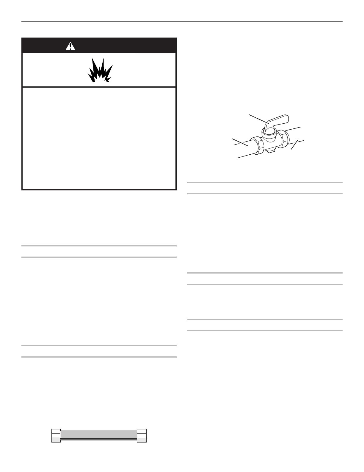
■ Must include a shut-off valve:
The supply line must be equipped with a manual shut-off
valve. This valve should be located in the same room. It must
be accessible without removing the cooktop, and it should
be in a location that allows ease of opening and closing. Do
not block access to shut-off valve. The valve is for turning on
or shutting off gas to the cooktop.
Gas Pressure Regulator
The gas pressure regulator supplied with this cooktop must be
used. The inlet pressure to the regulator should be as follows
for proper operation:
Natural Gas:
Minimum pressure: 5" (12.7 cm) WCP
Maximum pressure: 7" to 14" (17.8 cm to 35.5 cm) WCP
LP Gas:
Minimum pressure: 10" (25.4 cm) WCP
Maximum pressure: 14" (35.5 cm) WCP
Contact local gas supplier if you are not sure about the inlet
pressure.
Burner Input Requirements
Input ratings shown on the model/serial/rating plate are for
elevations up to 2,000 ft (609.6 m).
For elevations above 2,000 ft (609.6 m), ratings should be
reduced at a rate of 4% for each 1,000 ft (304.8 m) above
sea level (not applicable for Canada).
Gas Supply Pressure Testing
Gas supply pressure for testing regulator must be at least 1"
water column pressure above the manifold pressure shown on
the model/serial/rating plate.
Line pressure testing above ½ psi gauge (14" WCP)
The cooktop and its individual shut-off valve must be
disconnected from the gas supply piping system during any
pressure testing of that system at test pressures in excess
of
1
/
2
psi (3.5 kPa).
Line pressure testing at ½ psi gauge (14" WCP) or lower
The cooktop must be isolated from the gas supply piping
system by closing its individual manual shut-off valve during
any pressure testing of the gas supply piping system at test
pressures equal to or less than
1
/
2
psi (3.5 kPa).
WARNING
Explosion Hazard
Use a new CSA International approved gas supply line.
Install a shut-off valve.
Securely tighten all gas connections.
If connected to LP, have a qualified person make sure
gas pressure does not exceed 14" (36 cm) water
column.
Examples of a qualified person include:
licensed heating personnel,
authorized gas company personnel, and
authorized service personnel.
Failure to do so can result in death, explosion, or fire.
B
A
C
A. Gas supply line
B. Shut-off valve open position
C. To cooktop
†
®
TEFLON is a registered trademark of Chemours.


