
Owner
'
s Manual
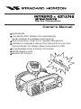
Submersible
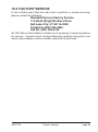
One-Button DSC Distress Call Automatically
Sends Latitude & Longitude and Vessel ID
Noise Canceling “Clear Voice” Speaker Microphone
Latitude & Longitude & Speed Over Ground & Course Over
Ground Shown On Display When Connected To GPS
Programmable Scan & Priority Ch16 Scan
NOAA Weather Alert
Backlit LCD & Keys
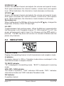
INTREPID + GX1270S
25 Watt VHF/FM
Marine Transceiver
16/9
SCAN
NAV
WX
H/L
CALL
/SET
16/9
INTREPID+
VOL/PWR
SQL
DISTRESS
PULL OPEN

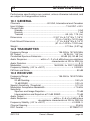
TABLE OF CONTENTS
FCC RADIO LICENSE INFORMATION ...... 1
STATION LICENSE ..................................... 1
RADIO CALL SIGN ...................................... 1
CANADIAN SHIP STATION LICENSING .... 1
FCC NOTICE ................................................ 2
1 GENERAL INFORMATION ................. 3
1.1 INTRODUCTION ................................. 3
1.2 FCC/ INDUSTRY CANADA
INFORMATION .................................... 3
2 ACCESSORIES .................................... 4
2.1 PACKING LIST .................................... 4
2.2 OPTIONS ............................................. 4
3 CONTROLS AND INDICATORS ......... 5
3.1 CONTROLS AND CONNECTIONS .... 5
4 INSTALLATION ................................. 10
4.1 LOCATION ......................................... 10
4.2 ELECTRICAL CONNECTIONS ......... 10
4.3 ACCESSORY CABLE ....................... 11
4.3.1 Cable pin number and signal ..... 11
4.4 OPTIONAL CMB16 FLUSH MOUNT
INSTALLATION ................................. 12
5 BASIC OPERATION .......................... 13
5.1 RECEPTION ...................................... 13
5.2 TRANSMISSION ................................ 13
5.3 TRANSMIT TIME - OUT TIMER (TOT) .. 14
5.4 SIMPLEX/DUPLEX CHANNEL USE . 14
5.5 USA, CANADA, AND INTERNATIONAL
MODE ................................................ 14
5.6 NOAA WEATHER CHANNELS ......... 15
5.7 NOAA WEATHER ALERT ................. 15
5.8 MEMORY SCANNING (M-SCAN) ..... 16
5.9 PRIORITY SCANNING (P-SCAN) .... 16
5.10 NAVIGATION INDICATION ............... 17
5.11 VOICE SCRAMBLER ........................ 18
5.11.1 Operation with voice scrambler .. 18
5.12 RESETTING THE TRANSCEIVER’S
MICROPROCESSOR ........................ 18
6 DIGITAL SELECTIVE CALLING ....... 19
6.1 GENERAL .......................................... 19
6.1.1 Digital Selective Calling (DSC) ... 19
6.1.2 Maritime Mobile Service Identity
(MMSI) ........................................ 19
6.2 SENDING A DISTRESS CALL .......... 20
6.2.1 Sending a Distress Call
Automatically............................... 20
6.2.2 Sending a Distress Call and
Manually Inputting a Position ..... 21
6.3 SENDING AN INDIVIDUAL CALL ..... 22
6.4 SENDING A GROUP CALL ............... 23
6.5 SENDING AN ALL SHIPS CALL ....... 24
6.6 SENDING A DSC TELEPHONE CALL .. 25
6.6.1 Operation of Telephone Call ...... 25
6.6.2 Resend Telephone Call Signal ... 26
6.6.3 Resend Telephone Call When
Receive Busy Signal ................... 26
6.7 DSC STANDBY ................................. 27
6.8 CALL WAITING DIRECTORY ........... 27
6.8.1 Operation of Distress Call Waiting ... 28
6.7.2 Operation of Individual Call Waiting .. 28
6.9 POSITION REQUEST ....................... 29
6.10 POSITION SEND ............................... 30
6.11 RECEIVING DSC CALLS .................. 31
6.11.1 Receiving a distress call ............. 31
6.11.2 Receiving a distress relay call .... 32
6.11.3 Receiving an all ships call .......... 32
6.11.4 Receiving a geographical area call .. 32
6.11.5 Receiving an individual call ........ 33
6.11.6 Receiving a position request ...... 33

7. DSC / RADIO SETUP MODE ............ 34
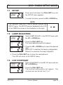
7.1 SETUP ............................................... 34
7.2 LAMP ADJUSTING ............................ 34
7.3 LCD CONTRAST ............................... 34
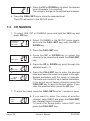
7.4 CH NAMING ...................................... 35
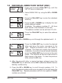
7.5 INDIVIDUAL DIRECTORY SETUP
(DSC) ................................................. 36
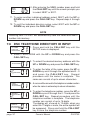
7.6 DSC TELEPHONE DIRECTORY ID
INPUT ................................................ 37
7.7 POSITION REQUEST REPLY TYPE 38
7.8 VOICE SCRAMBLER ........................ 39
7.9 KEY BEEP (ON OR OFF) ................. 40
7.10 INDIVIDUAL RING ............................. 40
7.11 TIME OFFSET ................................... 41
7.12 USER MMSI INPUT ........................... 42
7.13 GROUP MMSI INPUT ....................... 43
7.14 DSC SCANNING ............................... 44
TO CHANGE DSC SCAN METHOD: ..... 44
8 RAM MIC OPERATION ..................... 45
8.1 RAM MIC CONTROLS AND
CONNECTIONS ................................ 45
8.2 INDICATORS ..................................... 47
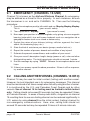
8.3 INTERCOM OPERATION .................... 48
8.3.1 Communication ........................... 48
8.3.2 Calling ......................................... 48
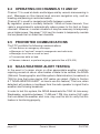
9 OPERATING PRACTICES ................ 49
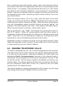
9.1 EMERGENCY (CHANNEL 16 USE) ... 49
9.2 CALLING ANOTHER VESSEL
(CHANNEL 16 OR 9) ......................... 49
9.3 MAKING TELEPHONE CALLS ......... 50
9.4 OPERATING ON CHANNELS 13 AND
67 ....................................................... 51
9.5 PROHIBITED COMMUNICATIONS .. 51
9.6 NOAA WEATHER ALERT TESTING ... 51
9.7 DIGITAL SELECTIVE CALLING (DSC) ... 52
9.7.1 USCG DSC Watch ...................... 52
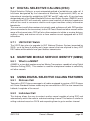
9.8 MARITIME MOBILE SERVICE
IDENTITY (MMSI) .............................. 52
9.8.1 What is a MMSI? ........................ 52
9.9 USING DIGITAL SELECTIVE CALLING
FEATURES ........................................ 52
9.9.1 Distress Call ................................ 52
9.9.2 Individual Call ............................. 52
9.9.3 Group Call ................................... 53
9.9.4 Urgency Call ............................... 53
9.9.5 Safety Call ................................... 53
9.9.6 Position request .......................... 53
9.9.7 Telephone Call ............................ 53
9.10 ADDITIONAL DIGITAL SELECTIVE
CALLING INFORMATION ................. 53
9.11 ABOUT VHF RADIO .......................... 53
9.12 SELECTING AN ANTENNA .............. 54
9.13 COAXIAL CABLE .............................. 54
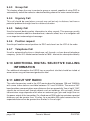
10 MAINTENANCE ................................. 55
10.1 REPLACEMENT PARTS ................... 55
10.2 FACTORY SERVICE ......................... 56
10.3 TROUBLESHOOTING CHART ......... 57
10.4 CONNECTION OF GPS WITH NMEA
OUTPUT ............................................ 58
11. CHANNEL ASSIGNMENTS .............. 59
12. WARRANTY ....................................... 63
13 SPECIFICATIONS ............................. 66
10.1 GENERAL .......................................... 66
10.2 TRANSMITTER ................................. 66
10.3 RECEIVER ......................................... 66

page 1 Owner’s Manual GX1270S
ON-LINE WARRANTY REGISTRATION
Please visit www.standardhorizon.com to register the INTREPID+
Marine VHF. It should be noted that visiting the Web site from time to
time may be beneficial to you, as new products are released they will
appear on the STANDARD HORIZON Web site. Also a statement
regarding product support should be added to the manual.
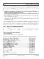
PRODUCT SUPPORT INQUIRIES
If you have any questions or comments regarding the use of the INTREPID+,
you can visit the STANDARD HORIZON Web site to send an E-Mail or
contact the Product Support team at 562/404-2700 M-F 7:00-5:00PST.
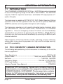
FCC RADIO LICENSE INFORMATION
Standard Horizon radios comply with the Federal Communication Commission (FCC)
requirements that regulate the Maritime Radio Service.
STATION LICENSE
An FCC ship station license is no longer required for any vessel traveling in U.S. waters
which uses a VHF marine radio, RADAR or EPIRB, and which is not required to carry radio
equipment. However, any vessel required to carry a marine radio on an international voyage,
carrying a HF single side band radiotelephone or marine satellite terminal. FCC license
forms, including applications for ship (506) and land station licenses can be downloaded
via the Internet at www.fcc.gov/forms. To obtain a form from the FCC, call (888) 225-5322.
RADIO CALL SIGN
Currently the FCC does not require recreational boaters to have a Ship Radio Station
License. The USCG recommends the boats registration number and the state to be used.
CANADIAN SHIP STATION LICENSING
You do not need a license if your vessel is not operated in sovereign waters of a
country other than Canada or the U.S.A. If you do need a license contact their nearest
field office or regional office or write:
Industry Canada
Radio Regulatory Branch
Attn: DOSP
300 Slater Street
Ottawa, Ontario
Canada, KIA 0C8

GX1270S Owner’s Manual page 2
FCC NOTICE
NOTICE
Unauthorized changes or modifications to this equipment may void
compliance with FCC Rules. Any change or modification must be
approved in writing by STANDARD HORIZON.
NOTICE
This equipment has been tested and found to comply with the limits for
a Class B digital device, pursuant to Part 15 of the FCC Rules. These
limits are designed to provide reasonable protection against harmful
interference in a residential installation. This equipment generates,
uses and can radiate radio frequency energy and, if not installed and
used in accordance with the instructions, may cause harmful
interference to radio communications. However, there is no guarantee
that interference will not occur in a particular installation. If this
equipment does cause harmful interference to radio or television
reception, which can be determined by turning the equipment off and
on, the user is encouraged to try to correct the interference by one or
more of the following measures:
— Reorient or relocate the receiving antenna.
— Increase the separation between the equipment and receiver.
— Connect the equipment into an outlet on a circuit different from
that to which the receiver is connected.
— Consult the dealer or an experienced radio/TV technician for
help.

page 3 Owner’s Manual GX1270S
1 GENERAL INFORMATION
1.1 INTRODUCTION
The STANDARD HORIZON GX1270S is a VHF/FM transceiver designed
for use in the frequency range of 156.025 to 163.275 MHz. The GX1270S
requires 13.8V for operation and has a switchable RF output power of 1
watt or 25 watts.
The transceiver is capable of RTCM SC101 DSC (Digital Selective Calling)
operation and intercom operation with the use of an optional RAM mic
(CMP23) (remote-control speaker/microphone with display).
The transceiver operates on all currently-allocated marine channels which
are switchable for use with either USA, International, or Canadian
regulations. It has an emergency channel 16 which can be immediately
selected from any channel by pressing the red 16/9 key. NOAA Weather
channels can also be accessed immediately by pressing the WX key with
channel selection.
Other features of the transceiver include: scanning, priority scanning,
submersible noise-canceling speaker mic, high and low voltage warning,
and GPS repeatability.
1.2 FCC/ INDUSTRY CANADA INFORMATION
The following data pertaining to the transceiver is necessary to fill out the
license application.
Type Acceptance ................................................................... FCC Part 80
Output Power .......................................... 1 Watt (low) and 25 Watts (high)
Emission..................................................................... 16K0F3E, 16K0G3E
Frequency Range ............................................... 156.025 to 163.275 MHz
FCC Type Number ............................................................... K66GX1270S
Industry Canada Type Approval ................................................ PENDING
Additional FCC and Industry Canada data, including licensing
requirements, are contained in the companion document titled
OWNER’S MANUAL SUPPLEMENT. The document also contains
charts for VHF channel assignments, transceiver procedures,
maintenance, factory service information, and warranty data.

GX1270S Owner’s Manual page 4
2 ACCESSORIES
2.1 PACKING LIST
When the package containing the transceiver is first opened, please check
it for the following contents:
• GX1270S INTREPID+ Transceiver (White/Black)
• CMP351W/CMP351B (White/Black Microphone attached to the
transceiver) and hanger kit
• Mounting Bracket and attaching hardware
• Spare Fuse (6 A, 250 V )
• Owner’s Manual
• Owner’s Manual Supplement
• Quick-Reference Card
• Accessory Cable
• Power Cord
• Dust Cover
2.2 OPTIONS
CMB16 ...................................................................... Flush-Mount Bracket
CMP23 ........................................ Remote-Access Microphone (RAM Mic)
CAW23 ............................................ 10-foot Extension Cable for RAM Mic
101S ...................................................................... Mini Extension Speaker
201S ............................................................................. Extension Speaker
201SZ...................................................... Flush Mount Extension Speaker
CVS2500 .......................................................................... Voice Scrambler
201SBK .............................................................. Black Extension Speaker
201SBKZ ........................................ Flush Mount Black Extension Speaker

page 5 Owner’s Manual GX1270S
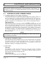
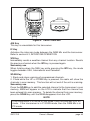
3 CONTROLS AND INDICATORS
NOTE
This section defines each control of the transceiver. See Figure 1 for
location of controls. For detailed operating instructions refer to chapter
4 of this manual.
3.1 CONTROLS AND CONNECTIONS
q POWER SWITCH/VOLUME CONTROL
Turns the transceiver on and off as well as adjusts the audio volume. To
turn the transceiver on press and hold this knob until the LCD turns on.
To turn it off, press and hold this knob until the LCD turns off. When the
power is turned on, the transceiver is set to the last selected channel.
Secondary Use
When the transceiver is turned on while the SCAN and WX keys are held
down, the internal microprocessor is reset. This clears the memory and all
user-programmed settings, such as scan memory,, priority scan
assignments, and A/B channel assignments. This condition is known as
the default condition, the same as when shipped from the factory. For a
list of these defaults, see the section on Resetting the Transceiver’s
Microprocessor.
NOTE
Resetting the microprocessor will not erase DSC MMSI and Directory
Call Waiting information.
w SQUELCH CONTROL (SQL)
Sets the point at which random noise on the channel does not activate
the audio circuits but a received signal does. This point is called the
squelch threshold. Further adjustment of the squelch control will
degrade reception of wanted transmissions.
e KEY PAD
16/9 Key
Immediately recalls channel 16 from any channel location. Holding
down this key recalls channel 9. Pressing the 16/9 key again reverts to
the previous selected working channel.
Secondary use
Please see secondary use for the WX key.

GX1270S Owner’s Manual page 6
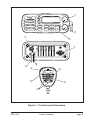
Figure 1. Controls and Connectors
SQL
VOL/PWR
16/9
NAV
SCAN
WX
CALL
/SET
H/L
16/9
INTREPID+
DISTRESS
PULL OPEN
q
w
e
t
y
u
i
o
!0
!1
r
!2

page 7 Owner’s Manual GX1270S
WX Key
Immediately recalls the previously selected NOAA weather channel
from any channel location.
Secondary use
1. Holding down the 16/9 key while pressing the WX key changes the
mode from USA to International or Canadian.
NOTE
If position is displayed, this icon will be hidden.
2. Holding down the WX and SCAN key while turning the power on resets
the microprocessor and erases scan channels from memory. This clears
the memory and establishes the factory-set defaults. For a list of these
defaults, see the section on Resetting the Transceiver’s Microprocessor.
SCAN Key
1. Starts and stops scanning of programmed channels.
2. If held while the UP or DOWN key on the mic are pressed or UP or
DOWN key on radio are pressed, the radio will show the channels in
scan memory. This function will not work if the unit is scanning.
NOTE
There is only one priority channel. The priority channel is marked with
P-CH on the LCD.
DISTRESS Key
Used to send a DSC Distress Call. To send the distress call see section
6.2, (Sending a Distress Call).
UP and DOWN Keys
The UP and DOWN keys are used to select a desired channel and to
select items in the DSC OPERATION and SETUP menus. The UP or
DOWN key on the microphone can also be used to select channels.
CALL/SET Key
The CALL/SET key functions as the enter key.
Secondary use
Press the CALL/SET key to access the DSC OPERATION menu. The
following DSC functions can be accessed from the DSC OPERATION menu;
INDIVIDUAL, GROUP, ALL SHIPS, TELEPHONE, STANDBY, CALL
WAIT, POS REQUEST and POS SEND.

GX1270S Owner’s Manual page 8
Press and hold the CALL/SET key to access the SETUP menu. The
following functions can be accessed in the SETUP menu; LAMP
ADJUST, CONTRAST, CH NAME, INDIV DIR, TELEPHONE
MEMORY ID, POS REPLY, SCRAMBLER, KEY BEEP, INDIV RING,
TIME SET, USER MMSI, GROUP MMSI, DSC SCAN.
H/L Key
Toggles between high and low power. When the H/L key is pressed
while the transceiver is on channel 13 or 67, the power will temporarily
switch from LO to HI power until the PTT is released. The H/L key does
not function on transmit inhibited and low power only channels.
NAV / IC Key
1. Pressing this key, when connected to the GPS receiver, the LCD
displays position data, Date, Time, SOG (Speed Over Ground) and
COG (Course Over Ground) from the GPS.
2. Press and hold down this key, when the optional RAM Mic
connected. Intercom operation will operate between radio and RAM
Mic.
r RAM MIC CONNECTOR
Connects the Remote Access Microphone (RAM MIC). Refer to
“section 8.0, (RAM MIC OPERATION).
t ACCESSORY CONNECTION CABLE
Connects the radio to a GPS, and an external speaker.
y DC INPUT CABLE
Connects the radio to a DC power supply of 13.8V
u ANTENNA JACK
Connects an antenna to the transceiver. Use a marine VHF antenna
with an impedance of 50 ohms.
i PTT (Push-To-Talk) SWITCH
Keys the transmitter when the transceiver is in radio mode. If the
transceiver is in the intercom operation mode, it activates the
microphone for the intercom.

page 9 Owner’s Manual GX1270S
o CLEAR VOICE NOISE-CANCELING SPEAKER MIC
Transmits the voice message with reduction of background noise.
!0 UP and DOWN KEYS
The UP and DOWN on the mic function the same as the UP and
DOWN key on the front panel of the transceiver.
!1 16/9 Key
Pressing the 16/9 key Immediately recalls channel 16 from any
location. Press and hold the 16/9 key to recall channel 9. Pressing the
16/9 key again revert the radio to the previous select channel.
!2 MICROPHONE SPEAKER
The same audio heard through internal radio speaker as heard through
microphone speaker.

GX1270S Owner’s Manual page 10
4 INSTALLATION
4.1 LOCATION
1. The radio can be mounted at any angle. Choose a mounting
location that:
• is far enough from any compass to avoid any deviation in compass
reading due to the speaker magnet
• provides accessibility to the front panel controls
• allows connection to a power source and an antenna
• has nearby space for installation of a microphone hanger
• the antenna must be mounted at least 3 feet from radio
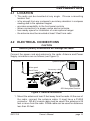
4.2 ELECTRICAL CONNECTIONS
CAUTION
Reverse polarity connections will damage the radio!
Connect the power cord and antenna to the radio. Antenna and Power
Supply connections are as follows (see Figure 2):
1. Mount the antenna at least 3 feet away from the radio. At the rear of
the radio, connect the antenna cable. It must have a PL259
connector. RG-8/U coaxial cable must be used if the antenna is 25
feet or more from the radio. RG58 cable can be used for distances
less than 25 feet.
Optional Speaker
Antenna
Water proof
Deck Outlet
Power Source
Black
Red
Fuse
Figure 2. General Installation
A
SQL
GPS Navigation Receiver
Accessory cable

page 11 Owner’s Manual GX1270S
2. Connect the red power wire to a 13.8 VDC ± 20% power source.
Connect the black power wire to a negative ground.
3. If an optional remote extension speaker is to be used, refer to
section 4.3 for connections.
4. It is advisable to have a Certified Marine Technician check the
power output and the standing wave ratio of the antenna after
installation.
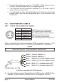
4.3 ACCESSORY CABLE
4.3.1 Cable pin number and signal
NMEA 0183 Version (1.5 to 2.3 ) Input Sentences:
GLL – Geographic Position–Longitude/Latitude
RMC – Recommended Minimum Specific GNSS Data
NMEA 0183 Version (2.3) Output Sentences:
DSC – Digital Selective Calling Information
DSE – Expanded Digital Selective Calling Information
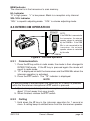
When connecting the external speaker, GPS navigation receiver, or PA
speaker strip off about 1 inch (2 cm) of the specified wire’s insulation.
NOTE
Never short wires. This may lead to malfunctions.
White: External speaker (+)
Yellow: External speaker (–)
Blue:
NMEA IN (+) from GPS navigation receiver
Green:
NMEA IN (–) from GPS navigation receiver
Brown:
NMEA OUT (–) to Standard Horizon GPS
#1
Gray:
NMEA OUT (+) to Standard Horizon GPS
#1
To external speaker and GPS receiver
To GX1270S
1
2
3
6
4
5
Pin number
Signal
1
External speaker (+)
2
External speaker (–)
3
NMEA IN (+)
4
NMEA IN (–)
5
NMEA OUT (+)
6
NMEA OUT (–)
#1: Connecting these wires to Standard Horizon GPS to show a DSC Position
Request, Position Send or Distress Call on the display of the GPS.

GX1270S Owner’s Manual page 12
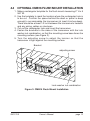
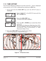
4.4 OPTIONAL CMB16 FLUSH MOUNT INSTALLATION
1. Make a rectangular template for the flush mount measuring 2" H x 5
5/8" W.
2. Use the template to mark the location where the rectangular hole is
to be cut. Confirm the space behind the dash or panel is deep
enough to accommodate the transceiver (at least 6 inches deep).
There should be at least 1/2 inch between the transceiver’s heatsink
and any wiring, cables or structures.
3. Cut out the rectangular hole and insert the transceiver.
4. Fasten the brackets to the sides of the transceiver with the lock
washer nut combination, so that the mounting screw base faces the
mounting surface (see Figure 3).
5. Turn the adjusting screw to adjust the tension so that the
transceiver is tight against the mounting surface.
Bracket
adjusting screw
Lock-washer nut combination
Figure 3. CMB16 Flush Mount Installation

page 13 Owner’s Manual GX1270S
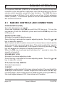
5 BASIC OPERATION
5.1 RECEPTION
1. After the transceiver has been installed, ensure that the power
supply and antenna are properly connected.
2. Press and hold the VOL/PWR knob until the radio turns on.
3. Turn the SQL knob fully counterclockwise. This state is known as
“squelch off”.
4. Turn up the volume until noise or audio from the speaker is at a
comfortable level.
5. Turn the SQL knob clockwise until the random noise disappears.
This state is known as the “squelch threshold.”
6. Press the UP or DOWN key to select the desired channel. Refer to
the channel chart in the OWNER’S MANUAL SUPPLEMENT for
available channels.
7. When a message is received, adjust the volume to the desired
listening level. The “BUSY” indicator in the LCD is displayed
indicating that the channel is being used.
5.2 TRANSMISSION
1. Perform steps 1 through 6 of RECEPTION.
2. Before transmitting, monitor the channel to ensure it is clear. THIS
IS AN FCC REQUIREMENT!
3. Press the PTT (push-to-talk) switch. The TX indicator on the LCD is
displayed.
4. Speak slowly and clearly into the microphone.
5. When the transmission is finished, release the PTT switch.
NOTE
This is a noise-canceling microphone. The oval slot on the top of
microphone should be positioned within 1 inch (2 cm) from the mouth
for optimum performance.
6. Refer to the OWNER’S MANUAL SUPPLEMENT for standard
transceiver operating procedures.

GX1270S Owner’s Manual page 14
5.3 TRANSMIT TIME - OUT TIMER (TOT)
When the PTT switch on the microphone is held down, transmit time is
limited to 5 minutes. This prevents unintentional transmissions. About 10
seconds before automatic transmitter shutdown, a warning beep will be
heard from the speaker(s). The transceiver will automatically go to receive
mode, even if the PTT switch is continually held down. Before transmitting
again, the PTT switch must first be released and then pressed again.
5.4 SIMPLEX/DUPLEX CHANNEL USE
Refer to the OWNER’S MANUAL SUPPLEMENT for instructions on use of
simplex and duplex channels.
NOTE
All channels are factory-programmed in accordance with FCC (USA),
Industry Canada (Canada), and International regulations. Mode of
operation cannot be altered from simplex to duplex or vice-versa.
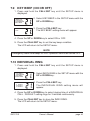
5.5 USA, CANADA, AND INTERNATIONAL MODE
1. To change the modes, hold the 16/9 key and press the WX key. The
mode changes from USA to International to Canadian with each
press of the WX key.
2. USA will be displayed on the LCD for USA mode, INTL will be
displayed for International mode, and CAN will be displayed for
Canadian mode.
3. Refer to the OWNERS MANUAL SUPPLEMENT for allocated
channels in each mode.

page 15 Owner’s Manual GX1270S
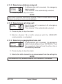
5.6 NOAA WEATHER CHANNELS
1. To receive a NOAA weather channel, press the WX key from any
channel. The transceiver will go to the last selected weather
channel.
2. Press the UP or DOWN key on the microphone to select a different
NOAA weather channel.
3. To exit from the NOAA weather channels, press the WX key. The
transceiver returns to the channel it was on prior to a weather
channel.
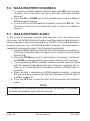
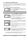
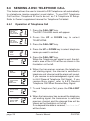
5.7 NOAA WEATHER ALERT
In the event of extreme weather disturbances, such as storms and
hurricanes, the NOAA (National Oceanic and Atmospheric Administration)
sends a weather alert accompanied by a 1050 Hz tone and subsequent
weather report on one of the NOAA weather channels. The transceiver is
capable of receiving this alert if the following is performed:
1. Program NOAA weather channels into the transceiver’s memory for
scanning. Follow the same procedure as for regular channels under
Section 5.8.
2. Press the SCAN key once to start memory scanning or hold down
the SCAN key during memory scanning to start priority scanning.
3. The programmed NOAA weather channels will be scanned along
with the regular-programmed channels. However, scanning will not
stop on a normal weather broadcast unless a NOAA alert is
received.
4. When an alert is received on a NOAA weather channel, scanning
will stop and the transceiver will emit a loud beep to alert the user of
a NOAA broadcast.
5. Press the WX key to stop the alert tone and receive the weather
report.
NOTE
If the WX key is not pressed the alert tone will be emitted for 5 minutes
and then the weather report will be received.

GX1270S Owner’s Manual page 16
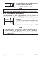
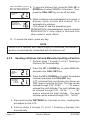
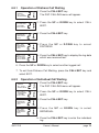
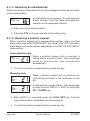
5.8 MEMORY SCANNING (M-SCAN)
NOTE
• During scanning, the dot matrix area of the LCD will show M-SCAN or
P-SCAN depending on the scan mode selected.
• If position is displayed this icon will be hidden.
1. Adjust the SQL knob until background noise disappears.
2. Select a desired channel to be scanned using the UP or DOWN key.
Press and hold the SCAN key, MEM will appear on the LCD which
programs the channel into the transceivers memory.
3. Repeat step 2 for all the desired channels to be scanned.
4. To DELETE a channel from the transceiver’s memory, press and
hold the SCAN key, MEM will disappear in the LCD.
5. To start scanning, press the SCAN key. Scanning will proceed from
the lowest to the highest programmed channel number and will stop
on a channel when a transmission is received.
6. The received channel number will blink during
busy stop.
7. To stop scanning, press the SCAN, 16/9, WX, or PTT key.
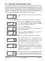
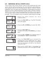
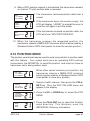
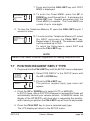
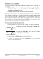
5.9 PRIORITY SCANNING (P-SCAN)
1. The priority channel is set to channel 16..
2. For priority scanning during M-SCAN, press and
hold the SCAN key, until P-SCAN appears in
the LCD. Scanning will proceed between the
memorized channels and the priority channel.
The priority channel will be scanned after each
programmed channel
CH. 16MEM CH. CH. 70MEM CH.CH. 70 CH. 16
(When DSC scaning
is available)
(When DSC scaning
is available)
BUSY HI USA
M–SCAN
VTS
A
MEM HI USA
P–SCAN CH16
A

page 17 Owner’s Manual GX1270S
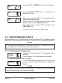
3. The scanning will be performed while receiving
the MEM CH (memorized channel).
4. To stop scanning, press the SCAN, 16/9, WX, or PTT key.
NOTE
Triple watch (T/W) means the radio is watching CH70 for DSC Calls.
Dual watch (D/W) means the radio is not watching CH70 for DSC Calls.
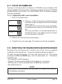
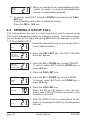
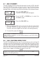
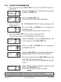
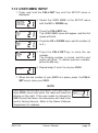
5.10 NAVIGATION INDICATION
The transceiver has the ability to display the time, SOG and COG date, as
well as the vessel’s position (LAT/LON), if connected to a GPS receiver.
1. Press the NAV key to display position
information.
If the GPS receiver receives no signal, the
display will as shown in the illustration on the
left.
2. To hide the position information, press the NAV
key.
NOTE
• The TIME OFFSET should be set to local time in the DSC/RADIO
setup mode when the radio is connected the GPS navigation
receiver. To adjust TIME OFFSET to your local time, refer to section
7.11 TIME OFFSET.
BUSY HI USA
T/W CH16
VTS
A
JUN15 8:45P
15 KT 160T
35
.
55. 000'N
A
138
.
28. 000'W
HI USA
INVALID
NO POSTION
DATA
A
Page is loading ...
Page is loading ...
Page is loading ...
Page is loading ...
Page is loading ...
Page is loading ...
Page is loading ...
Page is loading ...
Page is loading ...
Page is loading ...
Page is loading ...
Page is loading ...
Page is loading ...
Page is loading ...
Page is loading ...
Page is loading ...
Page is loading ...
Page is loading ...
Page is loading ...
Page is loading ...
Page is loading ...
Page is loading ...
Page is loading ...
Page is loading ...
Page is loading ...
Page is loading ...
Page is loading ...
Page is loading ...
Page is loading ...
Page is loading ...
Page is loading ...
Page is loading ...
Page is loading ...
Page is loading ...
Page is loading ...
Page is loading ...
Page is loading ...
Page is loading ...
Page is loading ...
Page is loading ...
Page is loading ...
Page is loading ...
Page is loading ...
Page is loading ...
Page is loading ...
Page is loading ...
Page is loading ...
Page is loading ...
Page is loading ...
Page is loading ...
-
 1
1
-
 2
2
-
 3
3
-
 4
4
-
 5
5
-
 6
6
-
 7
7
-
 8
8
-
 9
9
-
 10
10
-
 11
11
-
 12
12
-
 13
13
-
 14
14
-
 15
15
-
 16
16
-
 17
17
-
 18
18
-
 19
19
-
 20
20
-
 21
21
-
 22
22
-
 23
23
-
 24
24
-
 25
25
-
 26
26
-
 27
27
-
 28
28
-
 29
29
-
 30
30
-
 31
31
-
 32
32
-
 33
33
-
 34
34
-
 35
35
-
 36
36
-
 37
37
-
 38
38
-
 39
39
-
 40
40
-
 41
41
-
 42
42
-
 43
43
-
 44
44
-
 45
45
-
 46
46
-
 47
47
-
 48
48
-
 49
49
-
 50
50
-
 51
51
-
 52
52
-
 53
53
-
 54
54
-
 55
55
-
 56
56
-
 57
57
-
 58
58
-
 59
59
-
 60
60
-
 61
61
-
 62
62
-
 63
63
-
 64
64
-
 65
65
-
 66
66
-
 67
67
-
 68
68
-
 69
69
-
 70
70


Standard Horizon GX1270S Owner's manual
- Type
- Owner's manual
- This manual is also suitable for
Ask a question and I''ll find the answer in the document
Finding information in a document is now easier with AI
Related papers
-
Standard Horizon GX1265S Owner's manual
-
-
-
-
-
-
-
-
-
Other documents
-
RADIOLA JMC RT-2500 Owner's manual
-
 NASA SX 35 DSC Specification
-
 M-tech MT-500 Owner's manual
-
Lowrance electronic LVR-850 User manual
-
Furuno FM-8500 User manual
-
Alinco DR-MX15 User manual
-
-
-
Raymarine Ray48 User manual
-

