Page is loading ...

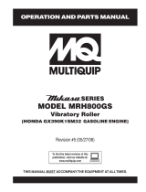
CV-SERIES
VIBRATOR MOTOR
OPERATION AND PARTS MANUAL
Revision #1 (06/13/07)
P/N 36686LUL
MODEL CV-1
MODEL CV-2
MODEL CV-2E
MODEL CV-3
MODEL CV-3E
THIS MANUAL MUST ACCOMPANY THE EQUIPMENT AT ALL TIMES.
To find the latest revision of this
publication, visit our website at:
www.multiquip.com

Engine exhaust and some of
its constituents, and some dust created
of California to cause cancer, birth
defects and other reproductive harm.
by power sanding, sawing, grinding,
drillingandotherconstructionactivities
contains chemicals known to the State
Some examples of these chemicals are:
Leadfromlead-basedpaints.
Crystallinesilicafrombricks.
Cementandothermasonryproducts.
Arsenicandchromiumfromchemically
treatedlumber.
Your risk from these exposures varies,
dependingonhowoftenyoudothistype
of work. To reduce your exposure to
these chemicals: work in aALWAYS
well ventilated area, and work with
approved safety equipment, such as
dust masks that are specially designed
to filter out microscopic particles.
CV-SERIES — PROPOSITION 65 WARNING

CV-SERIES • VIBRATOR MOTOR — PARTS AND OPERATION MANUAL — REV. #1 (06/13/07) — PAGE 3
Grinding/cutting/drilling of masonry, concrete, metal and
other materials with silica in their composition may give
off dust or mists containing crystalline silica. Silica is a
basic component of sand, quartz, brick clay, granite and
numerous other minerals and rocks. Repeated and/or
substantial inhalation of airborne crystalline silica can
cause serious or fatal respiratory diseases, including
silicosis. In addition, California and some other
authorities have listed respirable crystalline silica as a
substance known to cause cancer. When cutting such
materials, always follow the respiratory precautions
mentioned above.
WARNING
Grinding/cutting/drilling of masonry, concrete, metal and
other materials can generate dust, mists and fumes
containing chemicals known to cause serious or fatal
injury or illness, such as respiratory disease, cancer,
birth defects or other reproductive harm. If you are
unfamiliar with the risks associated with the particular
process and/or material being cut or the composition of
the tool being used, review the material safety data
sheet and/or consult your employer, the material
manufacturer/supplier, governmental agencies such as
OSHA and NIOSH and other sources on hazardous
materials. California and some other authorities, for
instance, have published lists of substances known to
cause cancer, reproductive toxicity, or other harmful
effects.
Control dust, mist and fumes at the source where
possible. In this regard use good work practices and
follow the recommendations of the manufacturers or
suppliers, OSHA/NIOSH, and occupational and trade
associations. Water should be used for dust
suppression when wet cutting is feasible. When the
hazards from inhalation of dust, mists and fumes cannot
be eliminated, the operator and any bystanders should
always wear a respirator approved by NIOSH/MSHA for
the materials being used.
WARNING
SILICOSIS WARNING RESPIRATORY HAZARDS
CV-SERIES — SILICOSIS/ RESPIRATORY WARNINGS

PAGE 4 — STR 31V
CV-SERIES • VIBRATOR MOTOR — PARTS AND OPERATION MANUAL — REV. #1 (06/13/07) — PAGE 4
CV-SERIES — TABLE OF CONTENTS
Specifications and part numbers
are subject to change without
notice.
NOTE
MQ MULTIQUIP — CV-SERIES
VIBRATOR MOTOR
Proposition 65 Warning ............................................. 2
Silicosis/Respiratory Warnings .................................. 3
Table of Contents ...................................................... 4
Parts Ordering Procedures ....................................... 5
Safety Message Alert Symbols ................................. 6
Rules For Safe Operation ...................................... 7-9
Specifications .......................................................... 10
Decals ..................................................................... 11
Preparation ............................................................. 12
Operation ................................................................ 13
Maintenance ...................................................... 14-16
Troubleshooting ...................................................... 17
Vibrator Motor Housing ...................................... 18-19
Vibrator Motor Assembly ................................... 20-21
Terms and Conditions of Sale ................................. 22

CV-SERIES • VIBRATOR MOTOR — PARTS AND OPERATION MANUAL — REV. #1 (06/13/07) — PAGE 5
PARTS ORDERING PROCEDURES
www.multiquip.com
Ordering parts has never been easier!
Choose from three easy options:
WE ACCEPT ALL MAJOR CREDIT CARDS!
When ordering parts, please supply:
❒❒
❒❒
❒
Dealer Account Number
❒❒
❒❒
❒
Dealer Name and Address
❒❒
❒❒
❒
Shipping Address (if different than billing address)
❒❒
❒❒
❒
Return Fax Number
❒❒
❒❒
❒
Applicable Model Number
❒❒
❒❒
❒
Quantity, Part Number and Description of Each Part
❒❒
❒❒
❒
Specify Preferred Method of Shipment:
✓
UPS/Fed Ex
✓ DHL
■
Priority One
✓
Tr u ck
■
Ground
■ Next Day
■
Second/Third Day
All orders are treated as
Standard Orders
and will ship the same day if received prior
to 3PM PST.
If you have an MQ Account, to obtain a
Username and Password, E-mail us at:
To obtain an MQ Account, contact your
District Sales Manager for more information.
Order via Internet (Dealers Only):
Order parts on-line using Multiquip’s SmartEquip website!
■
View Parts Diagrams
■
Order Parts
■
Print Specification Information
Note: Discounts Are Subject To Change
Goto www.multiquip.com and click on
Order Parts
to log in and save!
Use the
internet
and qualify for a 5% Discount
on
Standard orders
for all orders which include
complete part numbers.*
Order via Fax (Dealers Only):
All customers are welcome to order parts via Fax.
Domestic (US) Customers dial:
1-800-6-PARTS-7 (800-672-7877)
Fax
your order in and qualify for a 2% Discount
on
Standard orders
for all orders which include
complete part numbers.*
Order via Phone:
Domestic (US) Dealers Call:
1-800-427-1244
Best Deal!
International Customers
should contact
their local Multiquip Representatives for
Parts Ordering information.
Non-Dealer Customers:
Contact your local Multiquip Dealer for
parts or call 800-427-1244 for help in
locating a dealer near you.
Note: Discounts Are Subject To Change
NOTE
Effective: January 1
st
, 2006

PAGE 6 — STR 31V
CV-SERIES • VIBRATOR MOTOR — PARTS AND OPERATION MANUAL — REV. #1 (06/13/07) — PAGE 6
Accidental Starting
ALWAYS wear approved eye and hearing
protection.
Sight and Hearing hazard
CV-SERIES — SAFETY MESSAGE ALERT SYMBOLS
Accidental starts can cause severe injury or death. ALWAYS
place the ON/OFF switch in the OFF position when the Vibrator
Motor is not in use.
HAZARD SYMBOLS
Gasoline is extremely flammable, and its
vapors can cause an explosion if ignited. DO
NOT start the Vibrator Motor near spilled fuel
or combustible fluids. NEVER operate the
Vibrator Motor in an explosive atmosphere
or near combustible materials. An explosion
or fire could result causing severe bodily
harm or even death.
Explosive Fuel
Burn Hazards
Engine components can generate extreme heat.
To prevent burns, DO NOT touch these areas
while the engine is running or immediately after
operations. NEVER operate the engine with
heat shields or heat guards removed.
Rotating Parts
NEVER operate equipment with covers, or
guards removed. Keep
fingers, hands
,
hair
and
clothing
away from all moving parts to
prevent injury.
Safety precautions should be followed at all times when
operating this equipment. Failure to read, understand and
comply with the Safety Messages and Operating Instructions
could result in injury to yourself and others.
FOR YOUR SAFETY AND THE SAFETY OF OTHERS!
Before using this Vibrator Motor, ensure that the operating
individual has read, understands, and complies with all
instructions in this manual.
SAFETY MESSAGE ALERT SYMBOLS
The three (3) Safety Messages shown below will inform you
about potential hazards that could injure you or others. The
Safety Messages specifically address the level of exposure to
the operator, and are preceded by one of three words: DANGER,
WARNING, or CAUTION.
You WILL be
KILLED
or
SERIOUSLY INJURED
if you DO NOT follow these directions.
You CAN be KILLED or
SERIOUSLY INJURED
if
you DO NOT follow these directions.
You CAN be
INJURED
if you DO NOT follow
these directions.
CAUTICAUTI
CAUTICAUTI
CAUTION
DANGERDANGER
DANGERDANGER
DANGER
WARNINGWARNING
WARNINGWARNING
WARNING
Potential hazards associated with vibrator motor operation will
be referenced with Hazard Symbols which appear throughout
this manual, and will be referenced in conjunction with Safety
Message Alert Symbols.
This Operation Manual has been
developed to provide instructions for the
safe and efficient operation of the CV -
Series Vibrator Motor.

CV-SERIES • VIBRATOR MOTOR — PARTS AND OPERATION MANUAL — REV. #1 (06/13/07) — PAGE 7
CV-SERIES — RULES FOR SAFE OPERATION
GENERAL SAFETY RULES
■
DO NOT operate or service this
equipment before you read, understand,
and comply with all safety messages in
this manual. The manual must be kept
available and accessible to the operator.
RULES FOR SAFE OPERATION
■
ALWAYS check the vibrator motor for loosened hardware
such as nuts and bolts before starting.
■
Replace nameplate, operation and safety decals when they
become difficult to read.
■
NEVER use accessories or attachments which are not
recommended by the manufacturer for this equipment.
Damage to the equipment and/or injury to user may result.
WARNINGWARNING
WARNINGWARNING
WARNING
Failure to follow instructions in this manual may lead to serious
injury or even death! This equipment is to be operated by
trained and qualified personnel only! This equipment is for
industrial use only.
■
NEVER operate a vibrator motor while under the influence of
drugs, alcohol, or medications that may impair the senses or
reactions.
■
NEVER use this machine for any purpose other than those
described in this manual.
■
This equipment should not be operated by persons under
the minimum statutory age limit.
The following safety guidelines should always be used when
operating the CV-SERIES Vibrator Motor.
VIBRATOR MOTOR OPERATION SAFETY RULES
■
Dress properly. Wear appropriate clothing and protective
safety equipment. Wear clothing that will not likely become
caught in the equipment or snag on the forms. Eye, hand,
hearing, and foot safety equipment is required.
■
Manufacturer does not assume responsibility for any accident
due to equipment modifications. Unauthorized equipment
modification will void all warranties. Any modification which
could lead to a change in the original characteristics of the
machine should be made only by the manufacturer who shall
confirm that the machine is in conformity with appropriate
safety regulations.
■
Keep untrained personnel away. DO NOT let visitors contact
the vibrator unit. All visitors should be kept away from the
work area.
■
Keep work area well lit.
■
Keep work area clean and well organized. A cluttered area
invites injuries.
■
ALWAYS clear the work area of any debris, tools, etc. that
would constitute a hazard while the vibrator motor is in
operation.
■
ALWAYS be sure the operator is familiar with proper safety
precautions and operations techniques before using vibrator
motor.
■
DO NOT overreach. Keep proper footing and balance at all
times.
■
Secure forms. Make sure the form work is well made and
braced to withstand the stresses made by vibration.
■
Keep vibrator motor clean for better and safer operation.
■
Inspect motor cord periodically and if damaged, have it
repaired by an authorized service facility.
■
Before each use
ALWAYS
check the motor to make certain
there are no damaged parts, and that all parts function
properly, (examples: switch, cord housing). If any damage or
malfunctioning parts are found, have them repaired or
replaced by an authorized service facility.
■
Use only factory authorized identical
replacement parts
.
■
Always observe all applicable compulsory regulations
relevant to environmental protection, especially, fuel storage,
the handling of hazardous substances, and the wearing of
protective clothing and equipment. Instruct the user as
necessary, or, as the user, request this information and
training.

PAGE 8 — STR 31V
CV-SERIES • VIBRATOR MOTOR — PARTS AND OPERATION MANUAL — REV. #1 (06/13/07) — PAGE 8
CV-SERIES — RULES FOR SAFE OPERATION
■
ALWAYS keep clear of
rotating
or
moving parts
while
operating the vibrator motor.
■
NEVER leave the machine
unattended
while running.
■
ALWAYS turn the motor off and unplug the power cord before
performing service or maintenance functions.
■
DO NOT yank the cord to disconnect it from the receptacle.
Grasp the plug itself to disconnect it.
■
Allow the vibrator motor to cool before servicing.
Contact with
hot!
components can cause
serious burns.
■
NEVER operate the vibrator motor in
an explosive atmosphere where
fumes are present, or near
combustible materials. An explosion or
fire could result in severe
bodily harm
or even death.
■
ALWAYS disconnect the motor from the power source when
not in use, before servicing, and when changing flexible
shafting and vibrator heads.
■
Before plugging the motor into a power source, ALWAYS
remove any wrenches or other tools from the motor, shaft,
and head that were used for assembly.
■
NEVER carry the motor by the cord. Use the carrying frame.
■
Keep the cord from heat, oil, and sharp objects.
■
DO NOT overload the motor. It will do a better and safer job
at the rate for which it was designed.
■
DO NOT force the motor and head to do the job of a larger
motor and head.
■
DO NOT expose vibrator motor to rain.
■
DO NOT use vibrator motor in damp or wet locations without
proper electrical circuits.
■
Be sure switch is in the "OFF" position before plugging the
motor into a power source.
■
DO NOT carry plugged-in motor with finger on the switch.
■
Store idle vibrator motor. When not in use, motor should be
stored in a dry, safe storage area.
■
NEVER use the motor with a defective switch. If the switch
does not turn the motor "ON" or "OFF", have it replaced before
using the motor.
VIBRATOR MOTOR ELECTRICAL SAFETY RULES
1. Know your concrete vibrator. Read this instruction manual.
Learn the vibrator's applications, limitations, and specific
potential hazards peculiar to this tool.
2. Guard against electrical shock.
3. Prevent body contact with grounded surfaces. (For example:
pipes, reinforcing bar, etc.)
WARNINGWARNING
WARNINGWARNING
WARNING
When using electric tools, basic
safety precautions MUST be
followed to reduce the risk of fire
and electric shock.
■
Use a protection wiring device, such as a Ground Fault
Circuit Interrupter, for the protection of personnel.
■
This concrete vibrator motor is equipped with a 3-conductor
cord, and a 3-prong grounding type plug to fit the proper
grounding type receptacle. The green conductor in the cord
is the ground wire. NEVER connect the green wire to a live
terminal. See (Figure 1) for proper grounding methods.
Figure 1. Grounding Methods (Typical)
1. Grounding Pin
2. Metal Screw
3. Adapter
4. Grounding Means
2
4
1
3
1

CV-SERIES • VIBRATOR MOTOR — PARTS AND OPERATION MANUAL — REV. #1 (06/13/07) — PAGE 9
CV-SERIES — RULES FOR SAFE OPERATION
ALWAYS use a grounded 3-wire extension cord that has a
3-prong grounding plug, and a 3-pole receptacle that
accepts the plug on the concrete vibrator motor. DO NOT
REMOVE THE GROUNDING PIN FROM THE PLUG!
WARNINGWARNING
WARNINGWARNING
WARNING
WARNINGWARNING
WARNINGWARNING
WARNING
MAKE CERTAIN the motor is connected to a GROUND
FAULT CIRCUIT INTERRUPTER to protect the operator
from possible electric shock.
4. Use of extension cords.
■
MAKE CERTAIN the power cord/extension cord is free
from damage, and that the grounding circuit is
operational. Repair or replace all damaged cords and
grounding units.
■
When extending the cord, DO NOT submerge the
connection in water. Avoid the possiblility of electric
shock by ALWAYS making water-tight connections.
■
Use only extension cords that are intended for outdoor
use and so marked.
■
Use only the gauge wire and length of cord
recommended for the motor size. If in doubt, go to the
next heavier gauge. (The smaller the gauge number,
the heavier the cord.)
■
See (Table 1) for recommended extension cord sizes.
seziSdroCnoisnetxE.1ELBAT
erepmA
gnitaR
egnaR
stloV teeFnidroCfohtgneL
V511 .tF52 .tF05 .tF001 .tF051 .tF002 .tF052
V032 .tF05 .tF001 .tF002 .tF003 .tF004 .tF005
2-0 81 81 81 61 61 41
3-2 81 81 61 41 41 21
4-3 81 81 61 41 21 21
5-4 81 81 41 21 21 01
6-5 81 61 41 21 01 01
8-6 81 61 21 01 01 8
01-8 81 41 21 01 8 8
21-01 61 41 01 8 8 6
41-21 61 21 01 8 6 6
61-41 61 21 01 8 6 6
81-61 41 21 8 8 6 4
02-81 41 21 8 6 6 4
CAUTIONCAUTION
CAUTIONCAUTION
CAUTION
Emergencies
■
ALWAYS know the location of the
nearest
first aid kit
.
■
Know the phone numbers of the nearest
ambulance
,
doctor
and
fire department
. Ensure
that a phone or radio is readily available at the
jobsite. If this is not possible, know the location of
the nearest phone. This information will be
invaluable in the event of an emergency.
■
ALWAYS know the location of
the nearest
fire extinguisher
.
Use of an extension cord with a wire gauge smaller than, or
length longer than that stated previously could result in
reduced motor performance and/or damage to the motor or
extension cord due to overheating.

PAGE 10 — STR 31V
CV-SERIES • VIBRATOR MOTOR — PARTS AND OPERATION MANUAL — REV. #1 (06/13/07) — PAGE 10
CV-SERIES— SPECIFICATIONS (VIBRATOR MOTOR)
Figure 2. Dimensions
SNOITACIFICEPS.2ELBAT
ledoM 1-VC E2-VC/2-VC E3-VC/3-VC
rewopesroH )Wk647.0(PH1 )Wk294.1(PH2 )Wk832.2(PH3
htgneL )mm343("5.31 )mm343("5.31 )mm343("5.31
htdiW )mm52.222("57.8 )mm52.222("57.8 )mm52.222("57.8
thgieH )mm58.691("57.7 )mm58.691("57.7 )mm58.691("57.7
thgieW )g5.9894(.SBL11 )g9.9665(.SBL5.21 )g5.3216(.SBL5.31
)daoLoN(MPR MPR000,22 MPR000,22 MPR000,22
stloV CAV511 CAV511 CAV032 CAV511 CAV032
spmA A01 A51 A5.7 A02 A01
ztreH zH06/05 zH06/05 zH06/05

CV-SERIES • VIBRATOR MOTOR — PARTS AND OPERATION MANUAL — REV. #1 (06/13/07) — PAGE 11
CV-SERIES — OPERATION AND SAFETY DECALS
Machine Safety Decals
The CV-SERIES VIBRATOR MOTOR is equipped with a number of operation and safety decals. These decals are provided for
operator safety and maintenance information. Should any of these decals become unreadable, replacements can be obtained from
your dealer.
Figure 3. Decals
P/N 00100-44
P/N 36676
P/N 00100-46
CONTACT SERVICE DEPARTMENT
NC.
00100-57LUL
00100-59LUL
00100-61LUL
00100-62LUL
00100-63LUL

PAGE 12 — STR 31V
CV-SERIES • VIBRATOR MOTOR — PARTS AND OPERATION MANUAL — REV. #1 (06/13/07) — PAGE 12
CV-SERIES — PREPARATION AND OPERATION
1. The vibrator motor, flexible shafting, and heads are shipped
from the factory ready to use. Connect per instruction
bulletins.
2. Use only the combination of flexible shafting and heads
shown below in Table 3.
Before using your Vibrator Motor, read and
fully understand all of the safety and
operating instructions not only for the motor,
but also for the flexible shafting and the head
that will be used with the motor.
3. To connect the 314V or 382V flexible shafting to the vibrator
motor see illustration (Figure 4).
MAKE CERTAIN the motor is disconnected from the power
source and the switch is in the "OFF" position.
If the shaft begins to helix (buckle) excessively during
operation, stop and investigate. This is an indication of an
overload condition.
The vibrator head is cooled by the concrete. Operation of
the vibrator head in air longer than 2 minutes at a time will
cause overheating of the bearings which will result in
premature head failure.
Visually inspect the air intake and exhaust frequently to make
sure the motor has sufficient air for cooling.
WARNINGWARNING
WARNINGWARNING
WARNING
CAUTIONCAUTION
CAUTIONCAUTION
CAUTION
CAUTIONCAUTION
CAUTIONCAUTION
CAUTION
CAUTIONCAUTION
CAUTIONCAUTION
CAUTION
Figure 4. Motor-to-Shaft Connection
seziStfahS.3elbaT
LEDOM TFAHS EZISDAEH
TFAHS.XAM
HTGNEL
1-AVS V413
009
0001
0031
.TF12
2-AVS V283
0041
0071
.TF82
0012 .TF12
3-AVS V283
0041
0071
0012
0062
.TF53
1
2
3
4
6
5
1. Lock Assembly
2. Shaft Coupling Quick Disconnect
3. Spindle Shaft
4. Core Fitting
5. Motor
6. Drive Coupler Quick Disconnect
4. Slide the core out of the casing far enough to thread the
spindle (Item 3 Fig. 4) into the core fitting and tighten. A pair
of pliers and a wrench can be used to tighten the connection.
It is important that this connection is tight. If it is not, the
torque of the motor plus the load of the head will jam the two
fittings together making it extremely hard to loosen them for
disassembly.
5. Thread the shaft coupling (Item 2 Fig. 4) into the casing
ferrule and tighten.
6. Pull up on the lock pin and slide the shaft assembly into the
front motor bearing housing and release the lock pin. Give
the shaft assembly a twist to make sure that the lock pin is
seated in the lock groove of the shaft coupling.
7. Clean the mating parts threads with Locquic Primer "T".
Allow to dry several minutes before applying a ring of Loctite
No. 271 or equivalent to the middle of the casing threads.
Screw the head tightly to the casing and wait 1 hour before
using. Threads are
left-hand
; turn
counter-clockwise
to
tighten.

CV-SERIES • VIBRATOR MOTOR — PARTS AND OPERATION MANUAL — REV. #1 (06/13/07) — PAGE 13
CV-SERIES — OPERATION
CV-Series Vibrator Motor Familiarization
This
VIBRATOR MOTOR
is designed for the
compaction
of
concrete by removal of air pockets and voids.
The action of vibration is to set the particles in the fresh concrete
in motion, thereby reducing the friction between the particles
and giving the mixture the mobile quality of a thick fluid so gravity
and the displacement of entrapped air will cause it to settle easily
into place.
By consolidating the concrete quickly, "stiffer" or "drier" mixes
can be poured than would otherwise be possible. It has been
proven that (up to a point) the drier the concrete, (that is, the less
water in it), the better the quality throughout and the greater the
strength.
Drier mixes also make the concrete more water tight, increase
resistance to weathering, and create a better bond between
concrete and reinforcement. Because vibration causes much of
the entrapped air in the concrete to rise to the surface,
honeycombing is prevented. Vibration also eliminates most of
the air pockets between the concrete and the vertical forms.
CV-SERIES VIBRATOR MOTOR OPERATION
Read
all the safety instructions carefully. Safety instructions will
be found throughout this manual and on the Vibrator Motor. Keep
all safety information in good, readable condition.
1. Make certain that the flexible shaft is properly attached to
the motor and the head to the flexible shaft.
2. Use the flexible shaft in as straight a position as possible.
3. DO NOT bend the flexible shaft sharply at any point. Sharp
bends may cause a permanent kink, requiring early
replacement of the flexible shaft.
4. With the vibrator motor properly
plugged into the correct power source,
turn the ON/OFF switch to the "ON"
position and proceed to insert the
vibrator into the concrete.
5. The concrete is normally placed in the forms in layers about
12 to 18 inches thick in a manner which forms a fairly level
surface. The vibrator head is inserted vertically into the top
of the pile
.
6. DO NOT insert the head into the side of the pile to make the
concrete flow as this practice can cause segregation of the
aggregate from the mortar. When the surface has become
fairly level, the head the should be immersed and generally
moved in the pattern shown in Figure 5.
Figure 5. Compaction Coverage
with 50% Radial Overlap
7. Immerse the head for 5 to 10 seconds, (until air stops rising),
and then withdraw it slowly to let the concrete fill the void left
by the head.
8. The head shoud be completely below the surface when
vibrating to keep the head cool.
9. When vibrating a thin horizontal slab, the head can be used
in a horizontal position.
egarevoCnoitcapmoC.4elbaT
daeH 009 0001 0031 0041 0071 0012 0062
noisnemiD-P "4 "2/1-5 "8 "8 "21 "41 "81

PAGE 14 — STR 31V
CV-SERIES • VIBRATOR MOTOR — PARTS AND OPERATION MANUAL — REV. #1 (06/13/07) — PAGE 14
CAUTIONCAUTION
CAUTIONCAUTION
CAUTION
NOTE
CV-SERIES — MAINTENANCE
MAINTENANCE
Before performing any maintenance on this unit, ALWAYS
MAKE CERTAIN that the switch is in the "OFF" position
and the power cord is disconnected from the power source.
This is a universal motor and it will run at approximately its rated
speed if the motor and its attached equipment are properly
operated and maintained.
9. Vibrator heads should be inspected and relubricated every
100 hours of operation. Follow the instructions for vibrator
heads.
Heat should be used to break down
the threadlock (loctite) while you
unthread the head from the shaft. This
will help prevent damage to the
threads.
Bronze Wear Bushing Replacement
Refer to Figure 7 and the following steps for removal and
replacement of the bronze wear bushing.
1
2
5
6
7
8
4
3
1. Slotted Spring Pin
2. Quick Disconnect Knob
3. Spring Housing
4. Compression Spring
5. Lock Pin
6. Output Endbell Shaft
7. Bronze Wear Bushing
8. Shaft Coupling
Figure 7. Bronze Wear Bushing
1. If installed, remove head assembly and shaft coupling (item
8, Figure 7).
2. Remove pin (item 1, Figure 7) using hammer and punch of
appropriate size.
3. Once the pin is removed, the knob, spring and lock pin can
easily be removed. (items 2, 4, and 5)
1. Have repair work performed by an authorized service
facility, using identical or manufacturer approved
replacement parts.
2. This motor uses sealed bearings and does not require
lubrication.
3. Visually inspect the motor daily before use for defective or
missing parts, and have repairs made before use.
A
4. Inspect brushes frequently
and replace when they
become worn to a length of
3/8". (See Length A in
Figure 6).
Figure 6. Brush Length
5. Keep air inlet and air exit louvers clean and free of concrete
and debris. Failure to do so will result in rapid motor
overheating and parts failure.
6. Clean air filter as needed. If unit is used in high dust areas,
filter will have to be cleaned more often.
7. Use a screw driver to tighten brush caps. DO NOT
OVERTIGHTEN. The brush cap must be tight enough that
the brush holder does not move.
8. The 314V and 382V flexible shafts require cleaning and
relubrication every 100 hours of operation. Refer to flexible
shafting operating instructions for maintenance instructions.

CV-SERIES • VIBRATOR MOTOR — PARTS AND OPERATION MANUAL — REV. #1 (06/13/07) — PAGE 15
4. Using channel lock style pliers with soft jaws, unscrew the
spring housing (item 3). Heat may need to be applied to
break down the old threadlock to prevent damage to the
threads on the spring housing.
5. After the spring housing is removed, use a 3-jaw bearing
puller to remove the bronze wear bushing, (item 7).
6. To install a new bronze wear bushing, first align the hole in
the new bushing with the spring housing hole. Press the
bushing straight and evenly into place using a block of
wood or soft aluminum and a mallet. Bushing should be
flush with the end of the shaft when fully seated.
7. Clean all old threadlock from the spring housing and apply
new threadlock (Loctite blue 242 or equivalent).
8. Screw the spring housing firmly into place using channel
lock style pliers with soft jaws.
9. Reinstall the lock pin, spring and knob and secure with pin.
10. Verifiy the Quick Disconnect Knob operates freely and
snaps back into position. If the knob stays in the up position
there is binding occurring between the knob, spring, or
lock pin.
Motor Reassembly
Refer to Figure 8 or the Vibrator Motor Assembly illustration on
page 22 when performing the following steps.
1. Place the Brush Endbell (item 1, Figure 8) on work surface
with bearing pocket up.
2. Place two plastic insulators (items 2) in the holes on the
endbell.
3. Slide the Field Assembly (item 4), with the leads toward
the endbell, into place ensuring the plastic insulators
engage into the field holes.
4. Plug the brush flag leads (see Figure 9, Field Orientation)
into the top of the brush holders toward the output shaft
end. (See Figure 10).
5. Install the Armature/bearings Assembly (item 5) and Wave
Spring (item 3) through the Field and into the endbell
bearing pocket.
6. Place the remaining two plastic insulators (items 6) into the
holes of the Output Endbell (item 7).
If the motor required disassembly for servicing, reinstalling the
assembly back into the case will be much easier if all internal
components are reassembled as a unit first.
1. Brush Endbell
2. Plastic Insulator
3. Wave Loading Spring
4. Field Assembly
5. Armature & Bearing Assembly
6. Plastic Insulator
7. Output Endbell
8. Lock Washer
9. Screw
Figure 8. Motor Assembly
1
2
2
3
4
5
6
6
7
8
9
CV-SERIES — MAINTENANCE

PAGE 16 — STR 31V
CV-SERIES • VIBRATOR MOTOR — PARTS AND OPERATION MANUAL — REV. #1 (06/13/07) — PAGE 16
2
3
4
5
1
7. Slide the Output Endbell (item 7) down onto the Armature/
Bearing Assembly (item 5) so the bearing engages the
bearing pocket of the endbell and insulators seat properly
on the Field.
8. Install the lockwashers and long screws through both
endbells as shown and torque to 50-70 in. lbs. (5.65 N-m to
7.91 N-m).
9. Place the motor assembly into the plastic housing half that
has the threaded inserts. (item 1 Figure 11)
Field Orientation (Figure 9) (when viewed from the rear of
the motor)
CV-SERIES — MAINTENANCE
1. Lead to Switch
2. Lead to Brush Holder (Right Housing)
3. Lead to Brush Holder (Left Housing)
4. Lead to Switch
Figure 9. Field Orientation
Figure 11. Powercord hookup
Figure 10. Brush Leads
4
1
2
3
1. Plastic Housing Half (with inserts)
2. Ground Wire
3. Powercord Leads
4. Switch Plate Terminals
5. Motor Power Leads
15. Install housing screws and lockwashers shown in
illustration. Torque screws to 30-50 in-lbs, (3.39 N-m to
5.65 N-m).
16. Assemble the rubber TPR end caps and extruded tube
handles onto plastic housing assembly using screws and
washers shown in illustration.
10. Plug the Motor Power Leads (Items 5) to the spade
terminals of the Power Switch Terminal (item 4) shown in
Figure 11. Tuck the leads out of the way so they will not rub
on the rotating armature assembly and to prevent them
from getting pinched between the plastic housing halves.
11. Plug the Powercord Leads (items 3) to the Power Switch
Terminal as shown in Figure 11.
12. Attach Ground Wire (item 2) from powercord to rear of brush
endbell using screw and star washer.
13. Fit powercord into slot in housing half and place switch
plate, filter and plastic filter cover into slot on housing half.
Use illustration on page 20 for reference.
14. Assemble top plastic housing half (without the inserts) to
the bottom plastic housing half and snap together. (the lip
around the housing should "pop" as it aligns).

CV-SERIES • VIBRATOR MOTOR — PARTS AND OPERATION MANUAL — REV. #1 (06/13/07) — PAGE 17
CV-SERIES— TROUBLESHOOTING
GNITOOHSELBUORT.5ELBAT
MOTPMYS MELBORPELBISSOP NOITULOS
.tratstonseodrotoM
.rotomotrewopoN
eromroenO.)erar(hctiwstuotnruB
.neposnoitcennoclanretni
noisnetxeyfireV.teltuoreporpotnideggulpsitinuyfireV
.dehcniprotuctoneradnanideggulpylreporperasdroc
roh
ctiwsniamkcehc(.teltuotaelbaliavasirewopyfireV
).rekaerb
.dedeensasnoitcennocetelpmocroecalpeR
taestonodsevlahgnisuoH
ylreporprehtegot
.eriwdehcniP
detaestonrevoCretliFroetalPhctiwS
.ylreporp
.ylreporpdetaestontemmorGdroCrewoP
ottonNIATRECEKAM.seriwtsujdaotrevirdwercsesU
.seriwehtnonoitalusniehtegamad
.tolsgnisuoHniylreporpetalPhctiwStaeS
.tolsgnisuoHnitemmorgtaeS
morfesiongnilworg/gnillttaR
.aeragnisuohforaer
.eruliafgniraebraeR .gniraebecalpeR
morfesiongnilworg/gnilttaR
.aeragnisuohdrawrof
.relpuocnroW
.eruliafgniraebdrawroF
yawaseogesionfI.norotomnrutdnarelpuoctcennocsiD
.gniraebdrawrofkcehc,sniameresionfI.relpuocecalper
.gniraebecalpeR

PAGE 18 — STR 31V
CV-SERIES • VIBRATOR MOTOR — PARTS AND OPERATION MANUAL — REV. #1 (06/13/07) — PAGE 18
CV-SERIES — VIBRATOR MOTOR HOUSING ASSY.
VIBRATOR MOTOR HOUSING ASSY.

CV-SERIES • VIBRATOR MOTOR — PARTS AND OPERATION MANUAL — REV. #1 (06/13/07) — PAGE 19
CV-SERIES — VIBRATOR MOTOR HOUSING ASSY.
VIBRATOR MOTOR HOUSING ASSY.
NO. PART NO. PART NAME QTY. REMARKS
1 50125-03 END CAP, RUBBER 2
2 50125-07 HOUSING, PLASTIC WITH INSERTS 1
3 50125-08 HOUSING, PLASTIC WITHOUT INSERTS 1
4 52003-04 WASHER, FLAT 1/4" 12
5 52003-10 WASHER, LOCK M5 8
6 53701-01 SCREW, PAN HEAD M5 X 40MM 8
7 53701-02 SCREW, M6 X 1 X 16MM 6
8 57001-04 CAP, BRUSH ACCESS 2
9 65001-21 HANDLE TUBE EXTRUSION 3
10 00100-46 DECAL, SAFETY ................................................... 1 ....... SAFETY ITEM
11 8200-002 COVER, PLASTIC FILTER ASSY. 1
12 8200-003 SWITCH PLATE ASSY. 1
13 00100-44 DECAL, WARNING ................................................. 1 ....... SAFETY ITEM
14A 8006-010 POWER CORD, 3HP 115V NEMA L5-20P ............. 1 ....... REPLACES 44000-08
14B 8006-011 POWER CORD, 1HP/2HP 115V NEMA 5-15P ....... 1 ....... REPLACES 44000-09
14C 8006-012 POWER CORD, 2HP/3HP 230V NEMA 6-15P ....... 1 ....... REPLACES 44000-10
15 00100-57LUL DECAL, CV-1 115V 2
15 00100-59LUL DECAL, CV-2 115V 2
15 00100-61LUL DECAL, CV-2 230V 2
15 00100-62LUL DECAL, CV-3 115V 2
15 00100-63LUL DECAL, CV-3 230V 2
16 50000-03 AIR FILTER 1
17 TAG, SERIAL NUMBER ......................................... 1 ....... CONTACT SALES DEPT.
18 CS-1 CARRYING STRAP ............................................... 1 ....... OPTIONAL EQUIPMENT
19 7196K34 PLUG W/O CORD 5-20P ........................................ 1 ....... CV3 ONLY, OPTIONAL

PAGE 20 — STR 31V
CV-SERIES • VIBRATOR MOTOR — PARTS AND OPERATION MANUAL — REV. #1 (06/13/07) — PAGE 20
CV-SERIES — VIBRATOR MOTOR ASSY.
VIBRATOR MOTOR ASSY.
/