Weil-McLain LGB-8 User manual

Type
User manual
Part Number 550-141-797/0798
Contents
I. New installation ........... 2
II. Existing installation ..... 4
III. Gas piping ..................... 5
IV. Wiring ............................ 5
Sequence of operation ..... 8
Wiring procedure .............. 8
V. Operating instructions . 9
VI. Parts list – U.S. ........... 10
VII.Parts list – Canadian ... 11
Indicates presence of hazards that can cause severe personal injury, death or
substantial property damage.
Indicates special instructions on installation, operation or maintenance that
are important but not related to personal injury or property damage.
This Control Supplement must only be used by a qualified installer/service
technician. Read these instructions completely before beginning the
installation. Failure to follow these instructions can cause severe personal
injury, death or substantial property damage.
These terms are used throughout this
manual to bring attention to the
presence of hazards of various risk
levels or to important information
concerning the life of the product.
LGB
Gas–fired boiler
Universal Control System
U.S. and Canada
Control Supplement
Series 2Propane gas
Part Number 550-141-797/07982
LGB-6 to LGB-23 Series 2 – Control Supplement
New installationI
1. Remove all burners from base box assembly. Remove 3.95 mm natural gas main burner
orifices in manifold. Install 2.40 mm propane gas main burner orifices. Use pipe dope
sparingly only on male ends. Use pipe dope compatible with propane gases. Do not
overtighten orifices.
2. Install pilot burners and flame sensor(s). See Figures 1 and 2 (page 3). Follow Table 1 for
electronic pilot burner (UCS), standing pilot burner (Q327) and flame sensor locations on
manifold.
3. Install gas controls and ignition control panel as shown in Table 2, below and either Figure
5 (page 10) or Figure 6 (page 11).
4. Attach pilot switch box to interior jacket panel. See Figure 5 (page 10) or Figure 6 (page
11). Connect thermocouple from standing pilot to switch box. Cut 60” pilot tubing into 2
pieces to make connections from pilot valve to pilot switch box and from pilot switch box
to standing pilot.
5. LGB-21 through LGB-23 require High Gas Pressure Switch Control Carton furnished
with boilers. Attach pressure switch to interior jacket panel. See Figure 5 (page 10) or
Figure 6 (page 11).
6. Attach:
a. 550-223-710 label at boiler operating instruction label. Place so that this label reads
first.
b. 550-223-796 label at rating label.
c. Wiring diagram on door (one on each base).
d. Canada only - mount rating plate on interior jacket panel.
Table 1
Pilot burner and flame sensor
locations
Table 2
Gas control arrangement
Part Number 550-141-797/0798 3
Universal Control System – Propane gas
Figure 1
Pilot burner assembly, typical
LGB-A84-B
Locating Slot
Igniter
Sensor
UCS Pilot
Burner
10-32 x 5/16“
Machine Screws(2)
Ground Leadwire:
Connect to Pilot
Proving Module
24 V (GND) terminal
Pilot Mounting
Bracket
10-32 x 1/4“
Machine Screws (2)
Main Burner
(with Pilot
Mounting
Bracket)
Compression
Union
Sensor Lead
Burner Support Bar
Pilot Line Tubing
Igniter Lead
I New installation – continued
Figure 2
Main flame sensor assembly
LGB-A85
Locating Slot
Flame
Sensor
6-32 x 5/16“ Type ”F
Self Tapping Screws(2)
Ground Leadwire:
Connect to Main Flame
Proving Module
24 V (GND) terminal
Main Burner
(with Pilot
Mounting
Bracket)
Sensor Lead
Burner Support Bar
Flame Sensor
Mounting Bracket
10-32 x 5/16“
Machine Screws(2)
Part Number 550-141-797/07984
LGB-6 to LGB-23 Series 2 – Control Supplement
1. These instructions are for use with Propane Control Cartons as listed in Gas Control
Arrangement, Table 2 (page 2).
2. Remove jacket door(s) and access panel(s).
3. Disconnect wiring and tubing from existing pilot burner and main flame sensor.
4. Remove all burners. Remove 3.95 mm natural gas main burner orifices in manifold. Install
2.40 mm propane gas main burner orifices. Use pipe dope sparingly only on male ends.
Use pipe dope compatible with propane gases. Do not overtighten orifices.
5. Remove and discard existing electronic pilot burner from pilot burner tube. Replace with
electronic pilot burner in carton.
6. Attach Q327 standing pilot to burner tube in kit. Connect pilot tubing and thermocouple
to pilot.
7. Re-install burners. See Table 1 (page 2) for location of pilot burners and flame sensor(s).
8. Attach pilot switch box to jacket. See Figure 5 (page 10) or Figure 6 (page 11). Connect
thermocouple to pilot switch box. Cut 60” pilot tubing into 2 pieces to make connections
from tee in pilot line to pilot switch box and from pilot switch box to standing pilot.
9. Remove natural gas valve train.
10. Install propane gas valve train and fittings from carton (See page 5, section III, paragraph
4 of this Supplement).
11. Re-install access panel(s).
12. See Figure 5 (page 10) or Figure 6 (page 11), for propane piping.
13. Wire per wiring diagram, Figure 3 (pages 6 and 7). Add splices as needed.
14. Attach:
a. 550-223-710 label at boiler operating instruction label. Place so that this label reads
first.
b. 550-223-796 label at rating label.
c. Wiring diagram over diagram on door (one on each base).
15. To place in operation, follow instructions on constant burner pilot light-up label and
boiler operating label.
16. Replace jacket doors.
For your safety, turn off electrical power supply before making any electrical
connections to avoid possible electrical shock hazard.
This conversion is to be installed by a Weil-McLain distributor or other
qualified agency in accordance with the manufacturer’s instructions and all
codes and requirements of the authority having jurisdiction. Failure to
follow instructions could result in serious injury or property damage. The
qualified agency performing this work assumes responsibility for this
conversion.
II Existing installation Conversion from natural gas to propane gas
Part Number 550-141-797/0798 5
Universal Control System – Propane gas
1. Contact gas supplier to size pipes, tanks and regulator.
a. Inlet gas pressure to manual main shut-off gas valve —
minimum 11” W.C., maximum 13” W.C.
b. If pressure to gas valve exceeds 13” W.C., install 100% lock-up gas pressure regulator
upstream of hand valve.
2. Remove gas supply knockout disc from jacket panel.
3. Follow good piping practices.
4. Pipe joint compound (pipe dope) must be resistant to corrosive action of liquefied
petroleum gases. Apply sparingly only to male threads of pipe joints.
5. Install drip leg at inlet of gas connection to boiler. Where local utility requires, extend drip
leg to floor.
6. Install ground joint union when required for servicing.
7. Support piping by hangers, not by boiler or its accessories.
8. Purge all air from supply piping.
9. Before operating boiler, check boiler and its gas connections for leaks.
a. Close manual main shut-off valve during any pressure testing at less than 13” W.C.
b. Disconnect boiler and gas valve from gas supply piping during any pressure test
greater than 13” W.C.
10. Set gas pressure switch as follows or to local inspector’s requirements (LGB-21 through
LGB-23 only):
a. High – 14” W.C.
11. Canada only - manual main shut-off valve must be identifed by installer.
III
1. All wiring must be installed in accordance with the requirements of the National Electrical
Code and any additional national, state or local code requirements having jurisdiction. All
wiring must be N.E.C. Class 1.
2. The boiler must be electrically grounded in accordance with the National Electrical Code,
ANSI/NFPA No. 70-latest edition. Use 105 °C. thermoplastic wire, or equivalent, if any of
the original wire must be replaced (except for pilot spark, sense and ground wires).
3. Canadian installations must conform to CSA C22.1 Canadian Electrical Code Part 1 and
any local or provincial codes.
4. Supply wiring to the boiler must be No. 14 gauge or heavier. Install in conduit.
5. A separate electrical circuit with a fused disconnect switch (15 amp. recommended) should
be used for the boiler.
Gas piping
Do not check for gas leaks with an open flame – BUBBLE TEST. Failure to
use bubble test or test for leaks can cause severe personal injury, death or
substantial property damage.
For your safety, turn off electrical power supply before making any
electrical connections to avoid possible electrical shock hazard.
IV
Wiring
Part Number 550-141-797/07986
LGB-6 to LGB-23 Series 2 – Control Supplement
Part Number 550-141-797/0798 7
Universal Control System – Propane gas
Figure 3
Wiring diagram
Part Number 550-141-797/07988
LGB-6 to LGB-23 Series 2 – Control Supplement
Wiring Procedure
IV Wiring – continued
1. Determine right or left electrical supply wiring.
2. Attach electrical junction box(es) to inside jacket
end panel. Screws and nuts are provided. For dual
base boilers, use offset nipples (provided) to
connect juction boxes together, then hang junction
boxes by screwing top box to boiler jacket. See
Figure 4.
3. Attach control transformer(s) to junction box(es).
4. Drill 1/8” hole in interior jacket panel midway
between ignition control panel and left jacket
panel. Mount wire support clip using sheet metal
screw (furnished).
5. Complete wiring per wiring diagram, Figure 3,
pages 6 and 7. Terminate at secondary gas valve in
valve junction box with wirenuts and strain relief
provided.
6. Install pilot proving and main flame proving
ground connections as shown in Figures 1, 2 and
3. Route wires through wire support clip.
7. Canada only - attach chain between junction
box(es) and transformer with S-hooks.
Figure 4
Junction box assembly
dual base boilers
“Hot” side of line voltage to boiler
must be wired directly to limit
circuit, then fed to transformer
primary(ies). Dual Base: “R
terminal of secondaries are to
supply power to bases
independently of each other. Do
not wire “R terminals together.
Sequence of operation
1. Operating control begins start-up sequence.
a. Limit control contacts are closed.
2. Pilot-proving module energized.
a. Pilot solenoid opens.
b. Pilot ignition spark begins.
c. Pilot ignites.
d. Pilot proves.
3. Main flame-proving module energized from pilot-proving module.
a. Secondary gas valve opens.
b. Main gas valve opens to low fire position.
c. Main burners ignite at low fire.
d. Main flame sensor proves low fire carryover.
e. Main gas valve opens to high fire position.
f. Main burners increase to high fire.
4. Dual base assembly (LGB-13 through LGB-23) - operating control energizes the controls
for both base assemblies at the same time. See steps 1 through 3 above.
5. Boiler shuts down when the operating control is satisfied.
On failure to sense pilot flame or main flame, control will wait 5 minutes
then retry for ignition.
Part Number 550-141-797/0798 9
Universal Control System – Propane gas
This document is intended only as a supplement to the LGB Gas-Fired Boiler Manual. Follow
all instructions in the Manual, including those regarding start-up (found in Section VIII,
“Placing boiler in operation”).
A. This boiler is equipped with a pilot which must be lighted by hand. When lighting the
pilot, follow these instructions exactly. The gas supply to this pilot is controlled by Pilot
switch box. This boiler is also equipped with an ignition device which automatically lights a
second pilot. The gas supply to this pilot is controlled by the Gas control. Do not try to
light this pilot by hand.
B. BEFORE OPERATING THE MANUAL PILOT, smell all around the appliance area for gas.
Be sure to smell next to the floor because some gas is heavier than air and will settle on the
floor.
WHAT TO DO IF YOU SMELL GAS
Do not try to light any appliance.
Do not touch any electric switch; do not use any phone in your building.
Immediately call your gas supplier from a neighbor’s phone. Follow the gas
supplier’s instructions.
If you cannot reach your gas supplier, call the fire department.
C. Do not use this appliance if any part has been under water. Immediately call a qualified
service technician to inspect the appliance and to replace any part of the control system
and any gas control, which has been under water.
Starting
boiler
1. STOP! Read the safety information above.
2. Set the Operating control to lowest setting.
3. Turn off all electrical power to the appliance.
4. Remove the Base access shield.
5. Close Pilot shut-off valve connected to Manual main shut-off valve. Close
Manual main shut-off valve.
6. Wait five (5) minutes to clear out any gas. Then smell for gas, including
near the floor. If you smell gas, STOP! Follow “B” in the safety information
above. If you don’t smell gas, go to the next step.
7. Open Pilot shut-off valve.
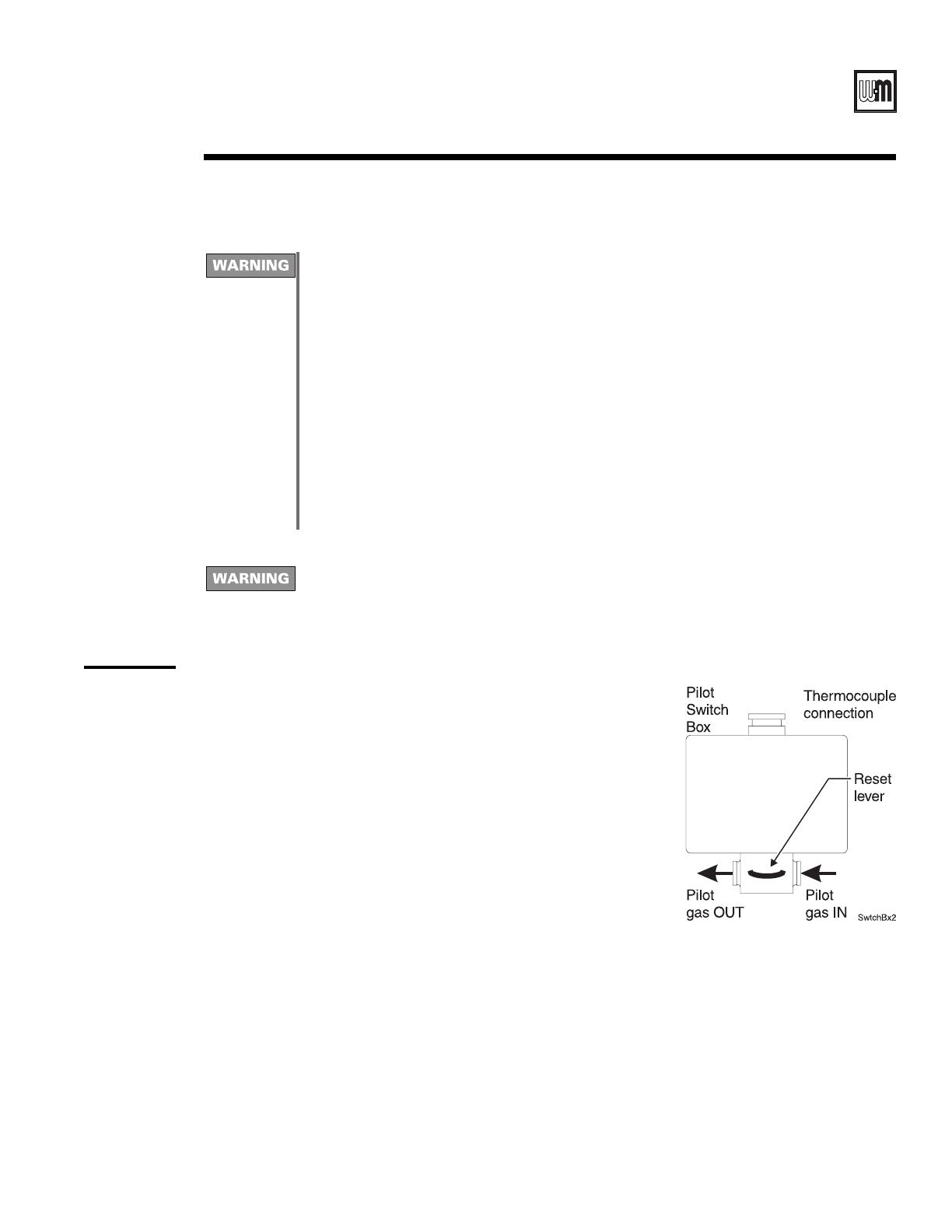
8. Press and hold the reset lever on the Pilot switch box. Manually light the
pilot while holding the lever down. Air in the gas supply line will have to
purge through the line before sufficient gas will reach the pilot.
9. After purging all air, hold the Pilot switch box lever for about 1 minute to
heat the thermocouple.
10. Release the Pilot switch box lever. The pilot should remain lit.
11. Open the Manual main shut-off valve and follow the sequence below.
12. This appliance is also equipped with an ignition device which automatically
lights the second pilot. Do not try to light this pilot by hand.
13. Turn on all electric power to the appliance.
14. Set Operating control to desired setting.
15. If the appliance will not operate, turn off gas to the appliance by closing
the Manual main shut-off valve and Pilot shut-off valve. Call your service
technician or gas supplier.
16. Replace Base access shield and Front panel.
V Operating instructions
Part Number 550-141-797/079810
LGB-6 to LGB-23 Series 2 – Control Supplement
VI Parts list - U.S. boilers
Figure 5
U.S. parts
drawing
Ref. No. Description Size Vendor/Part Number Weil-McLain Part Number
1 Main flame sensor Honeywell 392956 511-724-274
Main burner with pilot bracket Weil-McLain 512-200-055
Main flame sensor bracket Weil-McLain 423-300-420
1" Kinco-Balon 500 511-246-325
1 ¼" Kinco-Balon 600 511-246-330
1" Honeywell V8943A1003 511-044-191
1 ¼" Honeywell V8943A1111 511-044-192
1" Honeywell V8944L1033 511-044-346
1 ¼" Honeywell V8944L1041 511-044-218
6 Pilot burner, standin
g
-repair kit propane Weil-McLain 383-300-410
7 Pilot burner, electronic-repair kit propane Weil-McLain 383-300-411
Main burner with pilot bracket Weil-McLain 512-200-055
Pilot burner bracket Weil-McLain 460-005-624
Honeywell S8620C1003
United Technologies 1003-511
Honeywell V8046C1014
Johnson Controls H91ABG
11 Pilot shut-off valve Kinco-Balon P2R 511-246-340
12 Pilot switch box Johnson Controls L62GB-3C 511-330-229
13 Thermocouple 48" Honeywell Q309A 511-724-245
14 Hi
g
h
g
as pressure switch Honeywell C645B1013 511-624-555
15 Pilot tubing, alum. ¼ O.D. x .032-20" long
16 Pilot tubin
g
, alum. ¼ O.D. x .032-60" lon
g
17 Pressure switch tubin
g
, alum. ¼ O.D. x .032-100" lon
g
*Contact local Weil-McLain distributor/a
g
ent for current replacement part and order number.
4 Secondary gas valve
3 Manual main shut-off valve
Available at Local Supply House
Pilot solenoid10 511-044-039
UCS control module
(2 per control panel)
511-330-097
2
8
Main gas valve5
9
Part Number 550-141-797/0798 11
Universal Control System – Propane gas
VII Parts list - Canadian boilers
Figure 6
Canadian
parts
drawing
Ref. No. Description Size Vendor/Part Number*
1 Main flame sensor Hone
y
well 392956
Main burner with
p
ilot bracket
Main flame sensor bracket
1" Kinco-Balon 500
1 ¼" Kinco-Balon 600
1" Hone
well V8943A1003
1 ¼" Hone
well V8943A1111
1" Hone
y
well V8944N1053
1 ¼" Hone
y
well V8944N1061
Pilot burner, standin
g
Hone
y
well Q327A1642
Pilot orifice, LP, standin
g
Hone
y
well K14
Pilot burner, electronic
Johnson Controls Q90GE-1 or Beckett Gas E48A1
Pilot orifice, LP, electronic
Johnson Controls Y90AA4712 or Beckett Gas 31400
Main burner with
p
ilot bracket
Pilot burner bracket
Hone
y
well S8620C1003
United Technolo
g
ies 1003-511
Hone
y
well V8046C1014
Johnson Controls H91ABG
11 Pilot shut-off valve Conbraco 53-103-01
12 Pilot switch box Johnson Controls L62GB-3C
13 Thermocou
p
le Hone
y
well Q309A2010
14 Hi
g
h
g
as
p
ressure switch Hone
y
well C645B1013
15 Pilot tubin
g
, alum. ¼ O.D. x .032-20" lon
g
16
Pilot tubing, alum. ¼ O.D. x .032-60" long
17 Pressure switch tubin
g
, alum. ¼ O.D. x .032-100" lon
g
1" Watts FBV3-06
1 ¼" Watts FBV3-07
1 ½" Watts FBV3-08
*Contact local Weil-McLain distributor/a
g
ent for current re
p
lacement
p
art and order number.
2 Weil-McLain
6
7
Available at Local Supply House
3 Manual main shut-off valve
4 Secondary gas valve
5 Main gas valve
8 Weil-McLain
18 Firing valve
9
UCS control module
(
2
p
er control
p
anel
)
10 Pilot solenoid
Part Number 550-141-797/079812
LGB-6 to LGB-23 Series 2 – Control Supplement
Weil-McLain
500 Blaine Street
Michigan City, IN 46360-2388
http://www.weil-mclain.com
  • Page 1 1
  • Page 2 2
  • Page 3 3
  • Page 4 4
  • Page 5 5
  • Page 6 6
  • Page 7 7
  • Page 8 8
  • Page 9 9
  • Page 10 10
  • Page 11 11

Weil-McLain LGB-8 User manual

Type
User manual

Ask a question and I''ll find the answer in the document

Finding information in a document is now easier with AI