Standard Horizon CP190i Owner's manual
- Category
- Navigators
- Type
- Owner's manual

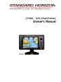
Owner's Manual
CP190i - GPS Chart Plotters

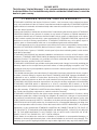
WARNING!!!
Electronic charts displayed by the GPS Chart Plotter are believed to be accurate and
reliable, but are not intended to be a substitute for the official charts, which should
remain your main reference for all matters related to the execution of safe
navigation.
For this reason you should always keep the official published and approved nautical
charts on board.
FCC Compliance Statement
This device complies with Part 15 of the FCC limits for Class A digital devices. This
equipment generates, uses and can radiate radio frequency energy and, if not
installed or used in accordance with the instructions may cause harmful interference
with radio communications.
There is no guarantee that interference will not occur in a particular instance. If this
equipment does cause harmful interference to other equipment, try to correct the
problem by relocating the equipment.
Consult an authorized STANDARD HORIZON dealer or other qualified service
technician if the problem cannot be corrected. Operation is subject to the following
conditions: (1) This device cannot cause harmful interference, and (2) this device
must accept any interference received, including interference that may cause
undesired operation.
Copyright 2013. YAESU MUSEN CO., LTD. All rights reserved. Printed in Italy.
No portion of this manual may be reproduced without the permission of YAESU MUSEN CO., LTD.
OM CODE: S4x2SH5c_0ww 16.70gD78 - 031213e

CLEANING PROCEDURE FOR THE GPS CHART PLOTTER SCREEN
Cleaning of the chart plotter screen is a very important operation and must be done
carefully. Since the surface is covered by a antireflective coating, the procedure for
cleaning all the surfaces can be performed using the following procedure: Use a
clean, soft, lint-free cloth to clean the glass. We recommend using a micro-fiber
cloth. Spray a small amount of ammonia-free cleaner (isopropyl alcohol) onto the
cloth. Spraying on the cloth will prevent overspray. Fold the cloth or lens cloth into
a triangular shape, moisten the tip and use the index finger behind a corner to move
the cloth across the surface in overlapping side to side strokes. If the cloth is too wet,
a noticeable wet film will be left in its path and you will need to repeat the process.
If too dry, the cloth won’t glide easily, and may damage the surface.
CAUTION
· The GPS Chart Plotter is designed for maritime use. To avoid water intrusion, ensure
the C-MAP B
Y JEPPESEN C-CARD door is completely closed.
· Extensive exposure to heat may result in damage to the GPS Chart Plotter.
· The GPS Chart Plotter contains dangerous high-voltage circuits which only experien-
ced technicians can handle.
· STANDARD HORIZON will not be liable for errors contained herein, or for incidental
or consequential damages in connection with the performance or use of this material.
· Because we frequently update our software and applications, the pictures shown
through this Owner’s Manual may be slightly different from what you see.

Page 6 CP190i
TABLE OF CONTENTS
1. INTRODUCTION ......................................................................................................11
1.0 GENERAL INFORMATION ....................................................................................11
1.1 PACKING LIST ......................................................................................................11
1.1.0 Packing List................................................................................................12
1.2 OPTIONAL ACCESSORIES ..................................................................................12
1.3 OPTIONAL DOME OR OPEN ARRAY RADAR ANTENNAS................................12
2. INSTALLATION ......................................................................................................14
2.0 MOUNTING THE GPS CHART PLOTTER ............................................................14
2.1 BRACKET MOUNTING ..........................................................................................14
2.2 FLUSH MOUNTING................................................................................................15
2.3 MOUNTING THE OPTIONAL EXTERNAL GPS ANTENNA .................................16
2.3.0 Flush Mounting the Antenna...................................................................... 16
2.4 CONNECTIONS ..................................................................................................... 17
2.4.0 CP190i Connection Table..........................................................................18
2.4.1 CP190i Connections ..................................................................................18
2.5 BATTERY CONNECTIONS ...................................................................................20
2.6 NMEA CONNECTIONS..........................................................................................20
2.7 GPS POSITION ON A VHF RADIO ....................................................................... 20
2.8 OPTIONAL BLACK BOX FISH FINDER ................................................................21
2.9 RADAR ANTENNA (USA ONLY) ...........................................................................21
2.10 PERSONAL COMPUTER CONNECTIONS...........................................................21
2.11 NMEA DATA PAGE................................................................................................22
2.12 DEMO MODE (For DEALER USE) ........................................................................ 22
3. CONTROLS AND INDICATORS ...................................................................................... 24
3.0 CONTROLS AND CONNECTIONS ....................................................................... 24
3.1 GETTING STARTED ..............................................................................................25
3.1.0 Power On, Off and ShuttlePoint Knob Operation...................................... 25
3.1.1 Cursor Vs. Home Mode ............................................................................. 27
3.1.2 Cursor and Menu Selection Speed............................................................27
3.1.3 Changing the Ship Icons ...........................................................................27
3.1.4 Changing Backlight and Contrast ..............................................................28
3.1.5 Selecting North Up or Course Up .............................................................. 28
3.2 TIME SETUP ......................................................................................................29
3.3 SELECTING LORAN TD OR OTHER COORDINATE SYSTEM .......................... 30
3.4 CHANGING THE Display COLOR ......................................................................... 31
3.5 SELECTING LANGUAGE ......................................................................................31
3.6 SETTINGS IN GENERAL SETUP MENU..............................................................32
3.7 ABOUT PAGE ......................................................................................................34
4. FIND SERVICES ......................................................................................................36
4.0 USING FIND SERVICES & MORE FUNCTIONS..................................................36
4.0.0 Port Services..............................................................................................36
4.0.1 Port ......................................................................................................37
4.0.2 Tide Stations .............................................................................................. 37
4.0.3 Wrecks ......................................................................................................38
4.0.4 Obstructions...............................................................................................39
4.0.5 Lakes Information ...................................................................................... 40
4.0.6 Lakes By Name .........................................................................................41

CP190i Page 7
4.0.7 Points Of Interest .......................................................................................42
4.0.8 User Points ................................................................................................ 43
4.0.9 Coordinates................................................................................................43
4.0.10 Information .................................................................................................44
5. MAX CARTOGRAPHY OVERVIEW.................................................................................45
5.0 INSERTING THE OPTIONAL MAX C-CARD ........................................................ 45
6. MAP FUNCTIONS ......................................................................................................47
6.0 MAX FUNCTIONS MENU ...................................................................................... 47
6.0.0 Zoom Type .................................................................................................47
6.0.1 Icons Size .................................................................................................. 48
6.0.2 Place Names Size ..................................................................................... 48
6.0.3 Perspective View .......................................................................................49
6.0.4 Dynamic Nav-Aids .....................................................................................50
6.0.5 Safety Status Bar (DSI - Data Safety Indicator)........................................50
6.0.6 Satellite Imagery ........................................................................................51
6.0.7 Currents Prediction ....................................................................................51
6.0.8 Chart Language ......................................................................................... 52
6.0.9 Pictures or Diagrams ................................................................................. 53
How to Show Pictures or Diagrams of an Object......................................53
6.0.10 Enhanced Port Info ....................................................................................54
7. CREATING MARKS ......................................................................................................55
7.0 CREATING A NEW MARK USING THE CHART PAGE ....................................... 55
7.1 EDITING A MARK .................................................................................................. 55
7.1.0 Deleting a Mark or Waypoint .....................................................................56
7.1.1 Moving a Mark or Waypoint .......................................................................56
7.2 MARKS/WAYPOINTS LIST ................................................................................... 57
7.3 CREATING A NEW MARK WITH THE USER POINTS LIST ...............................58
7.4 GOTO CURSOR, ROUTE AND MARK..................................................................59
7.4.0 Goto Cursor ...............................................................................................59
7.4.1 Goto Route.................................................................................................60
7.4.2 Goto Mark ..................................................................................................60
7.4.3 Stop Navigation to Destination ..................................................................60
8. MAN OVER BOARD (MOB) FUNCTION .........................................................................61
8.0 PLACING A MOB POINT ....................................................................................... 61
8.1 DELETING A MOB POINT .....................................................................................61
9. ROUTES ......................................................................................................62
9.0 CREATING A ROUTE USING WAYPOINTS ........................................................ 62
9.1 CHANGING THE NAME OF A ROUTE ................................................................. 63
9.2 CREATING AN OLYMPIC ROUTE ........................................................................63
9.3 MAKING ADDITIONAL ROUTES...........................................................................64
9.4 CREATING A ROUTE USING MARKS ON THE CHART PAGE..........................64
9.5 INSERTING A WAYPOINT INTO A ROUTE .........................................................65
9.6 GOTO A ROUTE .................................................................................................... 65
9.6.0 Using [GOTO] to Select Route ..................................................................65
9.6.1 Using the ShuttlePoint knob ...................................................................... 66
9.7 DELETING A ROUTE.............................................................................................66
9.8 OTHER SETTINGS IN ROUTE MENU ..................................................................67
9.8.0 Route Check ..............................................................................................67
10. TRACKS ......................................................................................................69
10.0 TRACKING ......................................................................................................69
10.0.0 Saving and Starting a New Track ..............................................................70

Page 8 CP190i
10.0.1 Deleting a Track.........................................................................................70
10.0.2 Other Settings ............................................................................................ 70
10.1 TRIP LOG ......................................................................................................71
10.1.0 Using the Trip Log ..................................................................................... 71
10.1.1 Setup / Reset .............................................................................................71
11. USER C-CARD ......................................................................................................72
11.0 USER C-CARD MENU ...........................................................................................72
11.0.0 Formatting the Optional User C-CARD .....................................................72
11.0.1 Transferring Files to the Optional User C-CARD ......................................72
11.0.2 Loading a File from the Optional User C-CARD .......................................73
11.0.3 Deleting a File from the Optional User C-CARD ....................................... 73
11.0.4 Refreshing the Optional User C-CARD ..................................................... 73
12. PAGES ......................................................................................................74
12.0 CHART PAGE ...................................................................................................... 74
12.0.0 Change Focus on Dual Chart Page .......................................................... 75
12.0.1 Single Chart Page......................................................................................75
12.0.2 Window Selections ....................................................................................76
12.0.3 Customizing Data Windows.......................................................................76
12.0.4 Additional Functions on Chart Page: Information on Objects...................78
12.0.5 Display Mode .............................................................................................78
12.0.6 Marine Settings .......................................................................................... 79
12.0.7 Depth Settings ...........................................................................................80
12.0.8 Land Settings .............................................................................................80
12.0.9 Chart Settings ............................................................................................81
12.0.10Underwater Objects Settings ..................................................................... 82
12.1 CUSTOMIZING CHART SETTINGS ...................................................................... 83
12.2 NAVIGATION PAGE .............................................................................................. 83
12.3 HIGHWAY PAGE ...................................................................................................84
12.4 CELESTIAL PAGE .................................................................................................84
12.5 GPS STATUS PAGE..............................................................................................85
12.5.0 GPS Setup Menu .......................................................................................86
12.5.1 WAAS/EGNOS Setting.............................................................................. 86
12.6 NMEA DISPLAY PAGE ..........................................................................................86
12.7 NMEA DATA PAGE................................................................................................87
12.8 NMEA TREND PAGES ..........................................................................................88
12.9 VHF DIGITAL SELECTIVE CALLING .................................................................... 88
12.9.0 Interfacing ..................................................................................................89
12.9.1 Distress Call...............................................................................................89
12.9.2 Position Request........................................................................................89
12.9.3 DSC Directory ............................................................................................90
13. ADVANCED SETTINGS ................................................................................................... 91
13.0 INPUT/OUTPUT (NMEA, AIS, RADAR) ................................................................ 91
13.0.0 Input ......................................................................................................91
13.0.1 Ouput ......................................................................................................91
13.1 NAVIGATE ......................................................................................................92
13.1.0 Loran TD .................................................................................................... 92
13.2 COMPASS ......................................................................................................93
13.3 ALARMS ......................................................................................................93
13.4 SIMULATION ......................................................................................................94
13.4.0 Navigating a Route in Simulation Mode ....................................................95
13.5 DSC POLLING ......................................................................................................95

CP190i Page 9
14. AIS ......................................................................................................96
14.0 SYSTEM DEFINITIONS ......................................................................................... 96
14.1 AIS SETUP MENU .................................................................................................97
14.2 QUICK INFO ON AIS TARGET..............................................................................97
14.3 AIS TARGET COLORS ..........................................................................................98
14.4 AIS-SART ......................................................................................................98
14.4.0 AIS-SART Test Mode ................................................................................ 98
14.5 AIS LIST ......................................................................................................99
14.6 Enhanced AIS Page ...............................................................................................99
14.6.0 AIS Vessel Types .................................................................................... 100
15. C-WEATHER SERVICE.................................................................................................. 102
15.0 C-WEATHER SERVICE MENU ...........................................................................102
15.0.0 Download .................................................................................................102
15.0.1 Copy from User C-CARD.........................................................................103
15.0.2 Weather Forecast ....................................................................................103
15.0.3 Real Time View........................................................................................103
15.0.4 Type of Data ............................................................................................ 103
16. MOBILARM ....................................................................................................104
16.0 MOBILARM-GPS CHART PLOTTER CONNECTION .........................................104
16.1 SOFTWARE SETUP ............................................................................................105
16.2 MOBILARM STATUS ........................................................................................... 105
16.3 MOBILARM PTX...................................................................................................106
16.3.0 MOBILARM MOB alert is received .......................................................... 106
16.4 PLACING CURSOR ON THE PTX ICON ............................................................ 107
16.4.0 Delete PTX...............................................................................................107
16.4.1 Goto PTX ................................................................................................. 108
16.4.2 The MOBILARM Alarm Status List.......................................................... 108
17. TROUBLESHOOTING....................................................................................................110
18. TECHNICAL TESTS ....................................................................................................111
18.0 SYSTEM TEST ....................................................................................................111
18.0.0 RAM Menu (reset)....................................................................................111
18.0.1 DIM Menu.................................................................................................111
18.0.2 Cartridges.................................................................................................112
18.0.3 Serial Ports ..............................................................................................112
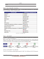
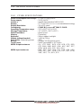
19. SPECIFICATIONS ....................................................................................................113
19.0 CP190i SPECIFICATIONS...................................................................................113
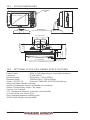
19.1 CP190i DIMENSIONS ..........................................................................................114
19.2 OPTIONAL FF525 FISH FINDER SPECIFICATIONS.........................................114
19.3 OPTIONAL WAAS GPS RECEIVER SPECIFICATIONS.................................... 115
20. APPENDIX: TERMS ....................................................................................................116
ANALYTICAL INDEX ....................................................................................................118

Page 10 CP190i

CP190i Page 11
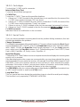
1. INTRODUCTION
Congratulations on your purchase of the STANDARD HORIZON GPS Chart Plotter.
Whether this is your first STANDARD HORIZON product or not, we are committed to
ensuring your enjoyment and satisfaction with this unit. Our Technical support personnel
stand behind every product we sell. Customers should contact STANDARD HORIZON on
714-827-7600 or email to
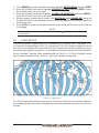
1.0 GENERAL INFORMATION
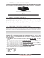
The CP190i (with internal GPS antenna) is a precision-crafted high-performance receiver for
the Global Positioning System (WAAS GPS) constellation of satellites that provide precise
location data with a host of navigation features and is ideal for nautical use and sealed against
water ingress. The CP190i is housed in rugged, impact-resistant cases with outstanding
ergonomic design for effortless operation. The CP190i is IP56 water resistent.
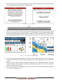
The advanced features of the GPS Chart Plotter include:
· 2Nm C-MAP World Wide Background chart included
· 5” 320x232 high resolution sunlight-readable display
· Internal 50 channel WAAS GPS antenna
· Optional external 50 channel WAAS GPS antenna with 15m (50ft) of cable
· Fish Finder capable when connected to optional FF525 50/200kHz (Black Box Fish
Finder)
· AIS capable (Color AIS Targets, AIS List Enhanced page, AIS-SART, AIS-MOB and
AIS-EPIRB handling) when connected to an optional AIS device
· C-MAP Weather Service predictions
· Dual Chart page with independent zoom levels
· Selectable Sail boat and Power boat Ship Icons with Compass Rose indication
· Route Check
· Grounding Alarm
· SOG Speed Filter function to resolve erratic speed readings in rough seas
· Displays DSC Distress and Position Report calls received from a DSC VHF radio
· Dedicated MARK, ROUTE and FIND keys
· Supplied swivel mounting bracket and flush mounting hardware
· NMEA-0183 connections: 2 Inputs, 3 Outputs
· 3000 Marks / 50 Routes / 10000 Track Points
· 3 years waterproof warranty
1.1 PACKING LIST
When the package containing the Navigation device is first opened, please check for the
following contents. If any parts are missing contact the dealer this Navigation device was
purchased from.Accessories and replacements parts may be ordered in the USA by
contacting STANDARD HORIZON’s Parts department on 714-827-7600 Extn. 6800 or by
email at

Page 12 CP190i
1.1.0 Packing List
PART CODE ITEM
S8002224A External bracket
S8002225 Mounting knob with two washers
S8002222 Dust cover
T9101553 Power Data Cable
S8002223 Flush mounting screws
EM022U500 Flush mount template
XUCMP0052 2 Amp fuse and holder
EM050U102 Owner’s Manual
EM023U513 Quick Reference Guide
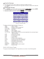
1.2 OPTIONAL ACCESSORIES
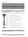
1.3 OPTIONAL DOME OR OPEN ARRAY RADAR ANTENNAS
The Radar antennas are supplied by SI-TEX (631) 996-2690 in the USA and Canada. Refer
to the following table for compatible models:

CP190i Page 13
MODEL NUMBER DESCRIPTION
MDS-1 2kW 24 Mile 12.4” diameter Radome antenna
MDS-8 2kW 24 Mile 20” diameter Radome antenna
MDS-9 4kW 36 Mile 23.5” diameter Radome antenna
MDS-10-4 4kW 48 Mile 4ft Open Array
MDS-10-5 4kW 48 Mile 5ft Open Array
NOTE
For additional information, refer to the Radar Installation and Radar Operation Manuals located at
www.standardhorizon.com.

Page 14 CP190i
2. INSTALLATION
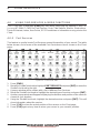
NOTE
Throughout this Owner’s Manual same conventions are used. See the legend below:
[MENU]If you see brackets around a bold and capital letter word this refers to a key press.
GENERAL SETUP When a word(s) is bold capital letters and underlined, this refers to a menu
selection item.
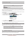
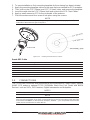
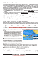
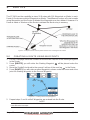
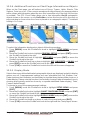
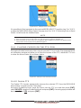
A GPS receiver with antenna is located inside the CP190i, which is designed to be bracket
mounted. It may be flush mounted, however an optional external GPS antenna may be
needed to receive GPS satellite signals.
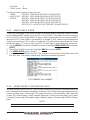
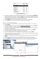
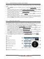
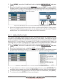
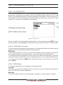
To use the external GPS antenna, the internal GPS antenna must be turned off, using the
procedure below:
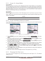
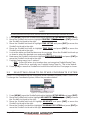
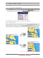
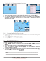
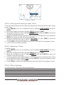
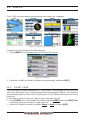
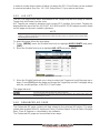
1. Turn the CP190i On and select the
GPS STATUS page.
2. Press [ENT] to show the
GPS SETUP menu.
3. Move the ShuttlePoint knob to highlight
INTERNAL GPS and press [ENT].
4. Move the ShuttlePoint knob to highlight
OFF and press [ENT].
Figure 2 - GPS Setup menu
5. Press [CLR] to exit the GPS SETUP menu.
6. Confirm the GPS Status page is showing satellite signal strength bars and receive a fix.
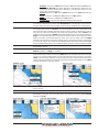
2.0 MOUNTING THE GPS CHART PLOTTER
The CP190i is supplied with a swivel mounting bracket which allows them to be dash
mounted. When flush mounting, the optional GPS antenna may be needed to receive GPS
satellite signals. Refer to the images below for Bracket and Flush mounting.
NOTE
The CP190i is designed to be bracket and flush mounted. However when bracket mounting the
CP190i in an area where satellite reception is not possible with the internal antenna or when flush
mounted, the optional GPS antenna must be installed.
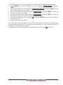
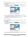
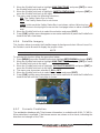
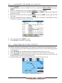
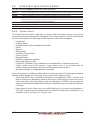
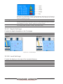
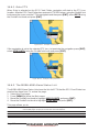
2.1 BRACKET MOUNTING
Before installing ensure the area the bracket is mounted to is strong enough to support the
weight of the GPS Chart Plotter especially while under way. After the location is found,
attach the mounting base to the area using the supplied hardware.

CP190i Page 15
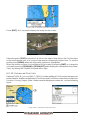
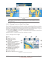
Figure 2.1 - Example of Bracket installation on CP190i
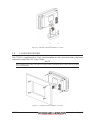
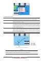
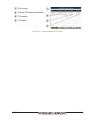
2.2 FLUSH MOUNTING
The CP190i is supplied with a Flush mount template for the cutout hole and screw holes
required to install the GPS Chart Plotter.
NOTE
Before drilling holes make sure there is enough room to mount the GPS Chart Plotter and there
are no obstructions.
Figure 2.2 - Example of Flush installation on CP190i

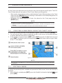
Page 16 CP190i
1. After a location is found, peel the template label from the backing and apply the label
to the mounting area.
2. Drill a hole in one area of the cutout area that will allow the blade of a jig saw to be
inserted. Insert and cut out the area on the panel using the jig saw.
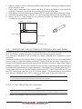
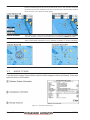
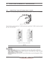
3. Next drill the four holes required to insert the GPS Chart Plotter with the mounting studs.
4. Install the mounting studs on the GPS Chart Plotter and insert into the mounting hole.
5. Attach the GPS Chart Plotter to the mounting location by attaching the supplied
hardware to the mounting studs.
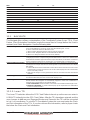
M4 threaded
M4 threaded
20 mm4mm
27 mm
Figure 2.2.0 - Mounting Screws
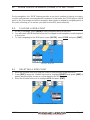
2.3 MOUNTING THE OPTIONAL EXTERNAL GPS ANTENNA
An external WAAS GPS antenna is available when the CP190i is flush mounted or mounted
in an area where satellite reception is not possible with the internal antenna.
This antenna is designed to be mounted on a base, installed on an extension or flush
mounted.
Choose a location for the antenna that has a clear view of the sky and is not located within
3ft of a Radar or other transmitting antennas. Ensure there are no major obstructions or
fixtures in the immediate proximity to the antenna. The antenna relies on direct “line of sight”
satellite reception. If you are unsure of the chosen location, temporarily mount the antenna
in the desired location to verify correct operation. If mounted close to Radar, after the GPS
Chart Plotter has a fix, turn on the Radar to ensure the GPS Chart Plotter holds the fix (use
the GPS Status page, see Par. 12.5 “GPS Status page”). The thread used on the antenna
is an industry standard (1inch 14TPI) used on a wide range of mounting brackets.
NOTE
The antenna cable can be cut and spliced to ease installation. Care must be taken when
reconnecting the antenna cable to protect from water and corrosion.
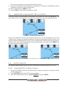
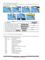
2.3.0 Flush Mounting the Antenna
NOTE
Before drilling holes, it is recommended the antenna be positioned where the location is planned,
cable connected to the GPS Chart Plotter and power turned on to ensure a GPS Fix is received.
1. Remove the threaded base from the antenna dome.

CP190i Page 17
2. To ease installation a flush mounting template for the antenna has been included.
3. Apply the mounting template sticker to the area that was verified for GPS reception.
4. Then, drill out the 0.78” (20mm) and 0.13” (3.2mm) holes, and remove the template.
5. Insert the cable into the 0.78” (20mm) hole and route to the GPS Chart Plotter.
6. Apply a small amount or RTV to the underside of the antenna.
7. Place the antenna and then screw it into place using the screws.
NOTE
In some cases the screw may not be long enough. If this happens simply apply more RTV to the
underside of the antenna to glue it into place.
S8002348
Figure 2.3.0 - Installing the External GPS antenna
Smart GPS Cable
Pin Wire Color Description
1 Red Battery Positive
2 Green Smart GPS NMEA Input
3 Brown Smart GPS NMEA Output
4NC
5NC
6 Black/Yellow Battery Ground
2.4 CONNECTIONS
The CP190i has connectors that allow them to be connected to a Power supply, optional
WAAS GPS antenna, optional FF525 50/200kHz Black Box Fish Finder and NMEA
Devices* such as VHFs, AIS Receiver, Digital Instruments and Autopilots.
NOTE*
RS232 not opto-isolated electrical interface.
NOTE
The GPS Chart Plotter can send many sentences to external NMEA devices*. The NMEA Output
wires are yellow and white. If you have connected devices as shown in the table on the next page
and need to feed NMEA to other devices (Autopilot, RADAR…) you can parallel wires from the
yellow, brown or white wires to other devices.

Page 18 CP190i
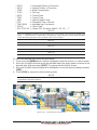
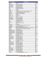
2.4.0 CP190i Connection Table
Power Data Cable
Pin Wire Color Description Connection Example Additional Comments
1 Black Battery Ground Connect to Battery Ground
2 Red Battery Positive Connect to Battery Positive
3 Green NMEA Common Common (ground) for NMEA devices**
4 Blue Port1 Input Connect to Output of NMEA devices** Default is NMEA 0183
5 Brown Port1 Output Connect to Input of NMEA devices** Default is NMEA 0183 with GGA, GLL, RMC,
DBT, DPT, MTW, VHW and XTE sentences
6 Grey Port2 Input Connect to FF525 Default is Fish Finder
7 White Port2 Output Connect to FF525 Default is Fish Finder
8 Yellow Port3 Output Connect to Input of NMEA devices** Default is NMEA 0183 with APA, APB, BOD,
GGA, GLL, RMC and BOD sentences*
NOTE* AUTOPILOT CONNECTION
Care must be taken when connecting the GPS Chart Plotter to an Autopilot. Normally Port3 (Yellow
wire) will be used to connect to an Autopilot input, however older autopilots may not be able to read
the sentences due to the talker ID that is being used (II Integrated Instrument). If the Autopilot
connections are made to Port3 (Yellow wire) and the Autopilot is not reading the sentences, change
the connections to Port1 (Brown wire) and change the sentences to APA, APB, BOD, GGA, GLL,
RMC and XTE.
NOTE**
RS232 not opto-isolated electrical interface.
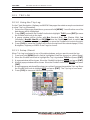
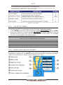
2.4.1 CP190i Connections
2.4.1.0 DC Power Connection
Battery
10-35Vdc
Red
2A
Fuse
Black
Switch
+
-
PWR & ACC 1 Cable
Optional WAAS
GPS Antenna
CP190i

CP190i Page 19
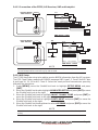
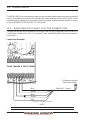
2.4.1.1 Connection of the FF525, AIS Receiver, VHF and Autopilot
Optional WAAS
GPS Antenna
CP190i
Battery
10-35Vdc
Red
2A
Fuse
Black
Switch
+
-
VHF
PILOT
Green
Blue
Brown
Gray
White
NMEA Common
Port 1 Input
Port 1 Output
Port 2 Input
Port 2 Output
Yellow Port 3 Output
AIS
PWR & ACC 1 Cable
Battery
10-35Vdc
Red
2A
Fuse
Black
Switch
+
-
Tee
Optional
Fish Finder
Transducer
VHF
Green
Blue
Brown
Gray
White
NMEA Common
Port 1 Input
Port 1 Output
Port 2 Input
Port 2 Output
Yellow Port 3 Output
AIS
PWR & ACC 1 Cable
Optional WAAS
GPS Antenna
CP190i
NOTE
Port2 Input and Output is used by the optional FF525. In the diagram above you will notice Port2
Input and Output wires are shown in gray and not used.
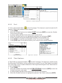
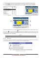
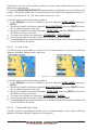
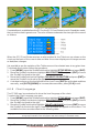
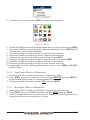
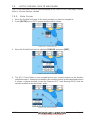
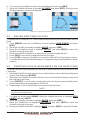
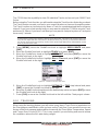
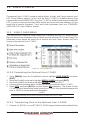
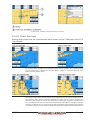
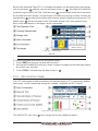
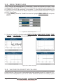
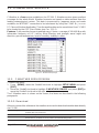
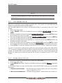
2.4.1.2 AIS Setup
The CP190i has to be set up to be able to receive NMEA information from the AIS receiver.
The GPS Chart Plotter reads the AIS NMEA message VMD, type 1, 2, 3 and 5 for AIS Class
A and type 18, 19, 24 for AIS Class B. Select the used port and transmission speed by
following the procedure:
1. Press [MENU], move the ShuttlePoint knob to highlight SETUP MENU and press
[ENT].
2. Move the ShuttlePoint knob to highlight
ADVANCED SETUP and press [ENT] or move
the ShuttlePoint knob to the right.
3. Move the ShuttlePoint knob to highlight
IN/OUT CONNECTIONS and press [ENT] or
move the ShuttlePoint knob to the right.
4. Move the ShuttlePoint knob to highlight
PORT1 INPUT and press [ENT] or move the
ShuttlePoint knob to the right.
5. Move the ShuttlePoint knob up/down to select
AIS 38400 and press [ENT] or move the
ShuttlePoint knob to the right.
NOTE
If an AIS receiver is not connected, Port1 Input can be connected to most DSC VHF’s for position
polling.

Page 20 CP190i
2.5 BATTERY CONNECTIONS
1. The GPS Chart Plotters are supplied with a fuse and holder. This fuse should be
installed into the Black wire to protect the NMEA Output/Input circuits from possible
damaged.
2. Connect the Red and Black wires from the GPS Chart Plotter to a 12VDC source as
directly as possible.
2.6 NMEA CONNECTIONS
The GPS Chart Plotter can be connected to external devices with NMEA and display
information. Examples:
· DSC VHF Radio
· Depth Sounder, Speed Log, Wind Instrument, Autopilot etc.
· Radar (USA O
NLY)
· Personal Computer
· AIS Receiver
· MOBILARM System
2.7 GPS POSITION ON A VHF RADIO
STANDARD HORIZON has pioneered Digital Selective Calling (DSC) on VHF radios.
Advancements in DSC have made it possible to show the coordinates of a vessel that has
transmitted a DSC Distress Call or even Polled the location of another vessel and show the
position of that vessel on the display of STANDARD HORIZON VHFs.
STANDARD HORIZON has taken this feature one step further. If a CP190i is connected to
a DSC capable VHF, the vessel in Distress or the polled position of the vessel is shown on
the display of the GPS Chart Plotter, making it easy to navigate to the location of the vessel.
This is a great feature that could save someone’s life or for anyone wanting to know the
position of another vessel.
Other DSC VHF Manufactures
GPS Chart Plotter Description VHF
Green NMEA Common Ground Connect to NMEA Ground
Brown NMEA Positive Output Connect to NMEA Input
Blue NMEA Positive Input * Connect to NMEA Output (if available)
* Some manufacturers of DSC VHF’s are not capable of outputting NMEA DSC and DSE sentences to
the CP190i. Refer to the Owner’s Manual and confirm the VHF can output NMEA DSC and DSE
sentences.
NOTE
Refer to VHF Digital Selective Calling Section for operation.

CP190i Page 21
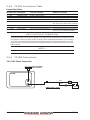
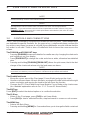
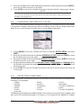
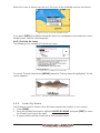
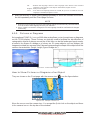
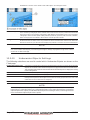
2.8 OPTIONAL BLACK BOX FISH FINDER
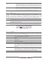
STANDARD HORIZON offers an optional Black Box Fish Finder called the FF525. Please
refer to the Owner's Manual supplied with the Fish Finder for connections and operations.
Figure 2.8 - FF525 50/200kHz Black Box Fish Finder
NOTE
The FF520 is also compatible.
2.9 RADAR ANTENNA (USA ONLY)
Please refer to Par. 1.3 ”Optional Dome or Open Array Radar Antennas”. The Radar
antenna includes the necessary electronics to deliver Radar information to a compatible
STANDARD HORIZON GPS Chart Plotter, and is supplied with mounting hardware kit,
interconnection cable and a Radar Junction Box. Please refer to the Radar Installation
Manual and Radar Operation Manual available at www.standardhorizon.com.
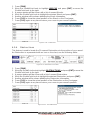
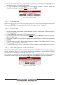
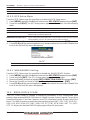
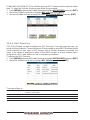
2.10 PERSONAL COMPUTER CONNECTIONS
The GPS Chart Plotter can be connected to output Marks and Routes to many available PC
programs. To send or receive User Points the PC Program must be able to receive NMEA
WPL and RTE sentences. Refer to the table below for connection to a Serial DB9 connector.
Pin PC DB9 connection Port 1 connection
2 Receive Brown
3 Transmit Blue
5 Signal ground Green
By default Port1 is set to receive or send User Points to and from a PC. The GPS Chart
Plotter may be set up to send and receive the User Points on a different Port using the
following procedure:
1. Press [MENU], move the ShuttlePoint knob to highlight
SETUP MENU and press
[ENT].
2. Move the ShuttlePoint knob to highlight
ADVANCED SETUP and press [ENT] or move
the ShuttlePoint knob to the right.
3. Move the ShuttlePoint knob to highlight
IN/OUT CONNECTIONS and press [ENT] or
move the ShuttlePoint knob to the right.
4. Move the ShuttlePoint knob to highlight
SEND/REC RTE & MARKS and press [ENT]
or move the ShuttlePoint knob to the right to show the popup window.
5. Move the ShuttlePoint knob to desired Port and press [ENT].
The PC COM settings are:
· Baud Rate : 4800
· Parity : None
· Data Bits : 8

Page 22 CP190i
· Stop Bits : 1
· Flow Control : None
The format of the sentences that are sent:
· MARK $GPWPL,3249.061,N,00710.651,E,MRK002*22
· WAYPOINT $GPWPL,3933.008,N,00639.969,E,WPT012*22
· ROUTE $GPWPL,2544.362,N,08011.672,W,WPT003*32
$GPWPL,2543.921,N,08011.481,W,WPT004*31
$GPWPL,2543.493,N,08011.768,W,WPT005*37
$GPRTE,2,1,c,ROUTE01,WPT003,WPT004,WPT005*21
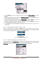
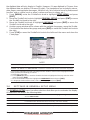
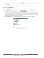
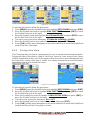
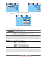
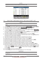
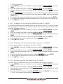
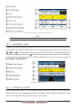
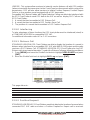
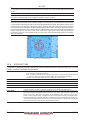
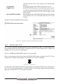
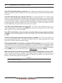
2.11 NMEA DATA PAGE
The NMEA Data page is very useful to see if an external device (example: Depth Sounder)
is transmitting NMEA sentences to the GPS Chart Plotter. This page can also be used to
see if the GPS Chart Plotter NMEA Output is being loaded down by an external NMEA
device the GPS Chart Plotter is connected to. Example: A VHF radio is connected but the
radio is not receiving a GPS Position. Usually the VHF radio will be connected to the Green
and Brown wires. To check to see if the GPS Chart Plotter is transmitting the sentences:
1. Press [MENU], move the ShuttlePoint knob to highlight
NMEA DISPLAY and press
[ENT].
2. Move the ShuttlePoint knob to highlight
DATA and press [ENT].
3. The
NMEA DATA page is shown.
4. Connect the Blue Wire on the GPS Chart Plotter to the junction of the Brown wire and
the VHF wire. The display should look similar to the following picture.
Figure 2.11 - NMEA Data page
2.12 DEMO MODE (FOR DEALER USE)
In Demonstration Mode the GPS Chart Plotter automatically places a Destination point on
the Chart page and simulates navigation to the point. Also, the active page displayed on the
screen changes every 10 seconds. The pages are shown in the following order: Start-Up
screen, GPS Status page, Chart/Compass tape page, Chart/Fish Finder page, Fish Finder
Full page, Radar page, Navigation page, Highway page, Celestial page, NMEA Display
page.
NOTE
This mode is used by dealers to promote the features of the CP190i when on a retail shelf.
Page is loading ...
Page is loading ...
Page is loading ...
Page is loading ...
Page is loading ...
Page is loading ...
Page is loading ...
Page is loading ...
Page is loading ...
Page is loading ...
Page is loading ...
Page is loading ...
Page is loading ...
Page is loading ...
Page is loading ...
Page is loading ...
Page is loading ...
Page is loading ...
Page is loading ...
Page is loading ...
Page is loading ...
Page is loading ...
Page is loading ...
Page is loading ...
Page is loading ...
Page is loading ...
Page is loading ...
Page is loading ...
Page is loading ...
Page is loading ...
Page is loading ...
Page is loading ...
Page is loading ...
Page is loading ...
Page is loading ...
Page is loading ...
Page is loading ...
Page is loading ...
Page is loading ...
Page is loading ...
Page is loading ...
Page is loading ...
Page is loading ...
Page is loading ...
Page is loading ...
Page is loading ...
Page is loading ...
Page is loading ...
Page is loading ...
Page is loading ...
Page is loading ...
Page is loading ...
Page is loading ...
Page is loading ...
Page is loading ...
Page is loading ...
Page is loading ...
Page is loading ...
Page is loading ...
Page is loading ...
Page is loading ...
Page is loading ...
Page is loading ...
Page is loading ...
Page is loading ...
Page is loading ...
Page is loading ...
Page is loading ...
Page is loading ...
Page is loading ...
Page is loading ...
Page is loading ...
Page is loading ...
Page is loading ...
Page is loading ...
Page is loading ...
Page is loading ...
Page is loading ...
Page is loading ...
Page is loading ...
Page is loading ...
Page is loading ...
Page is loading ...
Page is loading ...
Page is loading ...
Page is loading ...
Page is loading ...
Page is loading ...
Page is loading ...
Page is loading ...
Page is loading ...
Page is loading ...
Page is loading ...
Page is loading ...
Page is loading ...
Page is loading ...
Page is loading ...
Page is loading ...
Page is loading ...
Page is loading ...
Page is loading ...
Page is loading ...
Page is loading ...
-
 1
1
-
 2
2
-
 3
3
-
 4
4
-
 5
5
-
 6
6
-
 7
7
-
 8
8
-
 9
9
-
 10
10
-
 11
11
-
 12
12
-
 13
13
-
 14
14
-
 15
15
-
 16
16
-
 17
17
-
 18
18
-
 19
19
-
 20
20
-
 21
21
-
 22
22
-
 23
23
-
 24
24
-
 25
25
-
 26
26
-
 27
27
-
 28
28
-
 29
29
-
 30
30
-
 31
31
-
 32
32
-
 33
33
-
 34
34
-
 35
35
-
 36
36
-
 37
37
-
 38
38
-
 39
39
-
 40
40
-
 41
41
-
 42
42
-
 43
43
-
 44
44
-
 45
45
-
 46
46
-
 47
47
-
 48
48
-
 49
49
-
 50
50
-
 51
51
-
 52
52
-
 53
53
-
 54
54
-
 55
55
-
 56
56
-
 57
57
-
 58
58
-
 59
59
-
 60
60
-
 61
61
-
 62
62
-
 63
63
-
 64
64
-
 65
65
-
 66
66
-
 67
67
-
 68
68
-
 69
69
-
 70
70
-
 71
71
-
 72
72
-
 73
73
-
 74
74
-
 75
75
-
 76
76
-
 77
77
-
 78
78
-
 79
79
-
 80
80
-
 81
81
-
 82
82
-
 83
83
-
 84
84
-
 85
85
-
 86
86
-
 87
87
-
 88
88
-
 89
89
-
 90
90
-
 91
91
-
 92
92
-
 93
93
-
 94
94
-
 95
95
-
 96
96
-
 97
97
-
 98
98
-
 99
99
-
 100
100
-
 101
101
-
 102
102
-
 103
103
-
 104
104
-
 105
105
-
 106
106
-
 107
107
-
 108
108
-
 109
109
-
 110
110
-
 111
111
-
 112
112
-
 113
113
-
 114
114
-
 115
115
-
 116
116
-
 117
117
-
 118
118
-
 119
119
-
 120
120
-
 121
121
-
 122
122
-
 123
123


Standard Horizon CP190i Owner's manual
- Category
- Navigators
- Type
- Owner's manual
Ask a question and I''ll find the answer in the document
Finding information in a document is now easier with AI
Related papers
-
Standard Horizon CP190i, CPF190i, CP390i, CP590 and CPN Series to GX2150 Owner's manual
-
-
-
-
-
-
-
-
-
Other documents
-
 Matsutec HP-33A User manual
-
Seiwa SW700ci SW700ce Owner's manual
-
VDO MAP 7 V GPS User manual
-
-
Star Trac NAV REPEATER User manual
-
 Blue Wave Boats MS-57 User manual
-
Si-tex Nautilus NT & Neptune NT User manual
-
Lowrance Point-1 Baja GPS Antenna Installation guide
-
Furuno GP-36 User manual
-
Magellan FX324 MAP Owner's manual

