Honeywell RTH9580 User manual
- Category
- Thermostats
- Type
- User manual
This manual is also suitable for

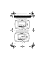
OWNER’S GUIDE
Patents Pending
® U.S. Registered Trademark
© 2004 Honeywell International Inc.
All Rights Reserved
69-1730
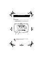
RTH7500D
Programmable Thermostat
The RTH7500D Thermostat provides electronic control of
24 Vac heating and cooling systems or 750 mV heating
systems.
For assistance with your Honeywell product, please visit
www.honeywell.com/yourhome or call Honeywell
Customer Care toll free at 1-800-468-1502.
Read and Save these Instructions
69-1730.fm Page 1 Tuesday, July 13, 2004 12:45 PM

69-1730 2
Contents
Prepare for Installation ............................................................ 3
Follow Important Instructions .................................................. 5
Remove Old Thermostat ......................................................... 6
Follow Special Instructions...................................................... 7
Label Old Thermostat Wires ................................................... 10
Mount New Wallplate to Wall .................................................. 11
Connect Wires to New Wallplate............................................. 15
Install Batteries........................................................................ 23
Attach New Thermostat to Wallplate ....................................... 24
Configure Installer Setup......................................................... 26
Customer Assistance .............................................................. 62
Limited One-Year Warranty..................................................... 63
69-1730.fm Page 2 Tuesday, July 13, 2004 12:45 PM

3 69-1730
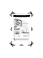
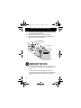
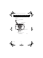
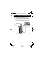
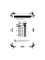
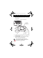
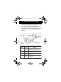
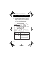
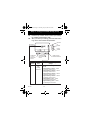
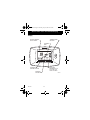
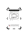
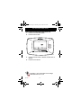
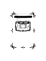
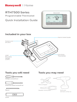
Step 1. Prepare for Installation
1. Check that the following items are included:
If any of the items shown above are missing, call
Honeywell Customer Care at 1-800-468-1502
before returning the thermostat to the store.
CAUTION
TURN OFF POWER to system at the furnace, or at the fuse/circuit
breaker panel before you begin.
Match the letter of
y
our old thermostat wire with the terminal of th
e
correspondin
g
letter on
y
our new thermostat or base
.
Ó
N
e
ll.
co
m
/
y
ou
rh
o
m
e
B
G
R
V
/
V
R
X
B
G
R
V
/
V
R
H
Y2
H
R
C
W
C
L
RH
W1
X2
E
O
T
W2
F
P
U
W3
Y1
F
P
U
W3
Y1
WALLPLATE
THERMOSTAT
M2227
8
MOUNTING SCREWS (2)
AND WALL ANCHORS (2)
OWNER'S GUIDE
CAUTION CARD
WIRE LABELS
M
on
R
ead
a
n
d
sa
v
e
th
ese
in
s
tr
uc
ti
o
n
s
OWNER'S GUIDE
fusibles-interru
p
tor
t
é
69-1730.fm Page 3 Tuesday, July 13, 2004 12:45 PM

69-1730 4
Step 1. Prepare for Installation (Cont)
2. Check that you have everything required for the
installation:
• Two AA alkaline batteries
• No. 2 Phillips screwdriver and standard pocket
screwdriver
•Drill
• Drill bit—use 3/16 in. for drywall; use 7/32 in. for
plaster
• Level (optional)
• Hammer
• Pencil
• Electrical tape
69-1730.fm Page 4 Tuesday, July 13, 2004 12:45 PM

5 69-1730
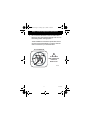
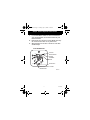
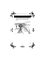
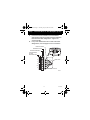
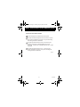
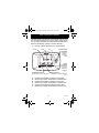
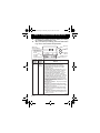
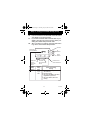
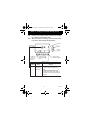
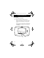
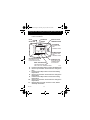
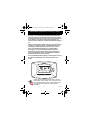
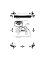
Step 2. Follow Important Instructions
1. Do not connect the wires to the new thermostat
based on wire color because damage can occur to
the heating and/or cooling system.
These Installation Instructions explain later how to
use the enclosed wire labels to correctly mark the
wires connected to your old thermostat.
M22034
Y
G
RC
W
OLD THERMOSTAT
RED
WHITE
YELLOW
ORANGE
GREEN
!
DO NOT WIRE
NEW THERMOSTAT
BASED ON
WIRE COLOR.
R
69-1730.fm Page 5 Tuesday, July 13, 2004 12:45 PM

69-1730 6
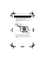
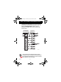
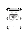
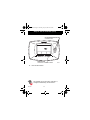
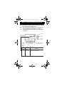
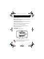
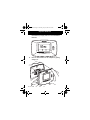
Step 3. Remove Old Thermostat
1. Turn off power at the heating and/or cooling system
or fuse/circuit breaker panel.
2. Remove the cover from the old thermostat.
3. Remove the old thermostat from the wall or wall-
plate. Do not remove the wires.
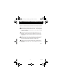
MERCURY NOTICE
If you are replacing a thermostat that contains mercury
in a sealed tube, do not place your old thermostat in the
trash.
Contact your local waste management authority for
instructions regarding recycling and the proper disposal
of an old thermostat containing mercury in a sealed
tube.
Y
G
C
R
W
OLD THERMOSTAT
.1
8
.2
.25
.3
.9
.7
.5
.4
L
O
N
G
E
R
THERMOSTAT
COVER
WALLPLATE
M22036
69-1730.fm Page 6 Tuesday, July 13, 2004 12:45 PM

7 69-1730
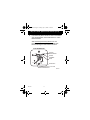
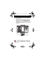
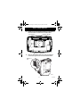
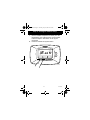
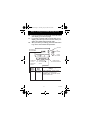
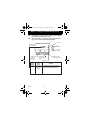
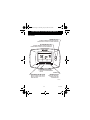
Step 4. Follow Special Instructions
1. If you have two C and/or C1 wires connected to
your old thermostat, do not connect them to your
new thermostat.
2. Disconnect the C and/or C1 wires. Make sure they
do not touch each other or any other wires.
3. Wrap the bare end of each C and/or C1 wire with
electrical tape.
Y
C
C
R
W
OLD THERMOSTAT
WIRE HOLE
M22201
DO NOT CONNECT TO NEW
THERMOSTAT
WIRE
SCREW
TERMINAL
LETTER
DESIGNATION
G
69-1730.fm Page 7 Tuesday, July 13, 2004 12:45 PM

69-1730 8
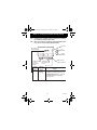
Step 4. Follow Special Instructions (Cont)
4. If you have only one C and/or C1 wire connected to
your old thermostat, connect this wire to C on the
new thermostat.
Visit www.honeywell.com/yourhome or call
Honeywell Customer Care at 1-800-468-1502
before returning the thermostat to the store.
Y
C
R
W
OLD THERMOSTAT
WIRE HOLE
M22223
CONNECT TO THE "C" ON THE
NEW THERMOSTAT
WIRE
SCREW
TERMINAL
LETTER
DESIGNATION
G
69-1730.fm Page 8 Tuesday, July 13, 2004 12:45 PM

9 69-1730
Step 4. Follow Special Instructions (Cont)
5. If you find any wires not connected to your old
thermostat, do not connect them to your new
thermostat.
6. Wrap the end of the wires that are not connected
with electrical tape.
Y
G
R
C
R
OLD THERMOSTAT
WIRE HOLE
WIRES NOT CONNECTED –
DO NOT CONNECT TO
NEW THERMOSTAT
M22040
WIRE
SCREW TERMINAL
LETTER DESIGNATION
W
69-1730.fm Page 9 Tuesday, July 13, 2004 12:45 PM

69-1730 10
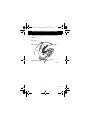
Step 5. Label Old Thermostat Wires
1. As you disconnect each wire, use the enclosed wire
labels to wrap a wire label around each wire that
matches the letter designation. Do not allow the
wires to fall into the wall opening after the wires are
disconnected.
2. Remove any remaining part of the old thermostat
from the wall.
When connecting the wires to the new
thermostat, refer to the wire labels. Do not
connect wires to your new thermostat based on
the color of the wire.
Y
G
R
C
R
OLD THERMOSTAT
WIRE HOLE
M22039
WIRE
SCREW
TERMINAL
LETTER
DESIGNATION
WIRE LABEL
W
W
G
Y
R
RC
69-1730.fm Page 10 Tuesday, July 13, 2004 12:45 PM

11 69-1730
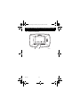
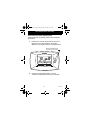
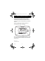
Step 6. Mount New Wallplate to Wall
1. Separate the wallplate from the thermostat as
shown.
THERMOSTAT
WIRE HOLE
M22267
WALLPLATE
69-1730.fm Page 11 Tuesday, July 13, 2004 12:45 PM

69-1730 12
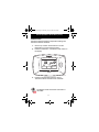
Step 6. Mount New Wallplate to Wall (Cont)
2. Pass the labeled wires through the wire hole on the
wallplate.
M22279
WIRE HOLE
WALL OPENING
WALLPLATE
LABELED WIRES
69-1730.fm Page 12 Tuesday, July 13, 2004 12:45 PM

13 69-1730
Step 6. Mount New Wallplate to Wall (Cont)
3. Position the wallplate on the wall with the arrow
pointing up. Level the wallplate (for appearance
only) and mark the two mounting holes with
a pencil.
M22292
WALLPLATE
LEVEL
PLACE LEVEL ON
SUPPORT TABS
MARK
MOUNTING
HOLES (2)
69-1730.fm Page 13 Tuesday, July 13, 2004 12:45 PM

69-1730 14
Step 6. Mount New Wallplate to Wall (Cont)
4. Move the wallplate aside and drill holes at the
locations marked on the wall. Drill 3/16 in. holes for
drywall or 7/32 in. holes for plaster.
5. Tap the wall anchors into the drilled holes until even
with the wall surface.
6. Position the wallplate over the wall anchors.
7. Insert the mounting screws into the wall anchors.
Check leveling, if desired, and tighten the mounting
screws.
M22293
DRILLED
HOLES (2)
WALL
ANCHORS (2)
MOUNTING
SCREWS (2)
WALLPLATE
69-1730.fm Page 14 Tuesday, July 13, 2004 12:45 PM

15 69-1730
Step 7. Connect Wires to New Wallplate
1. Match the labeled wires to the letter designations
on the wallplate.
2. Select the correct letter designations to follow for
your system. If you have a standard heating and/or
cooling system, use the CONVENTIONAL letter
designations. If you have a heat pump system, use
the HEAT PUMP letter designations to wire the new
thermostat.
See table on page 29 to help you determine if
you have a CONVENTIONAL or HEAT PUMP
system.
M22294
69-1730.fm Page 15 Tuesday, July 13, 2004 12:45 PM

69-1730 16
Step 7. Connect Wires to New Wallplate (Cont)
3. If wires are to be connected to both Rc and R,
loosen the Rc and R screw terminals and remove
the metal jumper wire.
4. If only one of the terminals, Rc or R, is to be
connected, leave the metal jumper wire in place.
M22295
METAL JUMPER WIRE
SCREW TERMINALS
TERMINAL BLOCK
LETTER
DESIGNATIONS
R
RC
Y
G
C
O/B
WALLPLATE
69-1730.fm Page 16 Tuesday, July 13, 2004 12:45 PM

17 69-1730
Step 7. Connect Wires to New Wallplate (Cont)
5. Loosen the screw terminals. Insert the labeled
wires into the holes on the side of the terminal block
that match the letter designations. Tighten the
screw terminals.
6. If any of the labeled wires do not match the letter
designations, see next page for wire connections.
M22325
LABELED WIRES
SCREW TERMINALS
TERMINAL BLOCK
CONVENTIONAL
LETTER
DESIGNATIONS
R
RC
Y
G
C
W
INSERT WIRE IN HOLE
WIRE HOLE
Y
G
WALLPLATE
R
C
R
W
69-1730.fm Page 17 Tuesday, July 13, 2004 12:45 PM

69-1730 18
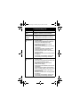
Step 7. Connect Wires to New Wallplate (Cont)
7. Compare letter designations on your old and new
thermostats. Use the information below if you are
wiring a CONVENTIONAL System. Use the
information on page 20 if you are wiring a Heat
Pump system.
Do not connect more than one wire to each
terminal. Be sure to read the notes referenced in
the numbered triangles above. These numbered
notes appear on the next page.
C
G
W
R
RC
or R
CONVENTIONAL
letter designations
on the new thermostat
Possible letter
designations on
the labeled wires
M22208
RC
or RH, 4, V
R
or W1, H
W
or C1, X, B
C
W2
1
2
2
3
1
Y
W2
Y2
or Y1, M
Y
or F
G
Y2
4
69-1730.fm Page 18 Tuesday, July 13, 2004 12:45 PM

19 69-1730
Step 7. Connect Wires to New Wallplate (Cont)
1
M22246
If wires will be connected to both RC and R on the new thermostat,
remove metal jumper wire between R
C and R. Leave metal jumper
wire in place if only one of the terminals, R
C or R, will be connected
on the new thermostat.
If wires were connected to both R and RH terminals on the old
thermostat, remove metal jumper wire between R
C and R on the
new thermostat. Connect the old R to the new R
C and the old RH
to the new R.
If two C and/or C1 wires were connected to the old thermostat, do
not connect them to the new thermostat. Wrap the bare end of
each wire separately with electrical tape and do not use.
If one C and/or C1 wire was connected to the old thermostat, the
wire should be connected to the "C" letter designation on the new
thermostat.
2
3
NOTES FOR CONVENTIONAL HEATING AND COOLING SYSTEMS
4
69-1730.fm Page 19 Tuesday, July 13, 2004 12:45 PM

69-1730 20
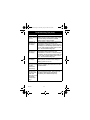
Step 7. Connect Wires to New Wallplate (Cont)
8. Compare letter designations on your old and new
thermostats. Use the information below if you are
wiring a HEAT PUMP system.
Be sure to read the note referenced in the
numbered triangles above. These numbered
notes appear on the next page.
L
C
Y
R
RC
VR or V or
M22210
2
3
3
1
G
AUX
E
R
O
Y
G
C
L
E
W2
O/B
4
H or B,
Y1 or M or
F or
X or B,
F or
X2 or X,
AUX, W1, W or
HEAT PUMP letter
designations on the
new thermostat
Possible letter
designations on
the labeled wires
69-1730.fm Page 20 Tuesday, July 13, 2004 12:45 PM
Page is loading ...
Page is loading ...
Page is loading ...
Page is loading ...
Page is loading ...
Page is loading ...
Page is loading ...
Page is loading ...
Page is loading ...
Page is loading ...
Page is loading ...
Page is loading ...
Page is loading ...
Page is loading ...
Page is loading ...
Page is loading ...
Page is loading ...
Page is loading ...
Page is loading ...
Page is loading ...
Page is loading ...
Page is loading ...
Page is loading ...
Page is loading ...
Page is loading ...
Page is loading ...
Page is loading ...
Page is loading ...
Page is loading ...
Page is loading ...
Page is loading ...
Page is loading ...
Page is loading ...
Page is loading ...
Page is loading ...
Page is loading ...
Page is loading ...
Page is loading ...
Page is loading ...
Page is loading ...
Page is loading ...
Page is loading ...
Page is loading ...
Page is loading ...
-
 1
1
-
 2
2
-
 3
3
-
 4
4
-
 5
5
-
 6
6
-
 7
7
-
 8
8
-
 9
9
-
 10
10
-
 11
11
-
 12
12
-
 13
13
-
 14
14
-
 15
15
-
 16
16
-
 17
17
-
 18
18
-
 19
19
-
 20
20
-
 21
21
-
 22
22
-
 23
23
-
 24
24
-
 25
25
-
 26
26
-
 27
27
-
 28
28
-
 29
29
-
 30
30
-
 31
31
-
 32
32
-
 33
33
-
 34
34
-
 35
35
-
 36
36
-
 37
37
-
 38
38
-
 39
39
-
 40
40
-
 41
41
-
 42
42
-
 43
43
-
 44
44
-
 45
45
-
 46
46
-
 47
47
-
 48
48
-
 49
49
-
 50
50
-
 51
51
-
 52
52
-
 53
53
-
 54
54
-
 55
55
-
 56
56
-
 57
57
-
 58
58
-
 59
59
-
 60
60
-
 61
61
-
 62
62
-
 63
63
-
 64
64


Honeywell RTH9580 User manual
- Category
- Thermostats
- Type
- User manual
- This manual is also suitable for
Ask a question and I''ll find the answer in the document
Finding information in a document is now easier with AI
Related papers
-
Honeywell RET97C Series Touchscreen Programmable Thermostat [RTH7600] User manual
-
-
-
Honeywell RTH7500D Operating instructions
-
-
-
-
-
-
Honeywell RTH5100B User manual
Other documents
-
American Standard ACONT800 Series Owner's manual
-
CTC Union 43168 Owner's manual
-
 Hunter Fan 43168 User manual
-
White Rodgers UNP300 User guide
-
ClimateMaster ATA21H01 Install Manual
-
Trane XT302C User manual
-
 Hunter Fan 44428 Owner's manual
-
 Hunter Fan 44428 User manual
-
 Honeywell Home RTH7560E User manual
-
WarmlyYours TH8321WF1001 Installation guide


