Page is loading ...

AC Power
For Business-Critical Continuity
Npower
™
UPS
Operation & Maintenance Manual–30-130kVA, 60Hz, Single Module System


i
TABLE OF CONTENTS
IMPORTANT SAFETY INSTRUCTIONS . . . . . . . . . . . . . . . . . . . . . . . . . . . . . . . . . . . . . . . . . . . . . . . .1
OVERVIEW OF MANUAL. . . . . . . . . . . . . . . . . . . . . . . . . . . . . . . . . . . . . . . . . . . . . . . . . . . . . . . . .2
1.0 INTRODUCTION . . . . . . . . . . . . . . . . . . . . . . . . . . . . . . . . . . . . . . . . . . . . . . . . . . . . . . . . . .3
1.1 System Description. . . . . . . . . . . . . . . . . . . . . . . . . . . . . . . . . . . . . . . . . . . . . . . . . . . . . . . . . . . 3
1.1.1 Reliability . . . . . . . . . . . . . . . . . . . . . . . . . . . . . . . . . . . . . . . . . . . . . . . . . . . . . . . . . . . . . . . . . . . 4
1.1.2 Versatility . . . . . . . . . . . . . . . . . . . . . . . . . . . . . . . . . . . . . . . . . . . . . . . . . . . . . . . . . . . . . . . . . . . 4
1.2 Safety Precautions . . . . . . . . . . . . . . . . . . . . . . . . . . . . . . . . . . . . . . . . . . . . . . . . . . . . . . . . . . . 4
1.3 Modes Of Operation . . . . . . . . . . . . . . . . . . . . . . . . . . . . . . . . . . . . . . . . . . . . . . . . . . . . . . . . . . 5
1.3.1 Normal (Load On UPS) . . . . . . . . . . . . . . . . . . . . . . . . . . . . . . . . . . . . . . . . . . . . . . . . . . . . . . . . 5
1.3.2 Input Power Failure . . . . . . . . . . . . . . . . . . . . . . . . . . . . . . . . . . . . . . . . . . . . . . . . . . . . . . . . . . . 5
1.3.3 Recharge . . . . . . . . . . . . . . . . . . . . . . . . . . . . . . . . . . . . . . . . . . . . . . . . . . . . . . . . . . . . . . . . . . . . 5
1.3.4 Overload . . . . . . . . . . . . . . . . . . . . . . . . . . . . . . . . . . . . . . . . . . . . . . . . . . . . . . . . . . . . . . . . . . . . 6
1.3.5 Bypass (Internal) . . . . . . . . . . . . . . . . . . . . . . . . . . . . . . . . . . . . . . . . . . . . . . . . . . . . . . . . . . . . . 6
1.3.6 External Maintenance Bypass . . . . . . . . . . . . . . . . . . . . . . . . . . . . . . . . . . . . . . . . . . . . . . . . . . . 6
1.3.7 Off-Battery . . . . . . . . . . . . . . . . . . . . . . . . . . . . . . . . . . . . . . . . . . . . . . . . . . . . . . . . . . . . . . . . . . 6
1.4 Operator Controls. . . . . . . . . . . . . . . . . . . . . . . . . . . . . . . . . . . . . . . . . . . . . . . . . . . . . . . . . . . . 7
1.5 Options . . . . . . . . . . . . . . . . . . . . . . . . . . . . . . . . . . . . . . . . . . . . . . . . . . . . . . . . . . . . . . . . . . . . 7
2.0 THEORY OF OPERATION . . . . . . . . . . . . . . . . . . . . . . . . . . . . . . . . . . . . . . . . . . . . . . . . . . .8
2.1 General Component Description . . . . . . . . . . . . . . . . . . . . . . . . . . . . . . . . . . . . . . . . . . . . . . . . 8
2.1.1 UPS Module . . . . . . . . . . . . . . . . . . . . . . . . . . . . . . . . . . . . . . . . . . . . . . . . . . . . . . . . . . . . . . . . . 8
2.1.2 Battery System . . . . . . . . . . . . . . . . . . . . . . . . . . . . . . . . . . . . . . . . . . . . . . . . . . . . . . . . . . . . . . . 8
2.2 Detailed Component Descriptions . . . . . . . . . . . . . . . . . . . . . . . . . . . . . . . . . . . . . . . . . . . . . . . 9
2.2.1 Controls . . . . . . . . . . . . . . . . . . . . . . . . . . . . . . . . . . . . . . . . . . . . . . . . . . . . . . . . . . . . . . . . . . . . . 9
2.2.2 Rectifier/Charger . . . . . . . . . . . . . . . . . . . . . . . . . . . . . . . . . . . . . . . . . . . . . . . . . . . . . . . . . . . . 10
2.2.3 Battery Charging Circuit . . . . . . . . . . . . . . . . . . . . . . . . . . . . . . . . . . . . . . . . . . . . . . . . . . . . . . 10
2.2.4 Inverter . . . . . . . . . . . . . . . . . . . . . . . . . . . . . . . . . . . . . . . . . . . . . . . . . . . . . . . . . . . . . . . . . . . . 11
2.2.5 Static Bypass Switch . . . . . . . . . . . . . . . . . . . . . . . . . . . . . . . . . . . . . . . . . . . . . . . . . . . . . . . . . 12
3.0 OPERATION . . . . . . . . . . . . . . . . . . . . . . . . . . . . . . . . . . . . . . . . . . . . . . . . . . . . . . . . . . .14
3.1 Operator Controls. . . . . . . . . . . . . . . . . . . . . . . . . . . . . . . . . . . . . . . . . . . . . . . . . . . . . . . . . . . 14
3.1.1 Operator Control Panel . . . . . . . . . . . . . . . . . . . . . . . . . . . . . . . . . . . . . . . . . . . . . . . . . . . . . . . 16
3.1.2 Navigation Buttons . . . . . . . . . . . . . . . . . . . . . . . . . . . . . . . . . . . . . . . . . . . . . . . . . . . . . . . . . . 16
3.1.3 Rotary Switch . . . . . . . . . . . . . . . . . . . . . . . . . . . . . . . . . . . . . . . . . . . . . . . . . . . . . . . . . . . . . . . 17
3.2 Security Access and Passwords . . . . . . . . . . . . . . . . . . . . . . . . . . . . . . . . . . . . . . . . . . . . . . . . 18
3.3 Display Screens and Procedures . . . . . . . . . . . . . . . . . . . . . . . . . . . . . . . . . . . . . . . . . . . . . . . 19
3.3.1 Mimic Display Screen. . . . . . . . . . . . . . . . . . . . . . . . . . . . . . . . . . . . . . . . . . . . . . . . . . . . . . . . . 21
3.3.2 Startup . . . . . . . . . . . . . . . . . . . . . . . . . . . . . . . . . . . . . . . . . . . . . . . . . . . . . . . . . . . . . . . . . . . . 27
3.3.3 Shutdown . . . . . . . . . . . . . . . . . . . . . . . . . . . . . . . . . . . . . . . . . . . . . . . . . . . . . . . . . . . . . . . . . . 33
3.3.4 Status Reports . . . . . . . . . . . . . . . . . . . . . . . . . . . . . . . . . . . . . . . . . . . . . . . . . . . . . . . . . . . . . . 34
3.3.5 Configuration Screens . . . . . . . . . . . . . . . . . . . . . . . . . . . . . . . . . . . . . . . . . . . . . . . . . . . . . . . . 38
3.3.6 Manual Transfer. . . . . . . . . . . . . . . . . . . . . . . . . . . . . . . . . . . . . . . . . . . . . . . . . . . . . . . . . . . . . 56
3.3.7 Battery Management . . . . . . . . . . . . . . . . . . . . . . . . . . . . . . . . . . . . . . . . . . . . . . . . . . . . . . . . . 57
3.3.8 Auto Restart . . . . . . . . . . . . . . . . . . . . . . . . . . . . . . . . . . . . . . . . . . . . . . . . . . . . . . . . . . . . . . . . 66
3.3.9 System Status Monitoring . . . . . . . . . . . . . . . . . . . . . . . . . . . . . . . . . . . . . . . . . . . . . . . . . . . . . 68

ii
3.4 Faults, Alarms, Status . . . . . . . . . . . . . . . . . . . . . . . . . . . . . . . . . . . . . . . . . . . . . . . . . . . . . . . 71
3.4.1 Faults . . . . . . . . . . . . . . . . . . . . . . . . . . . . . . . . . . . . . . . . . . . . . . . . . . . . . . . . . . . . . . . . . . . . . 71
3.4.2 Alarms . . . . . . . . . . . . . . . . . . . . . . . . . . . . . . . . . . . . . . . . . . . . . . . . . . . . . . . . . . . . . . . . . . . . . 72
3.4.3 Status . . . . . . . . . . . . . . . . . . . . . . . . . . . . . . . . . . . . . . . . . . . . . . . . . . . . . . . . . . . . . . . . . . . . . 88
3.5 Communication Interfaces. . . . . . . . . . . . . . . . . . . . . . . . . . . . . . . . . . . . . . . . . . . . . . . . . . . . 88
3.5.1 RS-232 Port: Local Reporting Terminal . . . . . . . . . . . . . . . . . . . . . . . . . . . . . . . . . . . . . . . . . . 89
3.5.2 Worldwide Reporting . . . . . . . . . . . . . . . . . . . . . . . . . . . . . . . . . . . . . . . . . . . . . . . . . . . . . . . . . 89
3.5.3 Remote Alarm Status Panel. . . . . . . . . . . . . . . . . . . . . . . . . . . . . . . . . . . . . . . . . . . . . . . . . . . . 91
3.5.4 SiteScan . . . . . . . . . . . . . . . . . . . . . . . . . . . . . . . . . . . . . . . . . . . . . . . . . . . . . . . . . . . . . . . . . . . 91
3.5.5 Setting Up External Communication Devices . . . . . . . . . . . . . . . . . . . . . . . . . . . . . . . . . . . . . 92
3.6 Modes Of Operation . . . . . . . . . . . . . . . . . . . . . . . . . . . . . . . . . . . . . . . . . . . . . . . . . . . . . . . . . 92
3.6.1 Load on Bypass . . . . . . . . . . . . . . . . . . . . . . . . . . . . . . . . . . . . . . . . . . . . . . . . . . . . . . . . . . . . . . 92
3.6.2 OK to Transfer . . . . . . . . . . . . . . . . . . . . . . . . . . . . . . . . . . . . . . . . . . . . . . . . . . . . . . . . . . . . . . 92
3.6.3 Momentary Overloads . . . . . . . . . . . . . . . . . . . . . . . . . . . . . . . . . . . . . . . . . . . . . . . . . . . . . . . . 93
3.6.4 Input Power Failure (Load on Battery). . . . . . . . . . . . . . . . . . . . . . . . . . . . . . . . . . . . . . . . . . . 93
3.6.5 Automatic Operations . . . . . . . . . . . . . . . . . . . . . . . . . . . . . . . . . . . . . . . . . . . . . . . . . . . . . . . . 94
4.0 MAINTENANCE . . . . . . . . . . . . . . . . . . . . . . . . . . . . . . . . . . . . . . . . . . . . . . . . . . . . . . . . .96
4.1 Safety Precautions . . . . . . . . . . . . . . . . . . . . . . . . . . . . . . . . . . . . . . . . . . . . . . . . . . . . . . . . . . 96
4.2 Routine Maintenance . . . . . . . . . . . . . . . . . . . . . . . . . . . . . . . . . . . . . . . . . . . . . . . . . . . . . . . . 97
4.2.1 Record Log. . . . . . . . . . . . . . . . . . . . . . . . . . . . . . . . . . . . . . . . . . . . . . . . . . . . . . . . . . . . . . . . . . 97
4.2.2 Air Filters . . . . . . . . . . . . . . . . . . . . . . . . . . . . . . . . . . . . . . . . . . . . . . . . . . . . . . . . . . . . . . . . . . 97
4.2.3 Battery Maintenance . . . . . . . . . . . . . . . . . . . . . . . . . . . . . . . . . . . . . . . . . . . . . . . . . . . . . . . . . 97
4.2.4 Battery Safety Precautions . . . . . . . . . . . . . . . . . . . . . . . . . . . . . . . . . . . . . . . . . . . . . . . . . . . . 98
4.2.5 Torque Requirements . . . . . . . . . . . . . . . . . . . . . . . . . . . . . . . . . . . . . . . . . . . . . . . . . . . . . . . . . 99
4.3 Detecting Trouble . . . . . . . . . . . . . . . . . . . . . . . . . . . . . . . . . . . . . . . . . . . . . . . . . . . . . . . . . . 100
4.4 Reporting a Problem. . . . . . . . . . . . . . . . . . . . . . . . . . . . . . . . . . . . . . . . . . . . . . . . . . . . . . . . 100
4.5 Corrective Actions . . . . . . . . . . . . . . . . . . . . . . . . . . . . . . . . . . . . . . . . . . . . . . . . . . . . . . . . . 100
4.6 Recommended Test Equipment . . . . . . . . . . . . . . . . . . . . . . . . . . . . . . . . . . . . . . . . . . . . . . . 100

iii
FIGURES
Figure 1 UPS controls and display screen (with example of the monitor/mimic screen). . . . . . . . . . . . . . . . 6
Figure 2 80 kVA UPS outside and inside views . . . . . . . . . . . . . . . . . . . . . . . . . . . . . . . . . . . . . . . . . . . . . . . 14
Figure 3 Operator control panel . . . . . . . . . . . . . . . . . . . . . . . . . . . . . . . . . . . . . . . . . . . . . . . . . . . . . . . . . . . 15
Figure 4 Navigation buttons . . . . . . . . . . . . . . . . . . . . . . . . . . . . . . . . . . . . . . . . . . . . . . . . . . . . . . . . . . . . . . 16
Figure 5 Rotary switch. . . . . . . . . . . . . . . . . . . . . . . . . . . . . . . . . . . . . . . . . . . . . . . . . . . . . . . . . . . . . . . . . . . 17
Figure 6 Configuration screen. . . . . . . . . . . . . . . . . . . . . . . . . . . . . . . . . . . . . . . . . . . . . . . . . . . . . . . . . . . . . 18
Figure 7 User settings screen, page 6 . . . . . . . . . . . . . . . . . . . . . . . . . . . . . . . . . . . . . . . . . . . . . . . . . . . . . . . 18
Figure 8 Menu tree . . . . . . . . . . . . . . . . . . . . . . . . . . . . . . . . . . . . . . . . . . . . . . . . . . . . . . . . . . . . . . . . . . . . . 19
Figure 9 Main menu screen. . . . . . . . . . . . . . . . . . . . . . . . . . . . . . . . . . . . . . . . . . . . . . . . . . . . . . . . . . . . . . . 21
Figure 10 Monitor / mimic display screen example: normal power flow. . . . . . . . . . . . . . . . . . . . . . . . . . . . . 21
Figure 11 Mimic display screen example: utility fail. . . . . . . . . . . . . . . . . . . . . . . . . . . . . . . . . . . . . . . . . . . . 22
Figure 12 Mimic display screen example: load on bypass, UPS module on and charging battery . . . . . . . . 22
Figure 13 Monitor / mimic display screen example: load on bypass, UPS module off, service mode . . . . . . 23
Figure 14 Mimic display screen detail . . . . . . . . . . . . . . . . . . . . . . . . . . . . . . . . . . . . . . . . . . . . . . . . . . . . . . . 23
Figure 15 Input status screen . . . . . . . . . . . . . . . . . . . . . . . . . . . . . . . . . . . . . . . . . . . . . . . . . . . . . . . . . . . . . . 24
Figure 16 DC bus / battery status . . . . . . . . . . . . . . . . . . . . . . . . . . . . . . . . . . . . . . . . . . . . . . . . . . . . . . . . . . . 24
Figure 17 Bypass input status . . . . . . . . . . . . . . . . . . . . . . . . . . . . . . . . . . . . . . . . . . . . . . . . . . . . . . . . . . . . . 25
Figure 18 Output load status screen. . . . . . . . . . . . . . . . . . . . . . . . . . . . . . . . . . . . . . . . . . . . . . . . . . . . . . . . . 25
Figure 19 Active faults and alarms screen . . . . . . . . . . . . . . . . . . . . . . . . . . . . . . . . . . . . . . . . . . . . . . . . . . . . 26
Figure 20 Active faults and alarms, loss of power . . . . . . . . . . . . . . . . . . . . . . . . . . . . . . . . . . . . . . . . . . . . . . 26
Figure 21 System ratings screen. . . . . . . . . . . . . . . . . . . . . . . . . . . . . . . . . . . . . . . . . . . . . . . . . . . . . . . . . . . . 27
Figure 22 Mimic display screen with load on bypass and switches closed . . . . . . . . . . . . . . . . . . . . . . . . . . . 27
Figure 23 Startup / shutdown procedures screen. . . . . . . . . . . . . . . . . . . . . . . . . . . . . . . . . . . . . . . . . . . . . . . 28
Figure 24 Manual startup screen, close static switch contactors screen . . . . . . . . . . . . . . . . . . . . . . . . . . . . 29
Figure 25 Target and ramp values . . . . . . . . . . . . . . . . . . . . . . . . . . . . . . . . . . . . . . . . . . . . . . . . . . . . . . . . . . 29
Figure 26 DC bus setpoint screen . . . . . . . . . . . . . . . . . . . . . . . . . . . . . . . . . . . . . . . . . . . . . . . . . . . . . . . . . . . 29
Figure 27 External maintenance bypass switch, dual-input UPS . . . . . . . . . . . . . . . . . . . . . . . . . . . . . . . . . 31
Figure 28 External maintenance bypass switch, single-input UPS . . . . . . . . . . . . . . . . . . . . . . . . . . . . . . . . 31
Figure 29 Set number of battery cabinets screen. . . . . . . . . . . . . . . . . . . . . . . . . . . . . . . . . . . . . . . . . . . . . . . 33
Figure 30 User shutdown screen. . . . . . . . . . . . . . . . . . . . . . . . . . . . . . . . . . . . . . . . . . . . . . . . . . . . . . . . . . . . 34
Figure 31 Manual transfer / retransfer screen when transfer is allowed. . . . . . . . . . . . . . . . . . . . . . . . . . . . 34
Figure 32 Manual transfer / retransfer screen when transfer is not allowed . . . . . . . . . . . . . . . . . . . . . . . . 34
Figure 33 Status report screen . . . . . . . . . . . . . . . . . . . . . . . . . . . . . . . . . . . . . . . . . . . . . . . . . . . . . . . . . . . . . 35
Figure 34 Event log report screen showing most recent event. . . . . . . . . . . . . . . . . . . . . . . . . . . . . . . . . . . . 36
Figure 35 Event log report screen showing previous event . . . . . . . . . . . . . . . . . . . . . . . . . . . . . . . . . . . . . . . 36
Figure 36 Event log report screen showing previous event . . . . . . . . . . . . . . . . . . . . . . . . . . . . . . . . . . . . . . . 36
Figure 37 History log metering report screen . . . . . . . . . . . . . . . . . . . . . . . . . . . . . . . . . . . . . . . . . . . . . . . . . 37
Figure 38 History log status report screen . . . . . . . . . . . . . . . . . . . . . . . . . . . . . . . . . . . . . . . . . . . . . . . . . . . . 38
Figure 39 History log faults/alarms report screen . . . . . . . . . . . . . . . . . . . . . . . . . . . . . . . . . . . . . . . . . . . . . . 38
Figure 40 Configuration screen . . . . . . . . . . . . . . . . . . . . . . . . . . . . . . . . . . . . . . . . . . . . . . . . . . . . . . . . . . . . 39
Figure 41 System ratings, page 1 . . . . . . . . . . . . . . . . . . . . . . . . . . . . . . . . . . . . . . . . . . . . . . . . . . . . . . . . . . . 40
Figure 42 System ratings, page 2 . . . . . . . . . . . . . . . . . . . . . . . . . . . . . . . . . . . . . . . . . . . . . . . . . . . . . . . . . . . 40
Figure 43 System settings screen, page 1. . . . . . . . . . . . . . . . . . . . . . . . . . . . . . . . . . . . . . . . . . . . . . . . . . . . . 40
Figure 44 Date setting screen . . . . . . . . . . . . . . . . . . . . . . . . . . . . . . . . . . . . . . . . . . . . . . . . . . . . . . . . . . . . . . 41
Figure 45 Time setting screen . . . . . . . . . . . . . . . . . . . . . . . . . . . . . . . . . . . . . . . . . . . . . . . . . .
. . . . . . . . . . . . 41
Figure 46 System settings, page 2 . . . . . . . . . . . . . . . . . . . . . . . . . . . . . . . . . . . . . . . . . . . . . . . . . . . . . . . . . . 42
Figure 47 System settings, page 3 . . . . . . . . . . . . . . . . . . . . . . . . . . . . . . . . . . . . . . . . . . . . . . . . . . . . . . . . . . 42
Figure 48 Enter password screen . . . . . . . . . . . . . . . . . . . . . . . . . . . . . . . . . . . . . . . . . . . . . . . . . . . . . . . . . . . 42
Figure 49 Single /dual input screen . . . . . . . . . . . . . . . . . . . . . . . . . . . . . . . . . . . . . . . . . . . . . . . . . . . . . . . . . 43

iv
Figure 50 Options screen, page 1 . . . . . . . . . . . . . . . . . . . . . . . . . . . . . . . . . . . . . . . . . . . . . . . . . . . . . . . . . . . 43
Figure 51 10% passive filter settings screen . . . . . . . . . . . . . . . . . . . . . . . . . . . . . . . . . . . . . . . . . . . . . . . . . . 43
Figure 52 Options screen, page 2 . . . . . . . . . . . . . . . . . . . . . . . . . . . . . . . . . . . . . . . . . . . . . . . . . . . . . . . . . . . 44
Figure 53 Options screen, page 3 . . . . . . . . . . . . . . . . . . . . . . . . . . . . . . . . . . . . . . . . . . . . . . . . . . . . . . . . . . . 44
Figure 54 Options screen, page 4 . . . . . . . . . . . . . . . . . . . . . . . . . . . . . . . . . . . . . . . . . . . . . . . . . . . . . . . . . . . 44
Figure 55 Communication options Screen, page 1 . . . . . . . . . . . . . . . . . . . . . . . . . . . . . . . . . . . . . . . . . . . . . . 45
Figure 56 Auto dial screen. . . . . . . . . . . . . . . . . . . . . . . . . . . . . . . . . . . . . . . . . . . . . . . . . . . . . . . . . . . . . . . . . 45
Figure 57 Modem selection screen . . . . . . . . . . . . . . . . . . . . . . . . . . . . . . . . . . . . . . . . . . . . . . . . . . . . . . . . . . 45
Figure 58 Auto dial screen, page 2 . . . . . . . . . . . . . . . . . . . . . . . . . . . . . . . . . . . . . . . . . . . . . . . . . . . . . . . . . . 46
Figure 59 Pager support configuration . . . . . . . . . . . . . . . . . . . . . . . . . . . . . . . . . . . . . . . . . . . . . . . . . . . . . . . 46
Figure 60 Communications options screen, page 2 . . . . . . . . . . . . . . . . . . . . . . . . . . . . . . . . . . . . . . . . . . . . . 47
Figure 61 User settings screen, page 1 . . . . . . . . . . . . . . . . . . . . . . . . . . . . . . . . . . . . . . . . . . . . . . . . . . . . . . . 47
Figure 62 User settings screen, page 2 . . . . . . . . . . . . . . . . . . . . . . . . . . . . . . . . . . . . . . . . . . . . . . . . . . . . . . . 47
Figure 63 User settings screen, page 3 . . . . . . . . . . . . . . . . . . . . . . . . . . . . . . . . . . . . . . . . . . . . . . . . . . . . . . . 48
Figure 64 User settings screen, Page 4. . . . . . . . . . . . . . . . . . . . . . . . . . . . . . . . . . . . . . . . . . . . . . . . . . . . . . . 48
Figure 65 User settings screen, page 5 . . . . . . . . . . . . . . . . . . . . . . . . . . . . . . . . . . . . . . . . . . . . . . . . . . . . . . . 48
Figure 66 10% Passive filter settings screen . . . . . . . . . . . . . . . . . . . . . . . . . . . . . . . . . . . . . . . . . . . . . . . . . . 49
Figure 67 User settings screen, page 6 . . . . . . . . . . . . . . . . . . . . . . . . . . . . . . . . . . . . . . . . . . . . . . . . . . . . . . . 49
Figure 68 Factory settings screen . . . . . . . . . . . . . . . . . . . . . . . . . . . . . . . . . . . . . . . . . . . . . . . . . . . . . . . . . . . 49
Figure 69 Factory settings screen, page 2 . . . . . . . . . . . . . . . . . . . . . . . . . . . . . . . . . . . . . . . . . . . . . . . . . . . . 50
Figure 70 Factory settings screen, page 3 . . . . . . . . . . . . . . . . . . . . . . . . . . . . . . . . . . . . . . . . . . . . . . . . . . . . 50
Figure 71 Alarm / fault name screen . . . . . . . . . . . . . . . . . . . . . . . . . . . . . . . . . . . . . . . . . . . . . . . . . . . . . . . . 51
Figure 72 Alarm edit screen . . . . . . . . . . . . . . . . . . . . . . . . . . . . . . . . . . . . . . . . . . . . . . . . . . . . . . . . . . . . . . . 51
Figure 73 Customer alarm interface screen . . . . . . . . . . . . . . . . . . . . . . . . . . . . . . . . . . . . . . . . . . . . . . . . . . . 53
Figure 74 Customer alarm interface screen, page 2 . . . . . . . . . . . . . . . . . . . . . . . . . . . . . . . . . . . . . . . . . . . . 53
Figure 75 Programmable output relay board #1, AS400 assignment . . . . . . . . . . . . . . . . . . . . . . . . . . . . . . 53
Figure 76 Relay assignments . . . . . . . . . . . . . . . . . . . . . . . . . . . . . . . . . . . . . . . . . . . . . . . . . . . . . . . . . . . . . . 53
Figure 77 Programmable output relay board, standard set . . . . . . . . . . . . . . . . . . . . . . . . . . . . . . . . . . . . . . 54
Figure 78 Programmable output relay board, standard set, page 2 . . . . . . . . . . . . . . . . . . . . . . . . . . . . . . . . 54
Figure 79 Programmable output relay board, user defined . . . . . . . . . . . . . . . . . . . . . . . . . . . . . . . . . . . . . . 54
Figure 80 List of alarm faults screen . . . . . . . . . . . . . . . . . . . . . . . . . . . . . . . . . . . . . . . . . . . . . . . . . . . . . . . . 55
Figure 81 Manual transfer / retransfer screen when transfer is allowed. . . . . . . . . . . . . . . . . . . . . . . . . . . . 56
Figure 82 Manual transfer / retransfer screen when transfer is not allowed . . . . . . . . . . . . . . . . . . . . . . . . 57
Figure 83 Battery management screen. . . . . . . . . . . . . . . . . . . . . . . . . . . . . . . . . . . . . . . . . . . . . . . . . . . . . . . 57
Figure 84 Battery test screen . . . . . . . . . . . . . . . . . . . . . . . . . . . . . . . . . . . . . . . . . . . . . . . . . . . . . . . . . . . . . . 57
Figure 85 Automatic test screen . . . . . . . . . . . . . . . . . . . . . . . . . . . . . . . . . . . . . . . . . . . . . . . . . . . . . . . . . . . . 58
Figure 86 Set battery cycle screen . . . . . . . . . . . . . . . . . . . . . . . . . . . . . . . . . . . . . . . . . . . . . . . . . . . . . . . . . . 59
Figure 87 Set battery duration screen . . . . . . . . . . . . . . . . . . . . . . . . . . . . . . . . . . . . . . . . . . . . . . . . . . . . . . . 59
Figure 88 Battery equalizer screen. . . . . . . . . . . . . . . . . . . . . . . . . . . . . . . . . . . . . . . . . . . . . . . . . . . . . . . . . . 60
Figure 89 Auto screen . . . . . . . . . . . . . . . . . . . . . . . . . . . . . . . . . . . . . . . . . . . . . . . . . . . . . . . . . . . . . . . . . . . . 60
Figure 90 Manual screen . . . . . . . . . . . . . . . . . . . . . . . . . . . . . . . . . . . . . . . . . . . . . . . . . . . . . . . . . . . . . . . . . . 60
Figure 91 Equalize time period screen . . . . . . . . . . . . . . . . . . . . . . . . . . . . . . . . . . . . . . . . . . . . . . . . . . . . . . . 60
Figure 92 Equalize voltage screen . . . . . . . . . . . . . . . . . . . . . . . . . . . . . . . . . . . . . . . . . . . . . . . . . . . . . . . . . . 61
Figure 93 Battery temperature compensation charge screen . . . . . . . . . . . . . . . . . . . . . . . . . . . . . . . . . . . . . 61
Figure 94 Battery temperature compensation enable/disable screen. . . . . . . . . . . . . . . . . . . . . . . . . . . . . . . 61
Figure 95 Battery temperature compensation charge screen, page 2. . . . . . . . . . . . . . . . . . . . . . . . . . . . . . . 62
Figure 96 Battery temp compensation edit screen. . . . . . . . . . . . . . . . . . . . . . . . . . . . . . . . . . . . . . . . . . . . . . 62
Figure 97 Battery cycle monitor screen . . . . . . . . . . . . . . . . . . . . . . . . . . . . . . . . . . . . . . . . . . . . . . . . . . . . . . 62
Figure 98 Battery cycle monitor screen, page 2 . . . . . . . . . . . . . . . . . . . . . . . . . . . . . . . . . . . . . . . . .
. . . . . . . 63
Figure 99 0-30 seconds discharge cycles . . . . . . . . . . . . . . . . . . . . . . . . . . . . . . . . . . . . . . . . . . . . . . . . . . . . . . 63

v
Figure 100 Summary page screen. . . . . . . . . . . . . . . . . . . . . . . . . . . . . . . . . . . . . . . . . . . . . . . . . . . . . . . . . . . . 64
Figure 101 User settings, page 2. . . . . . . . . . . . . . . . . . . . . . . . . . . . . . . . . . . . . . . . . . . . . . . . . . . . . . . . . . . . . 65
Figure 102 Battery time low warning screen. . . . . . . . . . . . . . . . . . . . . . . . . . . . . . . . . . . . . . . . . . . . . . . . . . . 65
Figure 103 Auto restart setting screen . . . . . . . . . . . . . . . . . . . . . . . . . . . . . . . . . . . . . . . . . . . . . . . . . . . . . . . . 66
Figure 104 Auto restart screen layout . . . . . . . . . . . . . . . . . . . . . . . . . . . . . . . . . . . . . . . . . . . . . . . . . . . . . . . . 66
Figure 105 System status screen . . . . . . . . . . . . . . . . . . . . . . . . . . . . . . . . . . . . . . . . . . . . . . . . . . . . . . . . . . . . 67
Figure 106 System status screen, page 2 . . . . . . . . . . . . . . . . . . . . . . . . . . . . . . . . . . . . . . . . . . . . . . . . . . . . . . 68
Figure 107 System status screen, page 3 . . . . . . . . . . . . . . . . . . . . . . . . . . . . . . . . . . . . . . . . . . . . . . . . . . . . . . 68
Figure 108 System status screen, page 4 . . . . . . . . . . . . . . . . . . . . . . . . . . . . . . . . . . . . . . . . . . . . . . . . . . . . . . 68
Figure 109 Summary alarm in active position screen . . . . . . . . . . . . . . . . . . . . . . . . . . . . . . . . . . . . . . . . . . . . 71
Figure 110 Summary alarm editing screen . . . . . . . . . . . . . . . . . . . . . . . . . . . . . . . . . . . . . . . . . . . . . . . . . . . . 72
Figure 111 Pager support screen . . . . . . . . . . . . . . . . . . . . . . . . . . . . . . . . . . . . . . . . . . . . . . . . . . . . . . . . . . . . 89
Figure 112 Load on bypass, UPS not available . . . . . . . . . . . . . . . . . . . . . . . . . . . . . . . . . . . . . . . . . . . . . . . . . 91
Figure 113 Load on bypass (UPS available and battery charging). . . . . . . . . . . . . . . . . . . . . . . . . . . . . . . . . . 91
Figure 114 Utility fail, load on battery . . . . . . . . . . . . . . . . . . . . . . . . . . . . . . . . . . . . . . . . . . . . . . . . . . . . . . . . 92
TABLES
Table 1 Key locations on UPS . . . . . . . . . . . . . . . . . . . . . . . . . . . . . . . . . . . . . . . . . . . . . . . . . . . . . . . . . . . . 14
Table 2 Key locations on operator control panel. . . . . . . . . . . . . . . . . . . . . . . . . . . . . . . . . . . . . . . . . . . . . . 15
Table 3 External maintenance bypass switch positions and actions . . . . . . . . . . . . . . . . . . . . . . . . . . . . . 32
Table 4 External maintenance switch configuration options . . . . . . . . . . . . . . . . . . . . . . . . . . . . . . . . . . . 32
Table 5 Default time settings . . . . . . . . . . . . . . . . . . . . . . . . . . . . . . . . . . . . . . . . . . . . . . . . . . . . . . . . . . . . 58
Table 6 Abbreviations used in alarm messages . . . . . . . . . . . . . . . . . . . . . . . . . . . . . . . . . . . . . . . . . . . . . . 72
Table 7 Alarms, functions, and corrective actions . . . . . . . . . . . . . . . . . . . . . . . . . . . . . . . . . . . . . . . . . . . . 73
Table 8 Service terminal command summary . . . . . . . . . . . . . . . . . . . . . . . . . . . . . . . . . . . . . . . . . . . . . . . 88
Table 9 Battery voltage record . . . . . . . . . . . . . . . . . . . . . . . . . . . . . . . . . . . . . . . . . . . . . . . . . . . . . . . . . . . 97
Table 10 Circuit breakers with compression lugs (for power wiring) . . . . . . . . . . . . . . . . . . . . . . . . . . . . . . 97
Table 11 Terminal block with compression lugs (for control wiring) . . . . . . . . . . . . . . . . . . . . . . . . . . . . . . 97
Table 12 Recommended test equipment and tools . . . . . . . . . . . . . . . . . . . . . . . . . . . . . . . . . . . . . . . . . . . . . 98

vi

1
IMPORTANT SAFETY INSTRUCTIONS
SAVE THESE INSTRUCTIONS.
This manual contains important instructions that should be followed during maintenance of your
Npower UPS and batteries.
!
WARNING
Exercise extreme care when handling UPS cabinets to avoid equipment damage or injury to
personnel. Refer to separate installation manual for equipment handling information and
installation procedures.
Follow all battery safety precautions in 4.0 - Maintenance when installing, charging, or
servicing batteries. In addition to the hazard of electric shock, gas produced by batteries can
be explosive and sulfuric acid can cause severe burns.
In case of fire involving electrical equipment, use only carbon dioxide fire extinguishers or
others approved for use in electrical fire fighting.
Extreme caution is required when performing maintenance.
Be constantly aware that the UPS contains high DC as well as AC voltages. With input power
off and the battery disconnected, high voltage at filter capacitors and power circuits should be
discharged within 30 seconds. However, if a power circuit failure has occurred, you should
assume that high voltage may still exist after shutdown. Check with a voltmeter before
making contact.
AC voltage will remain on the system bypass, the UPS output terminals and the static bypass
switch, unless associated external circuit breakers are opened.
Check for voltage with both AC and DC voltmeters prior to making contact.
When the UPS system is under power, both the operator and any test equipment must be
isolated from direct contact with earth ground and the UPS chassis frame by using rubber
mats.
Some components within the cabinets are not connected to chassis ground. Any contact
between floating circuits and the chassis is a lethal shock hazard. Exercise caution that the
test instrument exterior does not make contact either physically or electrically with earth
ground.

2
OVERVIEW OF MANUAL
The Npower manual is organized so that information can be found quickly. Each major topic is sepa-
rated by sections, and there is a Table of Contents for each section. The names of the sections and
their contents are described below.
Section 1 - INTRODUCTION is a summary of the Npower Uninterruptible Power System (UPS). It
describes some of the unique features and benefits of the Npower UPS, as well as the design princi-
ples and standards that Liebert follows in the manufacture of each system. A description of the
Npower system and an overview of its functions are also included.
Section 2 - THEORY OF OPERATION is an explanation of the major circuit groups of the Npower
UPS. This section is for individuals who want to know both the basics and the specifics of each major
component. The text explains how the UPS handles electrical disturbances and interruptions.
Section 3 - OPERATION is written for facility personnel responsible for the operation of the system.
It details the procedures required to start-up the system, to transfer the load between the available
sources, and to shut down the system. Both manual and automatic operations are described. Operator
controls and displays, including the solid state liquid crystal display (LCD) screen, are illustrated and
explained for the UPS Module.
Section 4 - MAINTENANCE lists routine maintenance checks and helps the Operator pinpoint and
quickly resolve problems if they arise.
If you require assistance for any reason, call Liebert Global Services at 1-800-LIEBERT. For best ser-
vice, please have the following information available:
Part Numbers:
Serial Numbers:
kVA Rating:
Date Purchased:
Date Installed:
Location:
Input Voltage:
Output Voltage:
Battery Reserve Time:

Introduction
3
1.0 INTRODUCTION
1.1 System Description
The role of the UPS system is to supply uninterruptible, clean power to the critical load. It maintains
a full-voltage, low-distortion output, even if the utility source power sags or becomes distorted.
If there is an outage of the source power, the UPS maintains power to the load until an alternate
source of power is activated, or until the original power source is restored. If input AC power is not
restored, the UPS maintains the load (with the battery plant) long enough that the critical equipment
can be shut down in an orderly manner. The Npower UPS module displays the rate of battery dis-
charge and calculates the amount of battery time remaining based on the actual connected load. The
time that the battery will maintain the load depends on the capacity of the battery backup plant and
the size of the load.
The system control logic automatically manages critical bus operation. System logic is resident in Dig-
ital Signal Processors (DSPs) for precise control and improved reliability.
If the critical load current exceeds the rated load of the Npower UPS system, the control logic deter-
mines the magnitude of the overload and reacts appropriately. Overloads are usually the result of
inrush current requirements. The UPS system supports loads that are 150% of the rated load for up
to 60 seconds, 125% of the rated load for up to ten minutes, and 104% of the rated load indefinitely.
If the load surpasses the overload capacity of the UPS, the load is automatically transferred to bypass
without interruption. When the load returns to within the UPS rating, it is either automatically or
manually returned (retransferred) to the UPS. How and when the load is returned to the UPS
depends on several factors: how long the overload lasted, how many overload conditions occurred
before transfer, whether there is an imminent failure of any part of the UPS, etc. In the unlikely
event of a fault within the UPS, the control logic, which continuously monitors all critical circuits
within the UPS system, transfers the load to bypass without interruption and simultaneously sets off
local and remote alarms. For a few specified faults, the UPS is shut down. The UPS can be manually
returned to service when the fault has been corrected.
The Npower UPS display system provides precise monitoring of the UPS, fast alarm response, and
quick troubleshooting. For easy manual operations, menu-driven software provides access to several
step-by-step help screens. All operator functions are performed using menu-prompted displays and a
minimum number of operator controls. Available options include external communication capability
with both automatic dial-out and dial-in features for early warning and diagnosis of abnormal condi-
tions.
The system software allows the operator or Liebert Global Services to enter application specific infor-
mation. Overload, overvoltage, battery discharge, and shutdown limits can be set by the operator. In
effect, the software is tailored for each site.
The UPS system protects critical equipment from source power disturbances and outages, load faults,
and UPS malfunctions. This triple protection virtually eliminates computer and computing equip-
ment downtime as a result of utility source power problems.

Introduction
4
1.1.1 Reliability
Reliability is the most important design goal for Uninterruptible Power Systems. All Liebert 3-Phase
UPS systems have demonstrated reliability by achieving a field-proven critical bus MTBF in excess of
one million hours. In addition, our Quality Assurance program is certified to the requirements of ISO
9001 standards.
Liebert UPS systems are ETL listed to the requirements of UL 1778, CSA Certified and (when appli-
cable) CE marked. All equipment and components are manufactured to applicable UL, NEC, IEC,
EN, NEMA, ANSI, IEEE, EN50091-1, EN50091-2 and CSA standards and guidelines.
Designed For Success
The keys to reliability in the design of the UPS system are using conservatively rated components,
minimizing transfers to bypass, making operator controls understandable, and providing easy access
for maintenance and repair. Liebert UPS systems lead the industry in all these areas.
For example, the Npower can clear substantial overloads through the solid state static bypass switch
without transferring to the bypass source. By minimizing transfers to bypass, the Npower mini-
mizes operation of electrical components and enhances system reliability.
As mentioned above, the system control logic has been packaged into Digital Signal Processors (DSPs)
to optimize system performance and eliminate the failure-prone discrete logic boards used in other
brands of UPS products. Furthermore, these DSPs are isolated from heat-generating components to
ensure optimal operating temperatures.
Factory Backup and Service Assistance
Reliability depends on more than just UPS module design. Improper installation can cause any sys-
tem to fail. To prevent this, service technicians from Liebert Global Services thoroughly inspect the
installation of all our systems to ensure they are installed properly and operating within performance
specifications.
Once a UPS is properly installed, you -- the on-site equipment operator -- are the most important fac-
tor in preventing critical bus failures or unplanned transfers to bypass. To make your task easier, the
UPS provides easy-to-follow, prompted instructions on its operator display screen.
If you ever need help, call your Liebert distributor or sales representative. Your attention to proper
installation, operation, and periodic maintenance will ensure that your mission-critical operations
receive the best possible protection from electrical disturbances and outages.
1.1.2 Versatility
The Npower has a number of features and options that can be customized to your specific needs. See
1.5 - Options for details. Visit the battery manufacturer’s Web site for information on obtaining the
manual if you don’t already have it.
1.2 Safety Precautions
Read this manual thoroughly, paying special attention to the sections that apply to you, before work-
ing with the UPS. Also read the battery manufacturer's manual before working on or near the bat-
tery.
Under typical operation and with all UPS doors closed, only normal safety precautions are necessary.
The area around the UPS system and battery should be kept free from puddles of water, excess mois-
ture, or debris.
Special safety precautions are required for procedures involving handling, installation, and mainte-
nance of the UPS system or the battery. Observe precautions in the separate Installation Manual
before handling or installing the UPS system. Observe precautions in 4.0 - Maintenance of this
manual before and during performance of all maintenance on the UPS or battery.
This equipment contains several circuits that are energized with high voltage. This is particularly
true for oscilloscopes. Always check with an AC and DC voltmeter to ensure safety before making con-
tact or using tools. Even when the power is turned Off, dangerously high potentials may exist at the
capacitor banks. Observe all battery precautions when near the battery for any reason.

Introduction
5
ONLY qualified service personnel should perform maintenance on the UPS system. When performing
maintenance with any part of the equipment under power, service personnel and test equipment
should be standing on rubber mats. The service personnel should wear insulating shoes for isolation
from direct contact with the floor (earth ground).
Unless all power is removed from the equipment, one person should never work alone. A second per-
son should be standing by to assist and summon help in case an accident should occur. This is partic-
ularly true when work is performed on the battery.
Three types of messages are used throughout the manual to stress important text. Carefully read the
text below each Warning, Caution, and Note and use professional skills and prudent care when per-
forming the actions described by that text.
A Warning signals the presence of a possible serious, life-threatening condition. For example:
A Caution indicates a condition that could seriously damage equipment and possibly injure personnel.
For example:
A Note emphasizes important text. If the note is not followed, equipment could be damaged or may
not operate properly. For example:
1.3 Modes Of Operation
Refer to 2.0 - Theory of Operation and 3.0 - Operation for more details.
1.3.1 Normal (Load On UPS)
The utility AC source provides power to the rectifier/charger in the UPS module. The rectifier/charger
converts the utility AC power to DC and supplies DC power to the UPS module inverter while simul-
taneously float charging the battery plant. The UPS inverter converts DC to AC and furnishes AC
power to the critical bus.
1.3.2 Input Power Failure
If the utility source power fails or is outside the acceptable range, the battery plant becomes the pri-
mary supplier of DC power to the inverter.
1.3.3 Recharge
After the utility source power is restored, or an alternate power source becomes available, the recti-
fier/charger slowly walks-in to once again power the inverters and recharge the battery plant.
!
WARNING
Lethal voltages may be present within this unit even when it is apparently not operating.
Observe all cautions and warnings in this manual. Failure to do so could result in serious
injury or death. Do not work on or operate this equipment unless you are fully qualified to do
so! Never work alone.
!
CAUTION
Make sure you understand the proper sequence before operating any circuit breaker.
Operating a Maintenance Bypass circuit breaker out of sequence could cut off power to the
critical load.
NOTE
If the UPS system has a blown fuse, the cause should be determined before you replace the fuse.
Contact Liebert Global Services.

Introduction
6
1.3.4 Overload
Overloads in critical systems may be caused by inrush currents during connected equipment startup
or by faults in the critical load or distribution network. The Liebert Npower UPS system can maintain
full output voltage regulation while sustaining the following overloads:
• Up to 125% for 10 minutes
• Up to 150% for 1 minute
• Up to 200% for 10 cycles
For momentary faults above 200% of rated current, the static switch turns on for 10 cycles to supply
power from the bypass source. Up to 6,000 amps of current can be supplied for the first half cycle.
The critical load remains on the UPS module for the above conditions. If the UPS system overload
capacity is exceeded, an automatic transfer to bypass is initiated, which keeps the static switch on
and opens the inverter output contactor.
Whenever you have an overload condition, you should determine the cause of the overload.
1.3.5 Bypass (Internal)
The UPS control logic initiates an automatic transfer to the bypass source if the overload-current-ver-
sus-time curve is exceeded or if specified UPS system faults occur. You can also manually transfer the
load to the bypass (without interruption) if you must take the UPS module out of service for mainte-
nance.
With the rotary switch in the Bypass position, most key components and operating modes can be
checked without disturbing the critical bus. However, certain key power-carrying components will
require complete system shutdown or isolation through an external maintenance bypass cabinet for
100% service.
1.3.6 External Maintenance Bypass
The installation of an External Maintenance Bypass Cabinet or panel board is recommended to allow
you to totally isolate the UPS from all power sources. Use of the External Maintenance Bypass is
described in SIB External Maintenance Bypass on page 30.
1.3.7 Off-Battery
The battery plant can be disconnected from the rectifier/charger by using an external Module Battery
Disconnect (MBD) circuit breaker. The UPS continues to function normally, though it does not have
power outage back-up capability until the battery plant is reconnected.
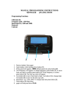
Figure 1 UPS controls and display screen (with example of the monitor/mimic screen)
MIMIC DISPLAY
SYS. STATUS
BATTERY
INV.
LOAD
RECT.
SS
CHG

Introduction
7
1.4 Operator Controls
Liebert Npower UPS modules are equipped with a microprocessor-based Operator Display Screen and
Control Panel designed for convenient and reliable operation. The front panel location of the monitor-
ing and control system enables the Operator to quickly identify the current status of the UPS and to
perform most of the manual operations.
The operator display screen is driven by an easy-to-follow menu-prompted software program that con-
trols and monitors the UPS system.
Detailed instructions on how to interpret the displays and use the controls are in 3.0 - Operation.
1.5 Options
A number of standard pre-designed options are available from Liebert for your UPS system.
Described below are the most frequently provided options. Note that the battery items (1 and 2) are
required to complete the UPS system. The remaining options provide improved system performance
or convenience.
1. Battery and Racks. The batteries provide power in the event of a power outage. The Liebert UPS
can use a variety of battery types, provided the battery plant is designed for the UPS DC voltage
range and the load requirements of your application.
2. Module Battery Disconnect. The UPS system utilizes a separate Module Battery Disconnect for
remotely located batteries. A sensing circuit in the UPS module, set at the battery low voltage
limit, trips the Module Battery Disconnect to safeguard the battery from excessive discharge. The
Module Battery Disconnect has an undervoltage release mechanism designed to ensure that
during any shutdown or failure mode all battery potential is removed from the UPS system.
3. Input Distortion Filter (Trap). This filter reduces input current reflected harmonic distortion to
less than 10% THD at full load. The filter is factory installed within the UPS. This filter also
improves the input power factor to better than 0.95 lagging.
4. Load Bus Synchronization (LBS). The Load Bus Sync (LBS) option keeps two independent UPS
modules (and therefore their critical load buses) in sync, even when the modules are operating on
batteries or asynchronous AC sources. This means that critical loads connected to both load buses
can switch seamlessly between the two.
5. SiteScan Central Monitoring System. Liebert manufactures a central monitoring system that
automatically displays key UPS measurements and alarms, as well as data from a variety of
sensors. This monitoring system signals alarms so corrective action can be taken. Events and
data can be printed in hard copy. Data can be logged for analysis. The SiteScan Interface port is
standard for the Npower.
6. Remote Alarm Status Panel. The UPS system may also be provided with an optional Remote
Alarm Status Panel. This Panel provides eight LED indicators and may be placed at a convenient
location near the critical load. A functional description of the Remote Alarm Status Panel is
provided in 3.5.3 - Remote Alarm Status Panel.
7. Open Comms - Discrete Output Option OC-DO (Programmable Relay Board). Each option has 8
channels. Up to two Programmable Relay options can be installed in the same UPS. Any alarm/
event can be programmed onto any channel or channels. Programming is performed through the
LCD display. Each relay channel has two sets of Form-C dry contacts rated 1 Amp @ 30 VDC or
250 mAmp @ 125 VAC.
8. Open Comms - Discrete Input Option OC-DI (Input Contact Isolator). Provides UPS module
interface for up to eight user relay inputs (normally open dry contacts) for user alarm messages.
The user through the LCD display can program the UPS alarm messages. The input alarm can
also be installed to trigger an Open Comms - Discrete Output Option channel. Each alarm can
have auto-dial, event log, and time delay (0 to 999.9 seconds).
9. Optional Power Supply (OPS). An additional control power supply is required when a Remote
Alarm Status Panel and/or three or more battery circuit breakers are present in the system.
10. Internal Modem. Provides a 2400-baud modem in the UPS capable of dialing out from the UPS or
accepting incoming calls and connecting to a remote terminal, computer or PC. A command set
allows the user to view the alarm status, event log status, history status and system settings. The
modem can also be configured to dial out two different telephone numbers, a primary and a
backup number as a result of a significant UPS event. The selection of dial-out events is
programmable by the Operator.
11. Network Interface Card - NIC. This option provides internal hardware and software to
communicate (via SNMP and HTTP) to any I.P.-based Ethernet network. Connection to the
network is made by a 10 baseT Ethernet cable provided by the user.

Theory of Operation
8
2.0 THEORY OF OPERATION
2.1 General Component Description
The UPS system includes all of the equipment necessary to continuously provide computer- grade AC
power to a critical load, even when there is an interruption of the utility line power. It consists of the
UPS modules and a back-up battery plant. Refer to Figure 2.
2.1.1 UPS Module
The UPS module consists of system controls, a rectifier/charger, an inverter, protective devices, and
other accessories.
System Controls: The system control logic automatically manages critical bus operation and monitors
performance of the UPS module. Microprocessor technology and dedicated firmware provide advanced
logic control and a comprehensive display of information. The UPS module status is displayed locally.
Optional ports permit communicating with external devices.
Rectifier/Charger: The rectifier/charger converts utility power from AC to DC to charge the battery
and provide the DC input to the inverter. Its design limits reflected harmonic current distortion to
source power and provides low-ripple DC power for charging batteries.
Inverter: The inverter converts DC power into the precise AC power required to supply a sensitive
critical load. The inverter converts DC power into a pulse-width-modulated (PWM) that is easily fil-
tered into a clean sine wave output. The PWM also minimizes the harmonic voltage distortion caused
by typical switching power supplies and other nonlinear load components used in computers and
related electronics.
Static Bypass Switch: The static (solid-state) bypass switch immediately transfers the load from the
inverter to the bypass AC power source in the event of a severe overload on the system or a failure
within the UPS. This transfer takes place without any interruption of the power supplied to the load.
The system includes redundant circuits to detect and isolate shorted SCRs in the static switch.
Bypass Circuit: The bypass circuit consists of switches and associated synchronizing and control cir-
cuitry to transfer the load to/from the bypass source.
2.1.2 Battery System
The battery is used as the alternate source of power to supply DC power to the inverter if the AC sup-
ply voltage is outside the acceptable range. The battery supplies power to the inverter until the utility
power is restored or until an alternate power source is available. If AC source power is not restored or
an alternate power source is not available, the battery can be sized to provide power long enough for
an orderly shutdown of the load.

Theory of Operation
9
2.2 Detailed Component Descriptions
2.2.1 Controls
Hardware
The Npower UPS operator interface display system is designed to provide all of the information that
is required for the operation of each UPS module. The following is a list of the hardware features:
1. The control logic performs automatic operations with minimal operator interface. The limited
number of manual controls are easy-to-use.
2. Each Npower UPS cabinet is equipped with an easy-to-read liquid crystal display (LCD) screen. It
presents information in a way that is easy to understand at an eye-level front panel location.
3. The display is controlled by a dedicated microprocessor with a non-volatile (EPROM) program
and a battery-backed event memory.
4. The Npower can be ordered with communication ports for:
a. Transmission of present status information to remote terminals via a resident auto-dial
communications program and an external or optional internal modem. This port also
responds to inquiries of the UPS and history from the remote terminal.
b. Reporting UPS and history information in response to inquiries from a local terminal (no
modem required).
c. Reporting information to a Liebert SiteScan Central Monitoring System.
d. Relaying selected alarm messages to a Liebert Remote Alarm Status Panel and to a separate
terminal board for customer use.
e. Reporting key systems information via SNMP interface to a network monitoring system.
Firmware
The operator interface display system software enables the operator to monitor the UPS system sta-
tus, to control the power flow through the UPS, to monitor all of the meter readings, to execute the
start-up, shutdown, and the load transfer procedures, to access the event history files, and to make
adjustments to the programmable parameters. The following is a list of the firmware features:
1. The menu-driven software prompts the operator for input.
2. Step-by-step instructions assist the operator during the start-up, shutdown, and the load transfer
procedures. This helps to eliminate operator errors.
3. Graphics-based mimic diagrams illustrate the position of internal switches and the power flow
through the UPS system.
4. The Present Status screen reports information about the system's present status. The History
Status screen chronicles the events leading up to and immediately after a fault. The Event
History screen lists all of the alarm messages that have been logged over a period of time.
Refer to 3.0 - Operation for a description of the controls and indicators located on the Operator Con-
trol Panel.
NOTE
All external communication devices are optional equipment.

Theory of Operation
10
2.2.2 Rectifier/Charger
The UPS module rectifier/charger consists of input fuses, AC current-limiting circuit, battery equalize
charge circuit, DC filter, battery charge-current-limiting circuit, and bridge rectifiers.
Operation
The rectifier/charger converts the AC input power to DC power. This conversion is accomplished by 3-
phase bridge rectifiers using SCRs. All phases are individually fused. For all modules, reflected input
current THD is less than 30% at full load (which may be reduced to less than 10% with optional fil-
ter).
The filtered output of the rectifier/charger provides regulated DC power to drive the inverter and
charge the battery.
Input
The input is sized to allow enough current to recharge the battery and supply a full-rated load at the
same time.
Input Current Limit
AC input current sensing transformers (CTs) are used to measure current levels. Control circuitry
monitors the CTs and restricts the AC current to less than 125% of the full input current rating by
reducing the battery charging voltage. This current limit is adjustable from 100 to 125% of the system
capacity measured in AMPS, with the default setting at 125% (maximum AMPS). An external dry
contact closure (field supplied) activates a reduced second level of the battery charge current limiting
circuit for use with a back-up generator.
Input Current Limit, Second Level
A second level of input current limit is initiated by an external contact closure (field supplied for use
with back-up generator), and is adjustable from 85 to 100% (factory set at 100%).
During a rectifier re-start following battery discharge, the current slowly ramps up (walks-in) from
20% of the rated input current to 100% over a 15 to 20 second period. The maximum rate of change of
the AC input current is 15% per second. The input current walk-in reduces the start-up surge distor-
tion effects on all other equipment connected to the same source and prolongs the service life of inter-
nal components.
Input Current Inrush
The maximum sub-cycle of inrush current is typically less than 6-8 times normal.
Input Power Factor
The rated input power factor is no less than 0.80 lagging at the nominal input voltage and the full
rated UPS load. The optional input filter will improve the power factor to better than 0.92 lagging at
full load. Refer to drawings for your specific model.
2.2.3 Battery Charging Circuit
The UPS module charging circuit is capable of recharging the battery plant to 95% of full capacity
within 10 times the discharge time. Recharging the last 5% takes longer because of characteristics
inherent in the battery. DC ripple voltage is limited to 0.5% RMS to preserve battery life during long-
term float charging while the UPS system is operating on utility source power.
Operation After Discharge
When commercial power is interrupted, the battery continues to supply DC power to the inverter
without interruption to the critical load. If the AC source power is restored before the battery has
fully discharged, the rectifier automatically restarts and resumes carrying the inverter and battery
recharge load requirements.

Theory of Operation
11
Operation After End-of-discharge
The battery time screen displayed on the control panel enables you to estimate when battery shut-
down will occur. You will have enough time to energize an alternate AC power source or to initiate an
orderly shutdown of the critical load. If the battery plant discharges to the shutdown point during an
outage, the UPS automatically disconnects the load, the AC input, and the battery. After AC input
power is restored, the rectifier can be manually restarted by the Operator.
Battery Disconnect
The module battery disconnect (MBD) circuit breaker is used to isolate the UPS module from the bat-
tery during maintenance, and to automatically disconnect the battery from the inverter at the end of
battery discharge. The MBD circuit breaker must be closed manually unless you have the optional
motorized battery breaker. (See 3.3.8 - Auto Restart).
Battery Charge Current Limiting
The battery recharge current, after a battery discharge, is limited to between 1 and 25% (adjustable)
of the full load maximum discharge current stated in AMPS. This regulates the amount of current
that flows from the power source to the battery while the battery is recharging.
The battery charge current limit is factory set at one-half of maximum or 12.5% for normal operation
and at 1% for alternate power source recharge operation.
Battery Equalize Charge Circuit
The battery equalize charge feature can be manually initiated or it can be programmed to operate
automatically. Either can be selected from the battery equalize screen displayed on the control panel.
The automatic battery equalizing charge circuit increases the rectifier/charger output voltage to
charge the battery anytime there is a power outage of 30 seconds or longer. The equalizing voltage is
slightly higher than the float voltage. This helps all the batteries in a string to reach a uniform state
of charge.
2.2.4 Inverter
The inverter is a solid state device that converts the DC output of the rectifier/charger or the battery
to AC power.
Operation
The inverter converts DC power from either the battery or the rectifier/charger into three pulse-
width-modulated/six-step waveforms. These waveforms are filtered into low-distortion sine wave
power. The inverter is controlled by a Digital Signal Processor (DSP). This DSP controls the precise
synchronization, amplitude, and frequency of the output voltage.
In addition to the inverter efficiently supplying a regulated AC output from a DC source, the inverter
output provides isolation between the critical load bus and the commercial source power. The inverter
is configured to handle most critical load inrush surges. It maintains output voltage Total Harmonic
Distortion (THD) within specifications even when handling nonlinear computer loads.
Output Regulation and Overload Performance
The inverter is capable of sustaining full output voltage (±1% of the nominal voltage) for up to 150%
overload at the output for as long as 60 seconds without reducing the output voltage. It can also han-
dle at least 125% of the rated current for up to 10 minutes. If an overload exceeds the system capacity
and a bypass source is available, the critical load is transferred to the bypass source and the inverter
is disconnected from the load.
NOTE
The manufacturers of the valve-regulated batteries supplied with Liebert’s standard battery
cabinets recommend that when first installed the batteries be equalize charged. After that
initial equalize charge, they recommend no further equalize charging for their batteries. Other
manufacturers may have different recommendations for their products. Consult the battery
manufacturer’s manual for specific information about equalize charging.

Theory of Operation
12
Nonlinear Load Characteristics
Computers and computer equipment with switching power supplies generate nonlinear currents rich
in fifth and seventh harmonics.
The inverter pulse-width-modulated waveform, coupled with the output filter, provides a natural
path for reducing the fifth and seventh harmonic currents produced by the load. The inverter/filter
limits the output voltage THD to less than 3% with up to 100% typical electronic data processing
(EDP) loads. EDP equipment characteristically includes both nonlinear and linear load components.
Unbalanced Load Characteristics
Unbalanced loads are actively regulated. The phase-to-phase voltage balance is maintained to within
2%, even with a 50% load imbalance.
2.2.5 Static Bypass Switch
A static bypass switch is an integral part of the UPS. An automatic transfer control circuit senses the
status of the operator controls, UPS logic signals and alarm messages, and critical bus operating con-
ditions. If the inverter output can no longer supply the critical load, the static bypass switch automat-
ically transfers the critical load to the bypass source without interruption.
Static Switch Backfeed Protection
The static bypass system is equipped with redundant disconnect circuits that prevent backfeed of
lethal voltage to the bypass input in the event of a shorted static switch SCR. If a shorted SCR is
detected, the static bypass switch is isolated and an alarm is annunciated at the UPS control panel,
while the critical load remains on UPS output power.
Pulsed Parallel Operation
When an overload condition such as magnetic inrush current or a branch load circuit fault exceeds
200% of the full-load current rating, the static bypass switch pulses on for 10 cycles. This allows up to
6000 amperes from the bypass line to clear the overload without a complete transfer to bypass (a Lie-
bert design exclusive). The bypass source is in parallel with the UPS system, permitting the bypass
source to carry the initial overload current. If the overload clears before 10 cycles, a load transfer to
bypass is not made. If the overload condition continues to exceed the inverter capacity, the automatic
transfer is made (maintaining the load voltage within the specified limits).
Load Transfers
Transfers to (transfer) or from (retransfer) the bypass may be performed automatically or manually in
a make-before-break (MBB) sequence.
Manual load transfers and retransfers are initiated by the Operator from the UPS Control Panel.
Automatic transfers are initiated by the UPS system control logic when an overload is beyond the
specified capabilities of the UPS inverter or when a fault occurs within the UPS module. An auto-
matic retransfer is initiated if this function is enabled and if system conditions for a retransfer are
present.
/