Page is loading ...

INSTALLATION INSTRUCTIONS
Fan Heater
Model No.
Contents
General Safety Inf rmation
Description
Unpacking
Supplied Accessories
Dimensions
Wiring Diagram
Installation
Operating instructions
Maintenance
Practical Guide to Installation
Specifications
Product Service
o
Important Instructions
2
2-4
5
6
7-11
Back cover
Back cover
Back cover
5
5
6
12
12
READ AND SAVE THESE INSTRUCTIONS
Thank you for purchasing this Panasonic product.
Please read these instructions carefully before attempting to install,operate or service
the Panasonic product. Failure to comply with instructions could result in personal injury
or property damage. Please explain to users how to operate and maintain the product
after installation, and this booklet should be presented to users.
Please retain this booklet for future reference.
FV-07VFH3

GENERAL SAFETY INFORMATION
For Your Safety
To reduce the risk of injury, loss of life, electric shock, fire,malfunction, and damage to
equipment or pro always observe the following safety precautions.
Explanation of symbol word panels
The following symbol word panels are used to classify and describe the level of hazard,
injury, and property damage caused when the denotation is disregarded and improper
use is performed.
WARNING
WARNING
Denotes a potential hazard that could result in
serious in jury or death.
CAUTION
Denotes a hazard that could result in minor injury.
Denotes a hazard that could result in property
damage.
The following symbols are used to classify and describe the type of instructions to be observed.
Read all instructions before installing or using this fan heater.
This symbol is used to alert users to a specific operating procedure that must
not be performed.
This symbol is used to alert users to a specific operating procedure that must be
followed in order to operate the unit safely.
IMPORTANT INSTRUCTIONS
Make sure that the electric service supply voltage is AC 120V, 60Hz.
Always disconnect the power source before working on or near the fan, motor
or junction box.
This product must be properly grounde .d
Do not operate any heater after it malfunctions. Disconnect power at service
panel and have heater inspected by a reputable electrician before reusing.
Use this heater only as described in this manual. Any other use not recommended
by the manufacturer may cause fire, electric shock, or injury to persons.
Before servicing or cleaning unit, switch power off at service panel and lock panel
cabinet to prevent power from being switched on accidentally. If the panel
cabinet cannot be locked, securely fasten a clearly visible warning label to the
service panel.
2
Installation work and electrical wiring must be done by qualified person(s) in
accordance with all applicable codes and standards, including fire-rated
construction. Neither unauthorized modification,repair nor disassembly is allowed.
NOTICE

CAUTION
A heater has hot and arcing or sparking parts inside. Do not use it in areas where
gasoline,paint, or flammable vapors or liquids are used or stored.
IMPORTANT INSTRUCTIONS CONTINUED
Use only on 20 ampere branch circuit.
Do not disassemble the unit for reconstruction. It may cause fire or electric shock.
Never place a switch where it can be reached from a tub or shower.
Do not install with a method which is not approved in the instructions.
Do not use out doors.
To prevent a possible fire, do not block air intakes or exhuast in any manner.
A statement to the effect that when the product is to no longer be used, it must
not be left in place but removed, to prevent it from possibly falling.
3
Do not install this fan heater where air temperature may exceed 40°C(104°F) .
To reduce the risk of fire, electric shock or injury to persons, observe the following:
Use this unit only in the manner intended by the manufacturer. If you have
any questions, please contact the manufacturer.
When cutting or drilling into wall or ceiling, do not damage electrical wiring
and other hidden utilities.
Ducted fans must always be vented to the outdoors.
Celiling joist must be subjected to static load more than five times the weight
of the product.
The special-purpose or dedicated parts, such as mounting fixtures, must be used if
such parts are provided.
Follow all local electrical and safety codes, as well as the National Electrical Code
(NEC) and the Occupation Safety and Health Act (OSHA).
This heater is hot when in use. To avoid burns, do not let bare skin touch hot
surfaces. Keep combustible materials, such as furniture, pillows, bedding, papers,
clothes, etc. and curtains at least 3 feet(0.9m) from the front of the heater and
keep them away from the sides and rear.
Not to be installed in a ceiling thermally insulated to a value greater than R40.
(This is required for installation in Canada only.)
WARNING

Do not insert or allow foreign objects to enter any ventilation or exhaust opening
as this may cause an electric shock or fire, or damage the heater.
Do not install the unit where ducts are configured as shown in Fig. A.
Make sure that all duct work is properly vented.
Before cleaning, make sure the power has been turned off at the circuit breaker
panel and that the heating element of the heater is cool.
Prohibition
Prohibition Prohibition
Fig.A
Prohibition
Adaptor
IMPORTANT INSTRUCTIONS CONTINUED
Not for use in cooking area.(Fig.B).
4
Fig.B
(Cooking area)
Do not install above or
inside this area
Cooking
equipment
Floor
45
45
Solid state controls may cause harmonic distortion which can cause motor
humming noise. To reduce the risk of fire or electric shock, do not use this unit
with any solid-state control device.
CAUTION
UNPACKING
Unpack and carefully remove unit from carton.
Refer to the Supplied Accessories list to verify that all parts are present.
The Panasonic Fan Heater is specially developed for bathroom heating. It uses a sirocco
fan driven by a capacitor motor. The motor is designed to have an extended service life
with reduced energy consumption. It also incorporates a thermal cut-off for safety. The
louver covering the main body is screw-fixed type. A dumper driven by a gear motor is
designed to shift the heating and vent functions. A shutter for preventing counter-flow
is provided. The blower uses a high capacity sirocco fan to reduce noise level.
The heater for this unit is a 1300W PTC heater. A thermostat and thermal cut-off switch
have been added for safety in case of an abnormal temperature rise in the heater.
DESCRIPTION

Install
plate L
Install plate
R
Hanger holder
Installation
Instnuctions
Warranty
card
Adapter
1
1
1
1
2
1
1
2
12
Screw Ⅱ
(ST4.2X10)
Long screw
( X30)ST4.2
Switch
labels
SUPPLIED ACCESSORIES
Part name Part name
Appearance Appearance
Quantity Quantity
Louver
1
1
1
Suspension
bracket Ⅰ
3
5
Suspension
bracketⅡ
Screw Ⅰ
(M4x8)
DIMENSIONS
Unit:inches(mm)
Aperture dimensions: 10 x10 inches(270x270mm)
4
10
3
2
10
No. No.
Part name Part name
Louver
Adaptor
Unit body
Heater assembly
Air outlet grille
Screw cap
Airproof shutter
Hanger unit
Inspection cover
1
5
2
6
3
7
Cord cover
4
8
9
1
8
9
(20)
5 (147)
4 (107)
( 98)
7
5
6
11 (295)
3"
5
4"
5
3"
5
3"
5
4"
5
4"
1"
5
12 (320)
3"
5
12 (320)
3"
5
10 (260)
1"
4
13 (346)
3"
5
10 (260)
1"
4
11 (295)
3"
5
6 (160)
3"
10
6 (160)
3"
10

6
WIRING DIAGRAM
INSTALLATIONⅠ(BETWEEN JOIST MOUNTING)
Top view of the recommended installation.
1.Make a hole of 10 10 inch(270
270mm in the ceiling between j ist.(Fig.1)
X X
o
2.Assemble the hanger unit
Insert the suspension
and put the adaptor
(Fig.2)
brackets into hanger
holder into the hanger
holder.
The bathroom size may affect the
room heating result of this product.
10 (270)
10 (270)
Fig.2
Fig.1
Suspension brackets
Hanger
holder
Adaptor
Unit:inches(mm)
Wall
Air duct
Product
Bathroom
Bathtub
63(1600)
31 (800)
17
(450)
Unit:inches(mm)
1"
2
3"
4
3"
5
3"
5
3
"
5
3"
5

INSTALLATIONⅠ(BETWEEN JOIST MOUNTING)
7
16 inches and
19.2 inches
horizontal joist
19.2 inches
vertical joist
A
B
19.2 inches vertical joists
19.2 inches horizontal joists
16 inches
Spacing A on center joists
Unit:inches (mm)
B
13 1/4 15 1/2(336 394)
~ ~
14 3/4 16 3/4(374 425)
~ ~
16 1/2 18 3/4(419 476)
~ ~
3.Fix the hanger unit to the ceiling.
(1) Using 1 of the ST4.2X30 tapping screws
provided accessory package to fix
the hanger unit to the ceiling.
in the
(Fig.3)
(2) Using 4 of the ST4.2X30 tapping screw
provided accessory package to fix
the suspension brackets to the joist .
s
in the
s
(Fig.4)
Fig.3
Fig.4
Joist
Circular duct
Duct tape
① Take out the cord cover and stress relief
two knockout holes.(Fig.5)
Cord cover
Knock-out hole
INSTALLATION JOIST MOUNTING-Ⅰ) CONTINUEDⅠ(BETWEEN
5. The connection of power wire and control
lead wire.
4. Slip the circular duct onto the adaptor and
secure it with duct tape.(Fig.4)
Control lead wires(4 wires)
Conduit
Power wires
(3 wires)
Fig.6
WARNING:
1.Wiring procedures and connections shall
be in accordance with the national and
local electrical codes having jurisdiction.
2.This product must be properly grounded.
Fig.5
② Secure conduits, pass house power wires
and control lead wires througth the holes.
(Fig.6)

Red to
wall switch
Blue to
wall switch
Brown to
wall switch
Green to earth
ground
Wire nut
White to neutral
Black to live
INSTALLATION JOIST MOUNTING-Ⅰ) CONTINUEDⅠ(BETWEEN
③ Refer to wiring diagram (Page.6) or Fig.9,
follow all the local electrical safety codes.
As well as the National Electrical code
(NEC),Using UL approved wire nuts,
connect house power wires and control
lead wires to product wires.(Fig.7)
Make sure all connections are fastened
firmly after wiring is finished.
8
For future inspection by qualified persons,
put the lead wires into the hook after
connection work.
④
(Fig.8)
Fig.7
Fig.8
Wire nut
Control
lead wines
Power
wires
Hook
HEAT/VENT
Fig.9
From red wire
From blue wire
From brown wire
(wall switch)
Green wire
White
ON/OFF
Black
E
N
L
Green
⑤ Fix the cord cover with the screws that
taken off at step1.
1. Disconnect power source before working
on unit.
2. When making wiring connections take
care to prevent excessive slack in the
wiring since a layge of current is drawn
through the heater electrical wire.
3. To reduce the risk of fire, do not store or
use gasoline or other flammable vapors
and liquids in the vicinity of the heater
WARNING
1.High temperature, risk of fire, keep electrical
cords, drapery,furnishings, and other
combustibles at least 3 feet (0.9 m) from the
front of the heater and away from the side
and rear.
2.Mount the cord cover carefully so that lead
wires are not pinched.
CAUTION
6. Main body fixed.
Push the main body upward into the ceiling,
use 4 of the ST4.2X30self-tapping screws
provided in the accessory package to fix it.
(Fig.10)
7.Install plate fixed.
Insert the install plates into the main body
jockey for position(one of each side), use the
ST4.2X10 self-tapping screws provided in the
accessory package to fix them. (Fig.11)
Fig.10
Fig.11

9.Install plates locked.
Using 2 of the ST4.2X30 self-tapping screws
provided in the accessory package to lock the
install plates (Fig.13),make sure the screws are
go through the hole of install plates,and the
drywall is clampped tightly.(Fig.14)
8.Use one of the ST4.2X30 self-tapping srews
in the accesso y package to fix the
and the hanger unit.(Fig.12)
provided r
product frame
9
Fig.12
Fig.13
INSTALLATION JOIST MOUNTING-Ⅰ) CONTINUEDⅠ(BETWEEN
Drywall
Fig.14
③ Insert a straight screw driver into the gap
of the screw cap (2 positions), and unclench
the screw cover outward.(Fig.17)
9.Louver fixed
① Pull out the filter mesh from the louver
assembly.(Fig.15)
② Hang the louver into the hook on the main
body.(Fig.16)
Main body hook
Fig.15
Fig.16
Fig.17

④ Fix the louver assembly with the 3 of the
M4X8 mechanical screws in the accessory.
(Fig.18)
10
INSTALLATION JOIST MOUNTING-Ⅰ) CONTINUEDⅠ(BETWEEN
⑤ Install the filter mesh again and attach the
unclenched screw caps again.(Fig.19)
10.Paste the switch label provided in the
accessory package on the switch panel.
s
(Fig.20)
[Optional]
Attach the given switch labels (in accessories)
on the wall switch (not included) as shown in
the diagram for clearer indication.(Fig.20)
Switch
labels
On
Heat
Off
Vent
Fig.20
Screw caps(2 pcs)
Fig.18
Fig.19
INSTALLATION Ⅱ(JOIST MOUNTING)
1. Make a hole of 10 X 10 inches (270 X
270mm) adjacent to a joist.(Fig.21)
2. Assemble the hanger unit.
Put the adaptor into the hanger holder.
(Fig.22)
3. Fix the hanger unit to the ceiling.
(1) Using 1 of the ST4.2X30 tapping screws
provided accessory package to fix
the hanger unit to the ceiling.
(2)
in the
(Fig.23)
Using 2 of the ST4.2X30 tapping screws
provided in the accessory package to fix
the hanger unit to the joist.(Fig.24)
4.Slip the circular duct onto the adaptor and
secure it with duct tape.(Fig.24
Joist
Duct
tape
Circular
duct
Adaptor
Hanger
holder
Fig.21
Fig.22
Fig.23
Fig.24
3"
5
10 (27
0)
3
"
5
1
0 (2
70
)
3"
5
3"
5

5.Follow step 5 of installation Ⅰ(page 8) to
complete the connection of power wires and
control lead wires.
6.Main body fixed.
Push the main body upward into the ceilling,
use 4 of the ST4.2X30 self-tapping screws
provided in the accessory package to fix it.
7.Follow step 7,8,9,10 of installation
(Fig.25 & Fig.26 )
Ⅰ(page 9-
10) to complete the install plate fixed,install
plate locked,louve fixed and paste the switch
labels.
INSTALLATION Ⅱ(JOIST MOUNTING)
11
Fig.25
Joist
Fig.26
OPERATING INSTRUCTIONS
1.Fan heater is in STOP stage when switch is set
as shown in Fig.27.The unit is not operated
in this stage.
2.Fan heater is in HEAT mode when switch is set
as ahown in Fig.28.The unit blown out hot air.
The bathroom become warm.
3.Fan heater is in VENT mode when switch is set
as shown in Fig.29.
Fresh air is caming into bathroom.
On
Heat
Off
Vent
On
Heat
Off
Vent
On
Heat
Off
Vent
Fig.27 Fig.28 Fig.29
The heater shall be properly installed before
it is used.
WARNING
1.Never use petrol, benzene, thinner or any other
such chemicals for cleaning the ventilating fan.
2.Do not allow any water to get into the motor.
3.Do not soak resin parts in water over 60°C(140°F).
CAUTION:
MAINTENANCE (CLEANING)
Disconnect power source before working on unit.
Routine maintenance must be done every year.
WARNING:
Before cleaning, make sure the power has been
turned off at the circuit breaker panel and that the
heating element of the heater is cool.
Fig.30
① Pull out the filter mesh assembly as shown
in the figure (Fig.30).

MAINTENANCE (CLEANING)
③ Install the assembly again filter mesh (Fig.32).
② Remove the . And vacuum-clean, wash
and dry
filter mesh
(Fig.31).
Fig.31
Fig.32
Model No.
Air direction
Voltage
(V)
Frequency
(Hz)
Power consumption (W)
Air deliver
Noise
Heat Vent
Vent (0.1" WG)
(cfm)
Vent
(sone)
Weight
Ib.(kg)
FV-07VFH3
Exhaust &
Circulation
Specifications of Vent are based on HVI standard.
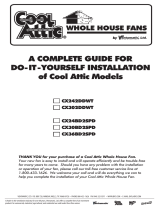
Dryer-hood type vent with
backdraft flap (s).
Caulk termination to duct.
2-3 ft straight run before elbow.
In attic installation,
caulk box to drywall.
Short piece of flexible duct
helps alignment and absorbs
sound. Use clamps plus tape
at all flex joints.
Insulation
Foil tape tightly covers all metal
dust joints (glue PVC joints).
PRACTICAL GUIDE TO INSTALLATION
Properly insulate the area around
the fan to minimize building heat
loss and gain. 3)
(Fig.
Loose fill or batt insulation can be
placed directly over the fan housing
in the attic.
3
SPECIFICATIONS
120
60
26
70
1.5
3.6
PRODUCT SERVICE
Warning Concerning Removal of Covers.
The unit should be serviced by qualified technicians only.
Your product is designed and manufactured to ensure a minimum of maintenance.
Should your unit require service or parts,call panasonic Call Center at 1-866-292-7292 (USA)
or 1-800-669-5165 (Canada).
X0113-0 07VFH34200
1346(25 C)
Fig.33
1/12