Page is loading ...


•
TANDY COMPUTER PRODUCTS
TANDY 1000
HX
TECHNICAL REFERENCE MANUAL
Cat. No. 25-1513

.
TANDY COMPUTER PRODUCTS -
Tandy 1000
HX
Technical Reference Manual
Copyright 1987, Tandy Corporation.
All Rights Reserved.
Reproduction
or
use
of any
portion
of
this manual without
express written permission from Tandy Corporation and/or
its
licensor,
is
prohibited. While reasonable efforts have been
taken
in
the preparation
of
this manual
to
assure
its
accuracy, Tandy Corporation assumes
no
liability resulting
from any errors
in or
omissions from this manual,
or
from
the use
of the
information obtained herein.

•
TANDY COMPUTER PRODUCTS -
Tandy 1000 HX
Technical Reference Manual
Contents
Sections
Main Logic Board
Devices
Power Supply
Keyboard
Disk Drive
Options
Important Customer Note:
A gray stripe has been printed along the right edge
of the title page of each of the sections to
facilitate your finding the beginning of the
section. Also,
a
tabbed divider for each section
has been provided for insertion at this point.

•
TANDY COMPUTER PRODUCTS
1000
HX
Main Logic Board

•
TANDY COMPUTER PRODUCTS
1000 HX Main Logic Board
Contents
Section Page
Introduction
1
Specifications
3
Connector Pin Assignments
4
Option Card Description
8
Bus Interface Specifications
13
Signal Listing
13
System Timing
17
Theory of Operation
21
Main Logic Board
21
CPU Function
21
Non-CPU Function, Main Logic Board
21
Processor Address/Data Interface
21
CPU Control Signal Generation
24
IFL Equations
25
System Control Signal Generation
25
Bus Specification
25
Interrupt Function
28
Bus Interface
30
Keyboard/Timer/Sound Timer Circuits
30
Keyboard Interface
30
Timer Function
32
Sound Function
32
Joystick Interface
35
Printer Interface
35
Floppy Disk Controller Interface
38
Video System Logic
39
Main System Board RAM Timing
42
I/O Map Summary
45
Video/System Memory Address Map
62
Schematic Diagrams
63

.
TANDY COMPUTER PRODUCTS
INTRODUCTION
TO
THE TANDY 1000
HX
COMPUTER
The Tandy 1000
HX
Computer
is
modular
in
design
to
allow
maximum flexibility
in
system configuration. The computer
consists
of a
Main Unit, and
a
monitor. The Main Unit
is
supplied with one
3
1/2" internal disk drive.
A
second
internal
3
1/2" disk drive
is
optional. Each disk drive
has
a capacity
of
720K bytes formatted. The standard types
of
monitors used with the Tandy 1000
HX
are the monochrome
composite and the color RGB monitor.
The Tandy 1000
HX
has
a
standard 256K
of
system RAM.
An
optional DMA/RAM board allows the Tandy 1000
HX to be
expanded
by
128K
or
384K
of
RAM. This board will fit onto
the expansion slot. With
a
fully populated RAM board
installed, the Tandy 1000
HX
will have 640K bytes
of
RAM
allowed
by
the system memory map.
Other features include
a
parallel printer port, two built-in
joystick interfaces, and
a
headphone connection for private
listening.
The Main Unit
is
the heart
of
the Tandy 1000 HX.
It
houses
the Main Logic Assembly, system power supply,
internal
3
1/2" disk drive, and keyboard.
The Main Logic Assembly
is a
large board mounted
to
the
bottom of the Main Unit and interconnected
to
the keyboard,
power supply, and disk drive
by a
series
of
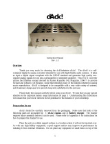
cables. Figure
1
shows the Tandy 1000
HX.
The Power Supply
is a
28W switching regulator type, designed
to provide adequate power capacity for
a
fully configured
system.
The Internal
3
1/2" Disk Drive uses double-sided,
double-density diskettes
to
read, write,
or
store data.
These are soft sector diskettes. The Disk Drive assembly
is
installed
in
the standard unit. All system programs, with
the exception
of
the system startup sequence, are stored
on
disk.

•
TANDY COMPUTER PRODUCTS
Either
a
monochrome
or a
color display may
be
used with
the
Tandy 1000 HX. The monochrome monitor
is a
high-resolution
green phosphor display which provides excellent visual
quality.
It
features
a
12" screen with
an
anti-glare
surface.
Each display
is
capable
of 25
lines
of 80
characters.
The character matrix
is 8
wide
x 9
high.
Figure 1. TANDY 1000
HX

TANDY COMPUTER PRODUCTS
SPECIFICATIONS
Processor: Intel 8088-2
Dimensions:
3
1/4
x 17 x 14 1/2
(HWD)
Weight:
11
lbs
Power Requirements: 120 VAC,
60 Hz
With
3
1/2" Disk Drives, Memory Cards, and RS-232:
AC Current:
0.7 -
0.8 Amps with Floppy doing R/W tests.
Leakage Current: 0.5
mA
Power Supply Output:
+5 VDC 3.0 Amps max.,
1.9
Amps Typ.
+12 VDC 2.0 Amps max. 1.2 Amps continuous
-12 VDC .1 Amp max.
Environment:
Air Temperature
System ON:
55 to 85
degrees
F
(13
to
30 degrees
C)
System OFF: -40
to
150 degrees
F (-40 to 69
degrees
C)
Humidity: System ON-OFF:
8% to
80%
Disk Drive Specifications
Power:
Supply
Voltage
+5
VDC Input
Ripple
0 to 50 kHz 0.1 Vpp
Tolerance
Including Ripple
+/-5%
Standby Current
Nominal 50
mA
Average Current
(Read)
Peak Current
(Motor Start)
Peak Current
(Stepping during Motor
On)
Operating Current
Nominal 240
mA
+12
0.1
0.3
130
500
450
VDC Input
Vpp
mA
mA
mA
mA

•
TANDY COMPUTER PRODUCTS
Connector Pin Assignments
Jl
—
J2
—
J3
—
Speaker Interface
(2-Pin Vertical Header)
1
—
Sound
PWR
f
NUM
f
CAP
1
—
Power Indicator
3
—
Num Indicator
5
—
CAPS Indicator
Keyboard Interface
J4
—
1
—
2
—
3
—
4
—
5
—
6
—
Fan
1
—
XI
X5
X4
X3
X2
X6
+12V
2
—
Ground
2
—
Gnd
4
—
NUMLOCK Control
6
—
CAPS Control
7
— XO
8
— X7
9
— X3
10
— XI
11
— X5
12
— X4
2
—
GND
J5
— DC
POWER
(6-Pin Vertical Header)
1
—
+5 VDC
3
—
GND
5
—
+12V
J6
—
Keyboard Interface
1
— Y0
2
— Yl
3
—
Yll
4
— Y2
5
— Y3
6
— Y4
7
— Y5
J7
—
Audio Jack
1
—
GND
2
4
6
8
9
10
11
12
13
— +5 VDC
— Ground
12V
—
Y6
—
Y7
—
Y8
—
Y9
— Y10
— Yll
2
—
AUDIOOUT

•
TANDY COMPUTER PRODUCTS
J8
—
Right Joystick
(6-Pin Rt. Angle Circular Din)
1
— Y
Axis
2 — X
Axis
3
—
Ground
4 —
Switch
1
5
— +5
VDC
6 —
Switch
2
J9
—
Left Joystick
(6-Pin Rt. Angle Circular Din)
1
— Y
Axis
2 — X
Axis
3
—
Ground
4 —
Switch
1
5
— +5
VDC
6 —
Switch
2
J10
— 3
1/2" Disk Interface Internal
(Dual 17-Pin Vertical Header)
1
3
5
7
9
11
13
15
17
19
21
23
25
27
29
31
33
—
NC
— +5
V.
— +5
V.
— +5
V.
— +5
V.
— +5
V.
— Ground
— Ground
— Ground
— Ground
— Ground
— Ground
— Ground
— Ground
— +12
V.
— +12
V.
— +12
V.
2
4
6
8
10
12
14
16
18
20
22
24
26
28
30
32
34
—
NC
—
NC
—
NC
— INDEX*
— DSO
— DS2
—
NC
— MTRON*
— DIR*
— STEP*
— WRDATA*
— WEN*
— TRKO*
— WRPRT*
— RDDATA*
— SIDESELECT*
—
NC

.
TANDY COMPUTER PRODUCTS
Jll
—
Expansion Interface Connectors
(Dual 31-Pin Header)
A01
A02
A03
A04
A05
A06
A07
A08
A09
A10
All
A12
A13
A14
A15
A16
A17
A18
A19
A20
A21
A22
A23
A24
A25
A26
A27
A28
A29
A30
A31
—
NMI
—
D7
—
D6
—
D5
—
D4
—
D3
--
D2
—
Dl
—
DO
—
RDYIN
—
AEN
—
A19
—
A18
—
A17
—
A16
—
A15
—
A14
—
A13
—
A12
—
All
—
A10
—
A09
—
A08
—
A07
—
A06
—
A05
—
A04
—
A03
—
A02
—
A01
—
A00
B01
B02
B03
B04
B05
B06
B07
B08
B09
BIO
Bll
B12
B13
B14
B15
B16
B17
B18
B19
B20
B21
B22
B23
B24
B25
B26
B27
B28
B29
B30
B31
—
Ground
—
RESET
—
+5
VDC
—
IR2
—
NC
—
FDCDMRQ*
12
VDC
—
NC
—
+12
VDC
—
Ground
—
MEMW*
—
MEMR*
—
IOW*
—
IOR*
—
NC
—
NC
—
NC
—
NC
—
REFRESH*
—
CLK
—
RFSH
—
BREQ*
—
NC
—
IR4
—
IR3
—
FDCDACK*
—
DMATC
—
ALE
—
+5 VDC
—
OSC
—
Ground

TANDY COMPUTER PRODUCTS
J12
--
J13
—
J14
—
J15
—
Parallel Interface
(34-Edge Card)
1
—
PPSTROBE*
3
—
PPDATAO
5
—
PPDATAl
7
—
PPDATA2
9
—
PPDATA3
11
—
PPDATA4
13
—
PPDATA5
15
—
PPDATA6
17
—
PPDATA7
19
—
PPACK*
21
—
PPBUSY
23
—
PPE
25
—
PPSEL*
27
—
PPAUTOF*
29
— NC
31
—
Ground
33
—
Ground
2
—
Ground
4
—
Ground
6
—
Ground
8
—
Ground
10
—
Ground
12
—
Ground
14
— NC
16
—
Ground
18
—
Ground
20
—
Ground
22
—
Ground
24
—
Ground
26
— NC
28
—
PPFAULT
30
—
PPINIT*
32
— NC
34
—
+5
V
Floppy Disk Interface External
1
—
+12V
3
—
+12V
5
—
GND
7
—
GND
9
—
GND
11
—
GND
13
—
GND
15
—
SIDESELECT*
17
—
DIR*
19
—
WRPRT*
21
—
RDDATA*
23
—
WRDATA*
25
—
WEN*
27
— NC
29
—
DSEXT*
Composite Output
2 -- +5V
4
—
+5V
6
—
+5V
8
—
+5V
10
—
INDEX*
12
—
TKO*
14
—
STEP*
16
—
MTRON*
18
—
GND
20
—
GND
22
—
GND
24
—
GND
26
—
GND
28
~
+12V
30 -- +12V
(Rt.
Angle RCA-Type Phone Jack)
1
—
Compvid
RGBI Video
2
—
Ground
(9-Pin Socket Rt. Angle D-Subminiature)
1
—
Ground
3
—
Red
5
—
Blue
7
—
Green (Monochrome
9
~
VSYNC
2
—
Ground
4
—
Green
6
—
Intensity
Video)
8 —
HSYNC

- TANDY COMPUTER PRODUCTS -

•
TANDY COMPUTER PRODUCTS
Option Card Description
PINOUT:
IBM
Bus
Signal
GND
RESETDRV
+5V
IRQ2
-5VDC
DRQ2
-12V
Reserved
+12V
GND
MEMW*
MEMR*
IOW*
IOR*
DACK3*
DRQ3
DACK1*
DRQ1
DACKO*
CLOCK
IRQ7
IRQ6
IRQ5
IRQ 4
IRQ3
DACK2*
T/C
ALE
+5V
OSC
GND
OSC
CLK
BRESET
A0-A19
Signal
GND
BRESET
+5V
IR2
NC
FDCDMARQO*
-12V
NC
+12V
GND
MEMW*
MEMR*
IOW*
IOR*
NC
NC
NC
NC
REFRESH*
CLK
RFSH*
BREQ*
NC
IR4
IR3
FDCDMACK*
TC
ALE
+ 5V
OSC
GND
0
0
0
0
PIN
B01
B02
B03
B04
B05
B06
B07
B08
B09
BIO
Bll
B12
B13
B14
B15
B16
B17
B18
B19
B20
B21
B22
B23
B24
B25
B26
B27
B28
B29
B30
B31
PIN
A01
A02
A03
A04
A05
A06
A07
A08
A09
A10
All
A12
A13
A14
A15
A16
A17
A18
A19
A20
A21
A22
A23
A24
A25
A26
A27
A28
A29
A30
A31
SIGNAL
NMI
D7
D6
D5
D4
D3
D2
Dl
DO
READY
AEN
A19
A18
A17
A16
A15
A14
A13
A12
All
A10
A09
A08
A07
A06
A05
A04
A03
A02
A01
A00
IBM
Bus
Signal
I/OCHCK*
D7
D6
D5
D4
D3
D2
Dl
DO
I/OCHRDY
AEN
A19
A18
A17
A16
A15
A14
A13
A12
All
A10
A09
A08
A07
A06
A05
A04
A03
A02
A01
A00
Oscillator: 14.31818
Mhz
High-speed clock
with
a
50% duty cycle
System clock:
It can be 4.77 Mhz
with
a 33%
duty cycle
or 7.16 Mhz
with
a
50% duty
cycle.
Buffered Reset: This line
is
used
to
reset
or initialize system logic upon power-up
or
during
a
lowline voltage outage. This
signal
is
synchronized
to the
falling edge
of clock
and is
active high.
Address bits
0 to
19: These lines
are
used
to address memory
and I/O
devices within
the system.
The
20address lines allow

•
TANDY COMPUTER PRODUCTS
10
D0-D7
ALE
NMI
RDYIN
IR2-IR4
BREQ
r
RFSH*
IOR*
I/O
0
I
I
I
0
access of upto
1
megabyte of memory. AO
is
the least significant (LSB) and A19 is the
most significant
(MSB).
These lines are
generated by either the processor or DMA
controller. They are active high.
Data Bits
0
to 7: These lines provide data
bus bits
0
to
7
for the processor, memory,
and I/O devices. DO is the least
significant bit (LSB) and D7 is the most
significant bit
(MSB).
These lines are
active high.
Address Latch Enable: This line is provided
by the Bus Controller and is used on the
system board to latch valid addresses from
the processor. It is available to the I/O
channel as an indicator of
a
valid
processor address (when used with AEN).
Processor addresses are latched with the
falling edge of ALE.
-Nonmaskable Interrupt: This line provides
the processor with parity (error)
information on memory or devices in the I/O
channel.
When this signal is active low,
a
parity error is indicated.
Ready In: This line, normally high
(ready),
is pulled low (not ready) by
a
memory or
I/O device to lengthen I/O or memory
cycles.
It allows slower devices to attach
to the I/O channel with
a
minimum of
difficulty. Any slow device using this line
should drive it low immediately upon
detecting
a
valid address and
a
read or
write command. This line should never be
held low longer than 10 clock cycles.
Machine cycles (I/O or memory) are extended
by an integral number of CLK cycles
(210ns or 140ns, depending upon CPU
speed).
Interrupt Request: These lines are
used to signal the processor that an I/O
device requires attention. They are
prioritized with IRQ2 as the highest
priority and RFSH* as the lowest. An
Interrupt Request is generated by raising
an IRQ line (low to high) and holding it
high until it is acknowledged by the
processor (interrupt service
routine).
-I/O Read command: This command line
instructs an I/O device to drive its data

11
IOW*
MEMR*
MEMW*
FDCDMRQ*
REFRESH*
FDCDACK*
AEN
DMATC
Voltages:
+5Vdc+/-5%,
0
0
0
0
I
0
I
1.4A,
onto the data bus.
It
may
be
driven
by the
processor
or
the DMA controller. This
signal
is
active low.
-I/O Write command: This command line
instructs
an I/O
device
to
read the data
on
the data bus.
It
may
be
driven
by
the
processor
or
the DMA controller. This
signal
is
active low.
Memory Read command: This command line
instructs the memory
to
drive its data onto
the data bus. It may be driven
by
the
processor
or
the DMA controller. This
signal
is
active low.
Memory Write command: This command line
instructs the memory
to
store the data
present
on
the data bus. It may
be
driven
by the processor
or
the DMA controller.
This signal
is
active low.
FDC DMA Request: This line
is an
asynchronous channel request used
by a
floppy disk
to
gain DMA service.
A
request
is generated
by
bringing the line
to an
active level
(high).
The line must
be
held
high until the FDCDACK* line goes active.
-DMA Acknowledge: These lines are
used
to
acknowledge FDC DMA requests and
to
refresh system dynamic memory. They are
active low.
Address Enable: This line
is
used
to
de-gate the processor and other devices
from the
I/O
channel
to
allow DMA transfers
to take place. When this line
is
active
(high),
the DMA controller has control
of
the address bus, data bus, read commnad
lines (memory and I/O), and the write
command lines (memory and I/O).
Terminal Count: This line provides
a
pulse
when the terminal count for any DMA channel
is reached. This signal
is
active high.
located
on 2
connector pins (.45A per
option
board).
.
TANDY COMPUTER PRODUCTS

•
TANDY COMPUTER PRODUCTS
12
+12Vdc+/-5%,
0.1A,
-12Vdc+/-10%,
O.1A,
GND
(Ground),
located
on 1
connector pin (0.03A per
option
board).
located
on 1
connector pin
(0.0 3A
per
option
board).
located
on 3
connector pins

.
TANDY COMPUTER PRODUCTS •
BUS INTERFACE SPECIFICATIONS
This specification
is
for the primary bus
on
the Tandy 1000
HX main logic board, which also
is
available
to
the option
board connectors. The specification describes the signals
in the following manner. See Figures
2 and 3.
o The following signal nomenclature
is
used
in the
schematic
and
literature. Signals designated with
the
suffix "*" are logically "true low" (normal inactive
state
is
high);
if
they are not
so
designated,
the
signal
is
logically "true high."
o Direction
—
input
or
output
— is
referenced
to the
CPU.
o Brief functional description
of
the signal.
o Description
of the
"drive"
or
"load" characteristics
of
the signal. This includes the specific source
by IC
type
and
reference designator, drive capability
for
"output"
signals,
and
actual load for "input" signals.
The drive/load
is
defined
in
"unit loads"
and
specified
as "high/low." This specification
is
for the main
logic board only. Some signals have
an
alternate
source,
an
external bus master such
as
the DMA.
o
1
Unit Load (UL)
is
defined as:
Ioh
=
,04mA
@ 2.4V
Iol
=
1.6mA
@ 0.5V
13
Signal
A00
-
D0-D7
ALE
IOW*
IOR*
MEMW*
Listing
A19
0
I/O
0
0
0
0
ADDRESS
DATA
ADDRESS LATCH STROBE
I/O WRITE STROBE
I/O READ STROBE
MEMORY WRITE STROBE
SOURCE:
U23,U32,U36
Drive
-
65/15
UL
Latch Strobe
- ALE
Output Enable
- AEN
Alternate external
source
SOURCE:
U40
Drive
-
37/15
UL
Direction Control
-
RD*
(CPU read signal)
Enable
-
DEN*
SOURCE:
U6
Drive
-
50/7.5
UL
Output Enable
- AEN
Pull-Up
-
4.7K ohms

•
TANDY COMPUTER PRODUCTS •
14
MEMR*
CLK
OSC
NMI
RDYIN
RESET
BREQ*
AEN
IR2
IR3
IR4
0
0
0
I
I
0
I
0
I
I
I
MEMORY READ STROBE
CPU CLOCK
OSCILLATOR
NON-MASKABLE
INTERRUPT
SYSTEM WAIT
SYSTEM RESET
BUS REQUEST
BUS GRANT
INTERRUPT REQUEST*2
INTERRUPT REQUEST*3
INTERRUPT REQUEST*4
Alternate external
source
7.16MHz, 50% duty cycle
or
4.77MHz, 33% duty cycle
SOURCE:
U23
Drive
-
75/7.5
UL
14.32MHz,
50% duty
cycle
SOURCE:
U23
Drive
-
75/7.5
UL
To System NMI
Load:
1/1
UL,
U16
SOURCE:
OPEN-COLLECTOR
OR
3-STATE
BUFFERS
Load:
1 UL
and 1.0K ohm
pull-up.
10/0.9
UL
Set LOW
by
Peripherals
(I/O
or
Memory)
to
extend READ
or
WRITE
cycles.
Power
On or
Manual
SOURCE:
U23
Drive:
75/7.5
UL
From external masters
Load:
1 UL
and 10K ohm
pull-up.
10/0.9
UL
To external masters
SOURCE:
U23
Drive
-
75/7.5
UL
To system interrupt
controller
Load:
1 UL
and 2.2K
pull-down
/