Page is loading ...

P/N 3100394-EN • REV 04 • ISS 14JAN15 1 / 4
105DHIST Series Adverse
Location Visual Signal
Installation Sheet
Description
The 105DHISTC-FJ (clear lens) visual signal is a heavy duty, reliable,
8 joule high intensity strobe that is both UL 1971 and CSFM Listed for
special application 20 to 30 VDC hearing impaired indoor use in
compatible fire alarm systems. See Figure 6 for light output patterns
and Table 2 for operating current information.
The 105DHIST*-FJ models (with colored lenses) are special
application 20 to 30 VDC UL and cUL (general utility) and CSFM
Listed (miscellaneous devices/control unit accessories). See Table 2
for operating current information.
These signals, when assembled in accordance with installation
instructions, constitute a UL Listed Type 3R or 4X enclosure. They are
designed for use in industrial applications or in applications where a
Type 3R or 4X enclosure is required. For general utility (non-fire alarm)
use, all units are UL and cUL Listed for marine and outdoor visual
signaling applications. When assembled in accordance with these
instructions, 105DHIST Series visual signals are UL Listed for use in
hazardous locations with operating temperatures listed in Table 1.
Note: This equipment is suitable for use in Class I, Division 2, Groups
A, B, C, and D, Class II, Division 2, Groups F and G, and Class III,
Division 1 and 2 hazardous or nonhazardous locations only.
Installation
Installation must be in accordance with local codes. The lens should
be positioned up for outdoor applications.
WARNINGS
• Explosion hazard. Do not remove or replace lamps or plug-in
modules unless power has been disconnected or the area is
known to be free of ignitable concentrations of flammable gases or
vapors.
• Explosion hazard. Do not disconnect while the circuit is live or
unless the area is known to be free of ignitable concentrations.
• Explosion hazard. Substitution of any component may impair
suitability for Class I, Division 2.
• Electrocution hazard. To prevent electrical shock, do not connect
power until instructed to do so.
Cautions
• The 105BX junction box, 105BM mounting bracket, and 105PM
pipe mount attachments are nonconductive plastic fixtures and do
not provide earth-ground continuity when attached to metallic
wiring systems. Therefore, they are intended for use with the
105DHIST Series visual signals only when earth-grounding is not
required.
• The 105BX junction box, 105BX mounting bracket, and 105PM
pipe mount attachments can be used with metallic wiring systems
only when installed at the end of a run.
To install the strobe:
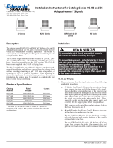
1. Select a mounting configuration (Figure 1).
Note: When mounting using the 105BM mounting bracket, the
105BX outlet box attachment must also be used as shown in
Figure 2.
2. Pull field wiring into the mounting attachment.
3. Install the mounting attachment as follows:
a. 105BX: Screw the outlet box attachment to the mounting
surface (Figure 2) using two screws (not supplied) suitable for
the surface. Attach the adhesive backed gasket to the top of
the 105BX mounting box, being careful to line up the holes in
the gasket with the mounting holes in the outlet box.
b. 105BM: Using the four supplied screws, secure the mounting
bracket to the 105BX outlet box attachment as shown in
Figure 2. Attach the adhesive backed gasket to the top of the
105BM mounting bracket, being careful to line up the holes in
the gasket with the mounting holes in the outlet box.
c. 105PM: Install 3/4 in. conduit. Screw the pipe mount
attachment onto the 3/4 in. conduit. Attach the adhesive
backed gasket to the top of the 105PM pipe mount attachment
(Figure 3), being careful to line up the holes in the gasket with
the mounting holes in the outlet box.
4. Attach the signal’s wire leads to the field wiring as shown in
Figure 5.
Note: It is not necessary to remove the lens from the high intensity
strobe base to install the 105DHIST Series strobes.
5. Secure the hi-intensity strobe base to the appropriate mounting
attachment using the four supplied screws as shown in Figure 3.
6. Apply power and verify operability.
Figure 1: Mounting configurations
Mounted on a 105PM pipe mount
attachment
Mounted on a 105BX outlet box
attachment
Mounted on a 105BM mounting
bracket with the 105BX outlet box
attachment

2 / 4 P/N 3100394-EN • REV 04 • ISS 14JAN15
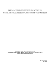
Figure 2: Mounting 105BM mounting bracket
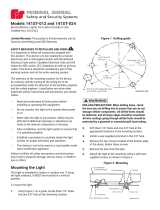
Figure 3: Securing the strobe to the 105PM pipe mount
attachment
Figure 4: Strobe tube replacement
Figure 5: Wiring diagram
Legend
(1) From power source or previous signaling device
(2) 105DHIST Series strobe
(3) EOLR
Wire nut
Notes
• Polarity is shown in the supervisory state (signal inactive). The
polarity reverses to activate the signal.
• Electrical supervision requires the wire run to be broken at each
device.
• This device uses a constant input voltage. Do not connect to a
“coded” or pulsating voltage.
• For non-fire alarm stand-alone use, tie the two red leads together
and tie the two black leads together.
105-L Series
lens
Countersunk screws
to mount lens to
105BM, supplied (4X)
Hi-intensity strobe
base
Mounting
surface
Screws to mount
105BX to the
mounting surface (2X)
Adhesive backed
gasket
Adhesive backed
gasket
105BM mounting
bracket
Screws to mount
105BM to 105BX,
supplied (4X)
Screws to mount
lens to 105PM,
supplied (4X)
105HI-L series lens
Hi-intensity strobe
base
Adhesive backed
gasket
105PM pipe mount
attachment
3/4 in. conduit nipple
Gasket
Beacon base
105-L Series lens
Strobe tube
Strobe tube base
Strobe tube
socket
(+)
RD
(+)
RD
BK BK
(+)
RD
(+)
RD
BK BK
(1)
(2) (3)(2)

P/N 3100394-EN • REV 04 • ISS 14JAN15 3 / 4
Maintenance
The lens should be cleaned periodically, using a mild detergent and
water on a soft, clean, lint-free cloth.
WARNING: To prevent electrical shock, before starting work on units,
disconnect power, and wait 5 minutes for stored energy to dissipate.
Caution: Do not touch the strobe tube with bare fingers. Grasp the
light source either by the base or using a soft, clean cloth.
To replace the strobe tube:
1. Unscrew the lens from the base.
2. Grasp the strobe tube by its base and pull straight up out of the
strobe tube socket (Figure 4).
3. Grasp the new strobe tube by the base and press into the strobe
tube socket.
4. Ensure that the clear gasket is on the base with the flared, open
end facing down. Screw the lens onto the base.
5. Apply power and verify operability.
Specifications
Voltage
20 to 30 VDC [1]
Current
See Table 2 [2]
Flash rate
65 flashes per minute (approximate)
Lamp energy
8 joules
Lamp ratings
300,000 peak cd
Lamp life
3,000 hours [3]
Dimensions
Refer to Table 3
[1]
Caution: To prevent damage to the strobe’s internal circuit and to
ensure that it continues
to function properly, do not operate the strobe
outside of the special application voltage range of 20 to 30 VDC.
[2]
Use the operating current to establish the wire gauge and standby
power requirements. Consult the control unit manufacturer to
determine s
urge and peak current effects and maximum number of
strobes on the system.
[3] Strobe tube life at operating power to 75% of initial light output.
Figure 6: Wall mount, dome horizontal, vertical and horizontal
viewing plane
Notes
Values are for the clear lens only
0° axis looking at end of dome
UL 1971 Hearing Impaired: 26 cd wall rating
UL 1638 General Utility: 26 cd at 0° axis
Figure 7: Wall mount, dome down, vertical viewing plane
Notes
Values are for the clear lens only
0° axis looking at side of dome
UL 1971 Hearing Impaired: 24 cd wall
UL 1638 General Utility: 94 cd at 0° axis
Figure 8: Ceiling mount viewing plane
Notes
Values are for the clear lens only
0° axis looking at end of dome
UL 1971 Hearing Impaired: 26 cd wall rating
UL 1638 General Utility: 26 cd at 0° axis
Table 1: Hazardous location ratings
Model
Class Division Group Operating
temperature
105DHIST*
-FJ I 2 A, B, C, D T2C (230˚C, 446˚F)
II 2 F, G T4 (135˚C, 275˚F)
III 1, 2 T4 (135˚C, 275˚F)
* Letter in this position indicates color of the lens: A = Amber, B = Blue,
C = Clear, G = Green, R = Red, or W = White

4 / 4 P/N 3100394-EN • REV 04 • ISS 14JAN15
Table 2: Voltage specifications
Operating current [1]
Initial surge inrush
current
Repetitive surge
current
Voltage [2]
RMS
current
Current
(A)
Time
(mS)
Current
(A)
Time
(mS)
20 VDC
1.08 2.28 1.10 1.64 450
24 VDC
0.95 2.60 1.13 1.52 400
28 VDC
0.85 2.80 1.24 1.48 381
30 VDC
0.83 2.92 1.7 1.44 360
[1]
Use the operating current to establish the wire gauge and standby
power requirements. Consult the control unit manufacturer to
determine surge and peak current effects and maximum number of
strobes on the system.
[2]
Caution: To prevent damage to the internal circuit, and to ensure
that it continues to function properly
, do not operate the unit outside of
the Special Application voltage range of 20 to 30 VDC.
Table 3: Dimensions
105DHIST
-FJ strobe
module
105PM pipe mount
attachment
105BX outlet box
attachment
105BM mounting
bracket (use with
105BX)
Table 4: Replacement parts
Catalog number
Description
92
-ST
Strobe tube
105
-LC
Lens (clear only)
Regulatory information
North American
standards
ANSI/ISA 12.12.01
CAN/ULC-S526
CSA C22.2 No. 157
CSA C22.2 No. 205
CSA C22.2 No. 213
UL 1638
UL 1971
CSFM Listed for special application 20 to 30 VDC
Contact information
For contact information, see www.edwardssignaling.com.
© 2015 UTC Fire & Security Americas Corporation, Inc.
All rights reserved.
3.625 in.
(92 mm)
4.75 in.
(121 mm)
3.75 in.
(95 mm)
4.5 in.
(114 mm)
2.25 in.
(57 mm)
4.5 in.
(114 mm)
2 in.
(51 mm)
5.25 in.
(133 mm)
6 in.
(152 mm)
Ø
11/32 in.
(0.7 mm)
5 in.
(127 mm)
4.5 in.
(114 mm)
/