
ProMinent
®
General Operating Instructions
ProMinent
®
Motor-Driven Metering Pumps
and Hydraulic Accessories
Hydro
Two sets of operating instructions are necessary to ensure safe operation of the metering pumps corresponding to their
intended purpose: The product-specific operating instructions (e.g. for Sigma) and the general operating instructions
for ProMinent
®
motor-driven metering pumps.
Both are only applicable in conjunction with each other.
Please completely read through these operating instructions first! Do not discard!
The warranty shall be invalidated by damage caused by operating errors!
Part No. 987702 ProMinent Dosiertechnik GmbH
• 69123 Heidelberg • Germany BA MOZ 013 07/03 GB
Meta
Makro TZ
Sigma
alpha
Vario
Makro/ 5

ProMinent
®
ProMinent
®
Page 2
Imprint
Imprint:
General Operating Instructions for
ProMinent
®
Motor-Driven Metering Pumps
© ProMinent Dosiertechnik GmbH, 1995
Address:
ProMinent Dosiertechnik GmbH
Im Schuhmachergewann 5-11
69123 Heidelberg
Germany
www.prominent.de
Subject to technical modifications.

ProMinent
®
ProMinent
®
Page 3
Table of Contents
Table of Contents
User Information ................................................................................................................................................................................... 4
1 Application of Motor-Driven Metering Pumps
............................................................................................... 5
2 Safety Notes
................................................................................................................................................................................... 5
2.1 Summary of additional safety instructions for the EX version of the pump
(in accordance with ATEX)
....................................................................................................................................... 6
2.1.1 Additional remarks for the application for metering inflammable media
........................... 7
2.1.2 Safety devices
................................................................................................................................................................... 7
2.1.3 EC conformity declaration / certificates
....................................................................................................... 7
3 Mounting ............................................................................................................................................................................................ 8
4 Installation, hydraulic
............................................................................................................................................................ 9
4.1 Standard Installation
.................................................................................................................................................... 10
4.2 Notes on Installation on Intake Side
............................................................................................................... 11
4.3 Notes on Installation on Delivery Side
........................................................................................................... 12
4.4 How not to install pumps
......................................................................................................................................... 14
4.5 Special Notes on Installation
................................................................................................................................. 15
5 Installation, electrical
............................................................................................................................................................ 17
5.1 Motor ........................................................................................................................................................................................ 17
5.2 Other electrical components in explosive zones )
............................................................................... 19
6 Start-Up .............................................................................................................................................................................................. 19
7 Maintenance
................................................................................................................................................................................... 20
8 Troubleshooting
.......................................................................................................................................................................... 21
9 Hydraulic Accessories
.......................................................................................................................................................... 22
9.1 Overview and Notes on Accessories
.............................................................................................................. 22
9.2 Pressure Control/Safety Overflow Valve
...................................................................................................... 24
9.3 Pulsation Dampers
........................................................................................................................................................ 25
Appendix ............................................................................................................................................................................................ 27
Warranty Application for Metering Pumps and Accessories
.................................................................... 27
Data for Calculating Metering Line ................................................................................................................................. 28
Installing Drawing
......................................................................................................................................................................... 29

ProMinent
®
ProMinent
®
Page 4
User Information
Please read through the following user guidelines. Familiarity with these points ensures optimum
use of the operating instructions.
Key points in the text are indicated as follows:
• Enumerated points,
S Hints
Working Guidelines:
NOTE
Notes on operation.
Safety Guidelines:
WARNING
There is a danger to life or the risk of serious injury if the notes on safety are disregarded!
CAUTION
There is a danger of slight injury and damage to property if the notes on safety are
disregarded!
IMPORTANT
There is a danger of damage to property if the notes on safety are disregarded.
These general operating instructions for motor-driven metering pumps and hydraulic assemblies
apply only in conjunction with the product-related pump operating instructions for e.g. alpha,
Vario, Meta, Sigma, Hydro, Makro/ 5 and Makro TZ motor-driven metering pumps.
User Information

ProMinent
®
ProMinent
®
Page 5
Application of Motor-Driven Metering Pumps / Safety Notes
1 Application of Motor-Driven Metering Pumps
ProMinent
®
motor-driven metering pumps and accessories are to be used solely for the purpose
of metering liquid media!
In explosion-threatened workplaces in zone 1, device category II 2G of explosion group II C the
pump may not be operated without the corresponding rating plate (and the corresponding EC
conformity declaration) for pumps for explosion-threatened workplaces in accordance with
guideline 94/9/EC of the European guidelines. The explosion group, category and type of
protection shown on the marking must correspond to or exceed the conditions prevailing in the
intended area of application.
All other uses or modifications are prohibited!
Pumps may never be operated in explosion-threatened workplaces without a corresponding
rating plate (and the corresponding EC conformity declaration) for pumps for explosion-
threatened workplaces.
ProMinent
®
motor-driven metering pumps and accessories are not to be used for the purpose of
metering gasses and solids!
Refer to the relevant product-related operating instructions and product cataloque for the
technical data of the type of motor-driven metering pump used!
Decisive criteria relating to the intended use of the pumps are
• EX-protection of the pump
• Resistance of parts coming in contact with metered medium
• Pressure and temperature of metered medium
2 Safety Notes
WARNING
• Immediately switch off the pump in case of emergency! Use the power switch on
the pump or an emergency switch in your immediate operating environment!
• Pumps for radioactive medium must not be shipped through standard channels!
• If using the metering pump for metering flammable media for Europe e.g. the European
operator’s guideline 99/92/EC* (ATEX 137**), (in Germany implemented via the new
operating safety ordinance (Official Federal Gazette for 2002, Part 1, No. 70, issued
in Bonn 2.10.2002) and the German dangerous chemicals ordinance))!
* previously Ex Vo, Vb F
** previously ATEX118A
• Observe applicable national regulations for installation abroad!
CAUTION
• Do not obstruct or block access areas!
Pumps must be accessible at all times to facilitate operation and maintenance.
• Only specially trained and authorized persons are permitted to carry out maintenance
and repairs on metering pumps and their periphery!
• Always depressurize the liquid end first before carrying out any work on the pump!
• If hazardous or unknown metering media are used, discharge and flush the liquid end
before carrying out any work on the pump!
• Observe safety specifications for liquid metered media! Corresponding protection and
emergency measures must be implemented prior to initial operation.
• Always wear protective clothing (safety goggles, gloves,...) when handling hazardous or
unknown liquid media! This applies particularly when working on the liquid end!
• Do not use parts which have not been tested and approved by ProMinent for assembly of
ProMinent
®
motor-driven metering pumps since this can result in damage to persons and
property, for which no liability will be accepted!
• Install safety devices in the system, e.g. overflow valves!
ProMinent
®
motor-driven pumps are oscillating displacement pumps. Irrespective of
whether the delivery line is closed, e.g. by closing off the delivery line or by closing a valve,
the pressure produced by the pump can reach a multiple of the permissible working
pressure of the system or of the metering pump. This can result in lines bursting with
dangerous consequences particularly in the presence of aggressive or toxic media!
• Piston pumps are always equipped with a dry-run protection facility to avoid the pump

ProMinent
®
ProMinent
®
Page 6
Safety Notes
packing running dry as this may cause overheating and thus premature wear.
IMPORTANT
• Based on state-of-the-art technology, the manufacturer carefully selects the materials
for parts coming into contact with the medium as specified by the customer.
The manufacturer shall not be liable for any damage caused by metering other media
or media which has been modified with regard to its properties (concentration, density,
temperature, additives, impurities etc.).
• Avoid over-feed with positive pressure difference (at least 1 bar) between discharge
and suction sides.
• Only specially instructed personnel are permitted to operate the metering pump.
The operator must ensure by applying appropriate accident prevention measures that
operating personnel are not endangered under given operating conditions (pressure,
temperature, aggressivity etc.).
2.1 Summary of additional safety instructions for the EX version of the pump
(in accordance with ATEX)
WARNING
• In explosion-threatened workplaces in zone 1, device category II 2G of explosion
group II C the pump may not be operated without the corresponding rating plate (and
the corresponding EC conformity declaration) for pumps for explosion-threatened
workplaces in accordance with guideline 94/9/EC of the European guidelines.
• All other uses or modifications are prohibited!
• Pumps may never be operated in explosion-threatened workplaces without a corres-
ponding rating plate (and the corresponding EC conformity declaration) for pumps for
explosion-threatened workplaces.
• Installations in potentially explosive atmospheres must be inspected by a „accredited
qualified“ person. This applies in particular also for intrinsically safe electrical circuits.
• Observe all relevant standards e.g. DIN EN 60079, DIN EN 50020, DIN VDE 0165 and/
or DIN VDE 0118 “Installing electrical equipment in explosion-threatened areas”!
• When installing the metering pump, observe the directives for the installation of
devices in explosion-threatened areas, e.g. for Europe the European operator’s
guideline 99/92/EC (ATEX137)*, (in Germany implemented via the new operating safety
ordinance (Official Federal Gazette for 2002, Part 1, No. 70, issued in Bonn 2.10.2002))!
* previously ElexV
• Read the documentation provided for the individual electrical components.
• On principle, metering pumps in potentially explosive atmospheres must be equipped
with a safety overflow valve at the outlet side of the pump (serves as protection against
overheating due to overload and against sparks produced by shock due to overload
which has led to the breakage drive parts.)
• Piston metering pumps, used in temperature class T4, must be equipped with a flow
control at the outlet side (serves as protection against excess temperature due to dry-
running.)
• For metering pumps with hydraulically actuated diaphragm, the pump must also be
provided with a flow control, if used in temperature class T4. (Protection against
improper heating in case of permanent operation via the internal overflow valve.)
• Drive motors must be secured by an appropriate motor protection switch. A motor
protection approved for this application must be used for Ex”e”-motors. (Protection
against heating due to overload)
• Observe also all relevant standards e.g. DIN EN 60079-10/14 and DIN EN 50020
for installations in explosion-threatened areas!
• Note all national directives which apply to the installation!
• The proper general function, in particular of the drive, must be safeguarded by regular
inspections (leakages, noises, temperatures, possible discoloration due to excess
temperatures....).
• Use original spare parts should exchange become necessary!

ProMinent
®
ProMinent
®
Page 7
Safety Notes
• Wear parts (diaphragms, bearings etc.) of metering pumps used in potentially explosive
atmospheres must be replaced after having completed 90% of their nominal product
life.
• The lubricant supply must be regularly checked for lubricated pumps, for instance by
checking the fill level, visual inspection for leakages etc.
The pump must never be allowed to overheat due to lack of oil!
• Examine the pump for oil leaks and remedy the cause!
The pump must never be allowed to overheat due to lack of oil!
• Check that the pressure relief valve downstream from the pump is functioning
correctly!
The pressure relief valve must prevent the gearbox from being overloaded and
overheating in explosion-threatened workplaces!
• When cleaning plastic parts, attention must be paid to not generating any electrostatic
charge by rubbing excessively. - see danger sign.
• These measures are the minimum protection measures specified by ProMinent.
Should the user know about any further risks, it is his duty to eliminate them by taking
corresponding measures.
2.1.1 Additional remarks for the application for metering inflammable media
• Inflammable media may only be lifted with stainless steel liquid ends. - For exceptional
cases, where this is not possible, also PTFE with carbon may be used, our versions TT_ are
made of conductive plastics. In this case, special attention must be paid by the user due to
the lower mechanical stability.
• Piston metering pumps must not be used for inflammable media. - Suitable additional
control measures must be taken for safeguarding the necessary safety where the application
of piston pumps cannot be avoided: flow control + control of leaking pistons, as well as an
additional temperature control at the liquid end in case of media used having critical frictional
behaviour.
• Hydraulic diaphragm pumps are well suited, however, version with diaphragm rupture
monitor Ex”i” and a flow control is obligatory.
• Diaphragm pumps with mechanically actuated diaphragm, at present MTMa.., TZMa..,
Sigma’s S1Ba...., S2BaHM..., S3Ba: no additional measures necessary, however, version with
diaphragm rupture indicator, version Ex”i”*, must be used on principle.
• For all metering pumps for metering inflammable media applies: starting up and emptying
only supervised by a competent person.
WARNING
• If using the metering pump for metering flammable media for Europe e.g. the European
operator’s guideline 99/92/EC* (ATEX 137**), (in Germany implemented via the new
operating safety ordinance (Official Federal Gazette for 2002, Part 1, No. 70, issued in
Bonn 2.10.2002) and the German dangerous chemicals ordinance))!
* previously Ex Vo, Vb F
** previously ATEX118A
• When installing the metering pump, observe the directives for the installation of
devices in explosion-threatened areas, e.g. for Europe the European operator’s guide-
line 99/92/EC (ATEX 137)*, (in Germany implemented via the new operating safety
ordinance (Official Federal Gazette for 2002, Part 1, No. 70, issued in Bonn 2.10.2002))!
* previously ElexV
2.1.2 Safety devices
The following safety notice must be
affixed to the the pump
(PP, PC and PV liquid ends, acrylic glass cover, ...)
2.1.3 EC conformity declaration / certificates
The EC conformity declaration for pumps for explosion-threatened workplaces is supplied with
the pump (the copy of the EC conformity declaration for the pump itself does not apply to
pumps designed for explosion-threatened workplaces).
The EC conformity declarations, the EC series prototype test reports and the operating manuals
for the individual components are also supplied with the pump.

ProMinent
®
ProMinent
®
Page 8
3 Mounting
IMPORTANT
• Mount the metering pump upright with the feet on a horizontal base. Refer to the
corresponding data sheets for the dimensions (m) of the securing holes.
DNm
m
fig..1
• The frame or the foundation for mounting the pump must be designed such as to
ensure the unit is free of vibration and stable.
fig. 2
• Install pump at convenient operating level and mount such that the valves are vertical:
head valve always at top and intake valve always at bottom.
fig. 3
Head valve
Intake valve
Liquid end
f
f
f
• Ensure adequate clearance (f) in area of liquid end as well as intake valve and head
valve so that these parts can be easily removed if required.
fig. 4
A
A
• Set up the pump such that the stroke length adjustment, indicator scale A, oil level
indicator, oil filler and drain plugs as well as the valves are easily accessible for
servicing.
fig. 5
DN pipe
DN
pump valve
DN pump valve
•
Ensure nominal diameters of pipes and installed fittings are the same size or larger
than the nominal diameters of the pump valves (intake and head valves).
Mounting

ProMinent
®
ProMinent
®
Page 9
4 Installation, hydraulic
WARNING
• EX-pump only: when installing the metering pump, observe the directives for the
installation of devices in explosion-threatened areas, e.g. for Europe the European
operator’s guideline 99/92/EC (ATEX 137)*, (in Germany implemented via the new
operating safety ordinance (Official Federal Gazette for 2002, Part 1, No. 70,
issued in Bonn 2.10.2002))!
* previously ElexV
• EX-pump only:
also observe relevant standards e.g. DIN EN 60079-10/14 and DIN EN 50020 for
installations in explosion-threatened areas!
• Note all national directives which apply to the installation!
IMPORTANT
• In order to check pressure conditions in the piping system, it is recommended to
provide connection facilities for pressure gauges in the vicinity of the intake and
delivery connection piece.
• Connect pipes to the pump such that there is no stress or strain whatsoever acting
on the pump, such as offset, weight or expansion of the pipe. Only use a flexible pipe
adapter for connecting steel/stainless steel pipes to plastic pump housings.
fig. 6
Pressure
gauge sleeve
Pipe
(delivery line)
Pressure
control valve
Intake valve
Pipe
(intake line)
Pressure
gauge sleeve
Installation, hydraulic
fig. 7
Steel/stainless steel
pipe
Flexible pipe adapter
Plastic connecting piece

ProMinent
®
ProMinent
®
Page 10
Installation, hydraulic
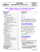
4.1 Standard Installation
Delivery line
Metering tank
Diagram 8
Metering pump Dirt trap
Metering valve Solenoid valve
Adjustable pressure control valve
PD
Pulsation damper
(Overflow valve)
Foot valve with sieve filter Float valve
Pressure gauge Filler device
Ball check valve Siphon vessel
Shut-off cock valve

ProMinent
®
ProMinent
®
Page 11
4.2 Notes on Installation on Intake Side
NOTE
Avoid the intake line running empty:
h
fig. 9
• Install foot valve at end of intake line when the pump is higher than the max. liquid level
in the intake tank.
• The calculated size h (see diagram) must not be greater than the specified pump
suction head divided by the density of the delivered medium.
• Use short intake line and avoid thin-walled hoses.
NOTE
Connect intake line to tank slightly above the base of the tank.
IMPORTANT
Provide suitable means for retaining impurities!
Otherwise they can cause faults in the pump and system!
E.g. install a dirt trap (mesh size 100–400 µm depending on medium and type of metering
pump).
NOTE
fig. 11
Install pump with inlet on intake side for gas-emitting media.
NOTE
Intake via siphon line for high-level tanks without connection facilities at base of tank:
fig. 12
• Install filler facility for siphon line (intake line).
• Observe acceleration pressures due to the longer intake line.
Installation, hydraulic
fig. 10

ProMinent
®
ProMinent
®
Page 12
fig. 15
Installation, hydraulic
4.3 Notes on Installation on Delivery Side
WARNING
EX-pump only:
• On principle, metering pumps in potentially explosive atmospheres must be equipped
with a safety overflow valve at the outlet side of the pump (serves as protection against
overheating due to overload and against sparks produced by shock due to overload
which has led to the breakage drive parts.)
• Piston metering pumps, used in temperature class T4, must be equipped with a flow
control at the outlet side (serves as protection against excess temperature due to dry-
running.)
• For metering pumps with hydraulically actuated diaphragm, the pump must also be
provided with a flow control, if used in temperature class T4. (Protection against
improper heating in case of permanent operation via the internal overflow valve.)
IMPORTANT
Do not exceed permissible nominal pressure! Otherwise the pump may be damaged!
fig. 13
Provide an overpressure facility if the permissible pressure in the pump head can be
exceeded, e.g. by closing a shut-off element or a blockage in the line:
• Install overflow valve in the delivery line or
• use an overflow valve integrated in the pump housing (depending on type, refer to
data sheet of the type of pump used).
The following points must be observed with regard to the overflow line when using an
overflow valve:
• Route the overflow line with a drop into the supply tank under atmospheric pressure
or into an open runoff channel.
• Connect the overflow line to the intake line, however, only if there is no check valve in
the intake line.
IMPORTANT
Do not use a non-return check valve on the intake side for the overflow return as it may
cause the intake line to tear off.
fig. 14
IMPORTANT
Cut off the return flow from the main line!
Otherwise unwanted mixing in the metering line can occur.
• Install the metering valve at the injection point.

ProMinent
®
ProMinent
®
Page 13
Installation, hydraulic
IMPORTANT
Dampen pulsation by installing pulsation dampers if
• low-pulsation delivery flow is required for process reasons;
• acceleration forces have to be reduced due to the geometry of the piping system.
The following can occur if acceleration forces are not dampened
• Fluctuations in delivery, metering faults, pressure surges, valve knocking and wear
as result of cavitation on the intake and delivery side of the pump.
• Mechanical destruction of pump, leakages and knocking of valves as result of the
permissible maximum pressure being exceeded on the pump delivery side.
fig. 16
*
PD
Pulsation damper in delivery line
(refer to section 5.3)
fig. 17
*
PD
Pulsation damper for free outlet:
• Install pressure control valve or metering valve at end of metering line.
Pusation damper without trails
(e.g. together with nozzles):
fig. 18
*
PD
• Interlock the solenoid valve electrically with the voltage supply of the metering pump.
* Accumulators without diaphragm:fit a vent valve

ProMinent
®
ProMinent
®
Page 14
Installation, hydraulic
4.4 How not to install pumps
IMPORTANT
Intake line cannot be bled
fig. 19
• Air pocket in intake line.
Pulsation damper not effective
fig. 20
PD
2
1
• Arrangement of pulsation damper (2) and pressure retension valve (1) incorrect.
fig. 21
Siphon effect
fig. 22
Admission pressure on intake side too high

ProMinent
®
ProMinent
®
Page 15
4.5 Special Notes on Installation
IMPORTANT
Avoid overloading by positive pressure difference between delivery side and intake side:
fig. 23
• Install end of delivery line higher than the liquid level in the intake tank.
or:
fig. 24
• Install outlet in pump delivery line which must be higher than the liquid level in the
intake tank.
or:
fig. 25
• Install pressure control valves in the pump delivery line.
IMPORTANT
Ensure constant pressure in the intake line!
Irregular pump flow can occur if the pressure from the take-off line or the intake tank
istransmitted.
fig. 26
• Ensure constant supply height when pump intake is from pressurized lines!
fig. 27
• Ensure constant supply level if intake is from high supply level!
Installation, hydraulic

ProMinent
®
ProMinent
®
Page 16
fig. 28
• Avoid siphon (suction) effect when metering into a main line under vacuum:
Install pressure control valve (DHV-SR) or metering valve in the metering line!
NOTE
When metering suspensions it is necessary to flush the pump head in order to avoid
deposits forming
• as intermittent flushing or
• flushing after switching off the pump.
IMPORTANT
Switch off metering pump before flushing!
Maximum permissible flushing pressure: 2 bar
Manual flushing device
Automatic flushing device
Flushing water
Flushing device
fig. 29
Flushing water
Timer
autom. flushing device
fig. 30
Installation, hydraulic

ProMinent
®
ProMinent
®
Page 17
Installation, electrical
5 Installation, electrical
WARNING
• EX-pump only: Installations in potentially explosive atmospheres must be inspected by
a „accredited qualified“ person. This applies in particular also for intrinsically safe
electrical circuits.
• EX-pump only: observe all relevant standards e.g. DIN EN 60079, DIN EN 50020 DIN
VDE 0165 and/or DIN VDE 0118 “Installing electrical equipment in explosion-threatened
areas”!
• EX-pump only: when installing the metering pump, observe the directives for the
installation of devices in explosion-threatened areas, e.g. for Europe the European
operator’s guideline 99/92/EC (ATEX 137)*, (in Germany implemented via the new
operating safety ordinance (Official Federal Gazette for 2002, Part 1, No. 70, issued
in Bonn 2.10.2002))!
* previously ElexV
• EX-pump only: Read the documents provided for the individual electric components!
5.1 Motor
IMPORTANT
• Connect electric motor in accordance with VDE regulations as illustrated in the circuit
diagram provided.
• Check that the mains voltage and frequency agree with the values specified on the
motor ratings plate.
• Provide corresponding motor protection devices in order to protect the motor from
overload (e.g. motor protection switch with thermal overcurrent release).
Fuses are not motor protection devices!
• Drive motors must be secured by an appropriate motor protection switch. A motor
protection approved for this application must be used for Ex”e”-motors. (Protection
against heating due to overload)
• The specified rated motor output applies at a maximum ambient temperature of 40 °C
and installation altitudes below 1000 m above sea level.
The motor output will be reduced if these values are exceeded (refer to VDE 0530).
• Ensure unobstructed supply of cooling air!
• Installation in wet rooms or in the open:
S Arrange terminal box such that the cable lead-ins point downwards the bottom (can be taken
into account when ordering).
S Select PG screw glands suitable for the supply line, use reducer if necessary.
Seal cable lead-in well otherwise all other measures will be of little use.
S Apply sealing compound to PG screw glands and thread of dummy plugs, firmly tighten and
coat once again with sealing compound.
S Thoroughly clean sealing surfaces of terminal box and terminal box cover before re-installing.
Seals must be bonded on one side.
After a longer operating period, replace brittle seals by new ones.
Different types of motors are used depending on the application and required output.
ProMinent will send you the motor data sheets for the desired motor versions on request.
Motors for explosion-threatened workplaces
WARNING
• Motors in EX-areas must be installed and checked by persons with „recognised skills!
• Observe the operating manual supplied with the EX motor!

ProMinent
®
ProMinent
®
Page 18
Motors connected to three-phase AC network
Three-phase squirrel-cage motor
- circuit
circuit
-
L1 L2 L3
L1
L2 L3
W1
U2 V2
V1U1
W2
W1V1U1
U2 V2W2
Low voltage
High voltage
fig. 31
Example:
Specified rating 230/400 V
Three-phase network available 400 V
Correct motor connection Y-circuit
Direction of rotation reversal: Interchange 2 supply lines
Pole-changing three-phase AC motor (2 speeds in Dahlander circuit)
When changing over speed with pole selector switch, the star bridge 1U-1V-1W is realized
externally (in switch).
L1 L2 L3
W1
V2 W2
V1U1
U2
L1 L2 L3
W1V1U1
V2 W2U2
Low speed
High speed
fig. 32
Motors connected to alternating current network
Any three-phase AC motor can be operated in conjunction with a corresponding running
capacitor on the alternating current network. However, care must be taken to ensure that the
starting torque is only approx. 30 % of the rated torque.
Three-phase AC motor with running capacitor (Steinmetz circuit)
L1 N
CB
W1
V2 W2
V1U1
U2
fig. 33
Motors with electronic speed adjustment
Refer to the circuit diagram of the control system for connection of the motor if electric motors
are driven by electronic control devices, e.g. three-phase AC motors by frequency converters or
DC motors by thyristor controllers.
Installation, electrical

ProMinent
®
ProMinent
®
Page 19
Installation, electrical / Start-Up
External fans
IMPORTANT
For motors with separate cooling fan (identification code feature „R“ or „Z“), a separate
power supply is used for the separate cooling fan!
Actuators/servomotors for stroke length adjustment
Electrical connection of the motors is shown on the enclosed terminal connection diagram and
on the connection diagram provided on the inside of the housing.
IMPORTANT
Stroke length adjustment/control drives must only be operated with the pump running!
5.2 Other electrical components in explosive zones
WARNING
• Installations in potentially explosive atmospheres must be inspected by a „accredited
qualified“ person. This applies in particular also for intrinsically safe electrical circuits.
• Read the documentation provided for the individual electrical components.
6 Start-Up
WARNING
• When using with flammable media:
Additional remarks for the application for metering inflammable media.
- Inflammable media may only be lifted with stainless steel liquid ends. For exceptional
cases, where this is not possible, also PTFE with carbon may be used, our versions
TT are made of conductive plastics. In this case, special attention must be paid by the
user due to the lower mechanical stability.
- Piston metering pumps must not be used for inflammable media. Suitable additional
control measures must be taken for safeguarding the necessary safety where the
application of piston pumps cannot be avoided: flow control + control of leaking
pistons, as well as an additional temperature control at the liquid end in case of
media used having critical frictional behaviour.
- Hydraulic diaphragm pumps are well suited, however, version with diaphragm rupture
monitor Ex”i” and a flow control is obligatory.
- Diaphragm pumps with mechanically actuated diaphragm, at present MTMa.., TZMa..,
Sigma’s S1Ba...., S2BaHM..., S3Ba: no additional measures necessary, however,
version with diaphragm rupture indicator, version Ex”i”*, must be used on principle.
- For all metering pumps for metering inflammable media applies: starting up and
emptying only supervised by a competent person.
• If using the metering pump for metering flammable media for Europe e.g. the European
operator’s guideline 99/92/EC* (ATEX 137**), (in Germany implemented via the new
operating safety ordinance (Official Federal Gazette for 2002, Part 1, No. 70, issued in
Bonn 2.10.2002) and the German dangerous chemicals ordinance))!
* previously Ex Vo, Vb F
** previously ATEX118a
• On principle, metering pumps in potentially explosive atmospheres must be equipped
with a safety overflow valve at the outlet side of the pump (serves as protection against
overheating due to overload and against sparks produced by shock due to overload
which has led to the breakage drive parts.)
• Piston metering pumps, used in temperature class T4, must be equipped with a flow control
at the outlet side (serves as protection against excess temperature due to dry-running.)
• For metering pumps with hydraulically actuated diaphragm, the pump must also be
provided with a flow control, if used in temperature class T4. (Protection against
improper heating in case of permanent operation via the internal overflow valve.)
• EX-pump only: when installing the metering pump, observe the directives for the
installation of devices in explosion-threatened areas, e.g. for Europe the European
operator’s guideline 99/92/EC (ATEX 137)*, (in Germany implemented via the new
operating safety ordinance (Official Federal Gazette for 2002, Part 1, No. 70, issued
in Bonn 2.10.2002))!
* previously ElexV

ProMinent
®
ProMinent
®
Page 20
Start-Up / Maintenance
• EX-pump only: also observe relevant standards e.g. DIN EN 60079-10/14 and
DIN EN 50020 for installations in explosion-threatened areas!
• Note all national directives which apply to the installation!
IMPORTANT
• Based on state-of-the-art technology, the manufacturer carefully selects the materials
for parts coming in contact with the medium as specified by the customer.
The manufacturer shall not be liable for any damage caused by metering other media
or media which has been modified with regard to its properties (concentration, density,
temperature, additives, impurities etc.).
• Only specially instructed personnel are permitted to operate the metering pump.
The operator must ensure by applying appropriate accident prevention measures that
operating personnel are not endangered under given operating conditions (pressure,
temperature, aggressivity etc.).
IMPORTANT
• Refer to the information provided in the product-specific operating instructions.
• Before starting up, check correct connection of the drive motor as well as the
corresponding additional equipment!
• Check intake and delivery lines for leaks!
• Check whether necessary flushing lines are connected!
• Provide suitable type of safety overflow valves in all delivery lines!
S Bleed delivery side:
Switch on pump and run at 100 % stroke length until liquid end is full.
Switch off pump.
S Close bleeder on delivery side.
Pump is now ready for operation.
S Open shut-off valve in metering line, operate pump.
S Check cut-in pressure of overflow valve.
S Check delivery capacity and correct if necessary.
IMPORTANT
• If a compressed air vessel is installed on the delivery side, vent at regular intervals!
• Ensure the correct gas admission pressure (approx. 60–80 % of the mean operating
pressure).
• Observe the information provided in the operating instructions of the frequency
converter if using pumps with speed control.
7 Maintenance
WARNING
• The proper general function, in particular of the drive, must be safeguarded by regular
inspections (leakages, noises, temperatures, possible discoloration due to excess
temperatures....).
• Use original spare parts should exchange become necessary!
• Wear parts (diaphragms, bearings etc.) of metering pumps used in potentially explosive
atmospheres must be replaced after having completed 90 % of their nominal product
life.
• The lubricant supply must be regularly checked for lubricated pumps, for instance by
checking the fill level, visual inspection for leakages etc.
The pump must never be allowed to overheat due to lack of oil!
• Examine the pump for any oil leaking out and remedy the cause!
The pump must never be allowed to overheat due to lack of oil!
• Check that the pressure relief valve downstream from the pump is functioning correctly!
The pressure relief valve must prevent the gearbox from being overloaded and
overheating in explosion-threatened workplaces!
• EX-Pump only: When cleaning plastic parts, attention must be paid to not generating
any electrostatic charge by rubbing excessively. - see danger sign.
Page is loading ...
Page is loading ...
Page is loading ...
Page is loading ...
Page is loading ...
Page is loading ...
Page is loading ...
Page is loading ...
Page is loading ...
-
 1
1
-
 2
2
-
 3
3
-
 4
4
-
 5
5
-
 6
6
-
 7
7
-
 8
8
-
 9
9
-
 10
10
-
 11
11
-
 12
12
-
 13
13
-
 14
14
-
 15
15
-
 16
16
-
 17
17
-
 18
18
-
 19
19
-
 20
20
-
 21
21
-
 22
22
-
 23
23
-
 24
24
-
 25
25
-
 26
26
-
 27
27
-
 28
28
-
 29
29


ProMinent Makro 5 Series General Operating Instructions
- Type
- General Operating Instructions
Ask a question and I''ll find the answer in the document
Finding information in a document is now easier with AI
Related papers
-
Sigma S2Ca Operating instructions
-
ProMinent S2Ca User manual
-
-
-
ProMinent Makro TZKa Operating Instructions Manual
-
-
-
-
-
Other documents
-
BE MC16 Owner's manual
-
Grundfos CSD Installation And Operating Instructions Manual
-
LMI SG76P8P Owner's manual
-
Dover PSG NEPTUNE 637 Operation & Maintenance Manual
-
DAB E.SYBOX MINI 3 User manual
-
Pulsafeeder Pulsa 7120 Owner's manual
-
TapFlo TX25 Original Instruction
-
DAB ESYBOX MINI 3 User manual
-
 American Aldes DHV-150H User manual
-
Shafer Hand Pump Double Holding Valve Owner's manual
