Star Trac E Series Upright E-UBi Gen. 1 Installation guide

Type
Installation guide
Star Trac
®
Fitness
E Series Bikes
E- UB 8100/ E- RB 8110
Install Guide
Step 2a
STAR TRAC E SERIES BIKES
Install Guide
ASSEMBLY AND SETUP E-UB
UNPACKING
NOTE: Do not remove the base from the shipping carton at this time.
Remove the top cover from the shipping carton. Remove all parts and shipping supports (except the base) from the carton, and
verify that the following parts are included in your shipment:
Description Qty
Base 1
Display Weldment 1
Neck Tube 1
Seat Tube with Seat and Sleeve 1
Bolt, Allen Head, M8 x 16 mm 4
Description Qty
Washer, M8 4
Bolt, Allen Head, M6 x 65 4
Star Washer, M6 4
Bolt, Allen Head M4 x 20 2
Bolt, M6 x 10 1
This owner’s manual and the warranty card are also included in the packaging.
Note: This manual covers installation of the LED display. If you ordered a PVS kit or an
Embedded Display, please refer to the assembly and operating instructions included with those
products for proper setup and operation of the display assembly.
TOOLS REQUIRED
Your STAR TRAC E- UB can be assembled using the following tools:
Metric Hex Key Wrenches
Metric Open-End Wrenches
Metric Ratchet Socket Wrench Set
Torque Wrench
Phillips Head Screwdriver
ASSEMBLY
1. Unpack and Position the Base
Cut the long edge of the shipping carton base at both ends. Fold the
flap down to make a ramp.
With the aid of a helper, lift the rear end of the base, and roll the base
off of the shipping carton platform. Place the base on the floor in the
location where the unit will be used. Be sure the chosen location is
level.
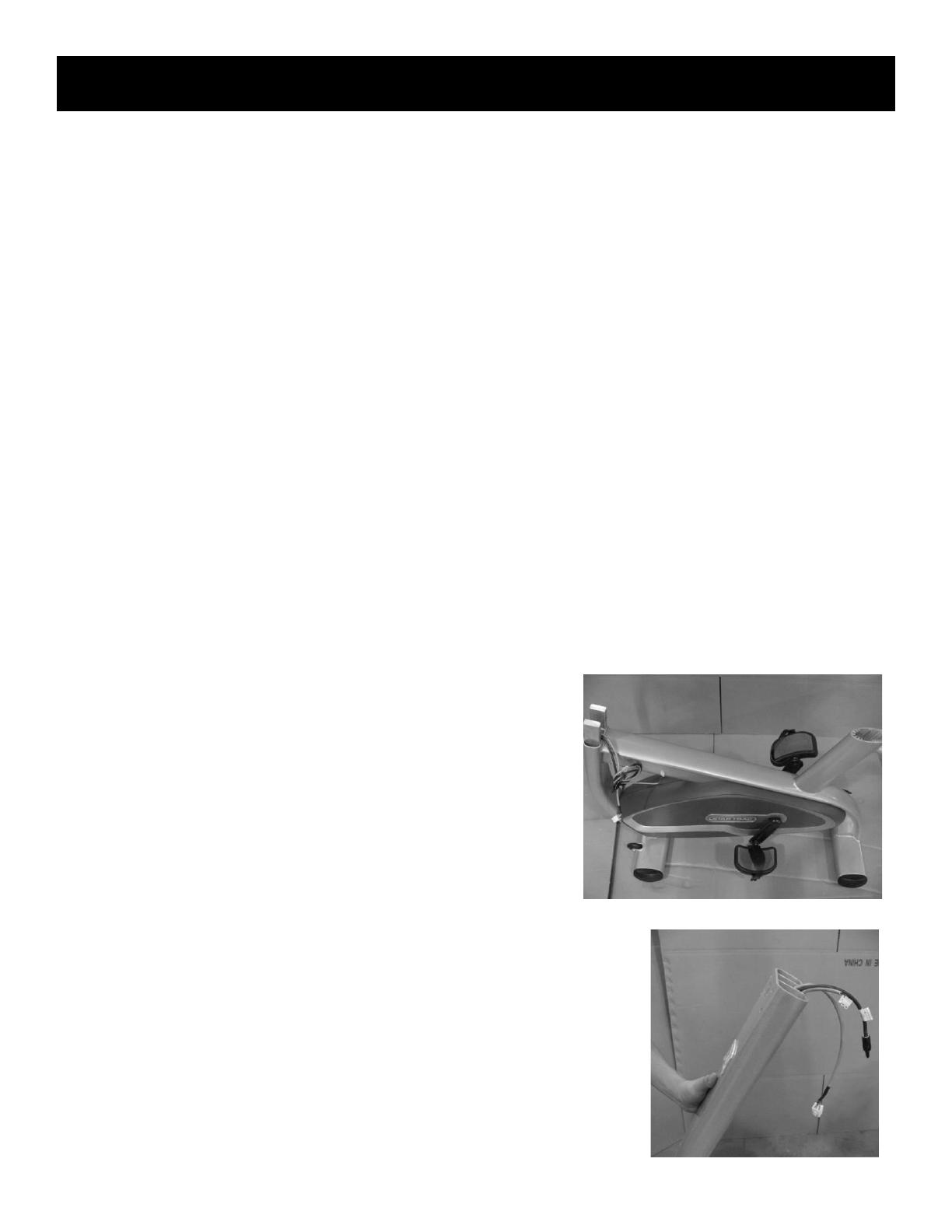
2. Install the Neck Tube and Display Weldment
NOTE: You will need someone to assist you to install the display weldment. Have
the person who is assisting you hold the display weldment while you route the
display cables and connect the neck.
Have your helper hold the neck tube close to the base, route the main I/O cable,
auxiliary power and coaxial cable up the full length of the display neck before
seating the neck on the base. See Figure 2a. Secure the neck tube with 4 M8
allen head bolts and washers and torque of 9-11 lbs-ft.
Step 1
SSTAR TRAC E SERIES BIKES
Install Guide
Next, position the display weldment on the top of the neck tube and secure with
the four M6 x 65 allen head bolts and four star washers. Take care to route the
display cables through the opening in the display weldment. All cables should
exit out the top of the neck tube as shown in the image below. Tighten the four
bolts to a torque of 8-10 lbs-ft.
3. Install the Seat Post
While pulling the release knob out, slide the seat post into the frame until the
threaded hole in the seat post is accessible through the external hole in the frame.
Install the M6 x 10 bolt through the opening in the frame and into the back of the
seat post and tighten to a torque of 8-10 lbs-ft.
Secure the seat post sleeve to the frame with two M4 x 20 allen head bolts.
Check the seat post for proper operation by pulling on the seat post release knob and
verifying that the seat post will slide up and down the full travel without difficulty.
NOTE: THIS COMPLETES THE ASSEMBLY OF THE BASE FRAME, TO COMPLETE
ASSEMBLY OF LED DISPLAY CONTINUE TO PAGE 15
Step 3a
Step 2b
Step 3b
STAR TRAC E SERIES BIKES
Install Guide
ASSEMBLY AND SETUP E-RB
UNPACKING
NOTE: Do not remove the base from the shipping carton at this time.
Remove the top cover from the shipping carton. Remove all parts and shipping supports (except the base) from the carton, and
verify that the following parts are included in your shipment:
Description Qty
Base 1
Display Weldment 1
Neck Tube 1
Seat Assembly 1
Bolt, Allen Head, M8 x 16 mm 4
Handlebar Assembly 1
Description Qty
Washer, M8 4
Bolt, Allen Head, M6 x 65 4
Star Washer, M6 4
Bolt, Allen Head M10 x 10 4
Washer, M10 4
This owners manual and the warranty card are also included in the packaging.
Note: This manual cover installation of the LED display. If you ordered a PVS kit or an
Embedded Display, please refer to the assembly and operating instructions included with those
products for proper setup and operation of the display assembly.
TOOLS REQUIRED
Your STAR TRAC E- RB can be assembled using the following tools:
Metric Hex Key Wrenches
Metric Open-End Wrenches
Metric Ratchet Socket Wrench Set
Torque Wrench
Phillips Head Screwdriver
ASSEMBLY
1. Unpack and Position the Base
Cut the long edge of the shipping carton base at both ends.
Fold the flap down to make a ramp.
With the aid of a helper, lift the rear end of the base, and
roll the base off of the shipping carton platform. Place the
base on the floor in the location where the unit will be
used. Be sure the chosen location is level.
Step 1
SSTAR TRAC E SERIES BIKES
Install Guide
2. Install the Display Weldment
NOTE: You will need someone to assist you to install the display weldment.
Have the person who is assisting you hold the display weldment while you
route the display cables and connect the neck.
Have your helper hold the neck tube close to the base, route the main I/O
cable, auxiliary power and coaxial cable up the full length of the display
neck then make sure the contact heart rate cable is clear before seating
the neck on the base. The See Figure 2a. Secure the neck tube with 4 M8
allen head bolts and washers and torque of 8-10 lbs-ft.
3. Install Adjustable Heart Rate Bar
Locate the adjustable heart rate bar.
Connect the cable from the hole in the neck
tube to the cable from the adjustable heart
rate bar.
Taking care to not pinch the cable assemble, mount the
adjustable heart rate bar to the neck tube with four M6 x 25 mm
allen bolts and four star washer. Tighten all four bolts to a
torque of 8-10 lbs-ft.
Check the adjustable heart rate bar for proper operation by
pressing the red button and sliding the heart rate bar back and
forth to verify normal operation without difficulty.
Step 2a
Step 3a
Step 2
Step 3b
STAR TRAC E SERIES BIKES
Install Guide
4. Install the Seat Assembly
.
Carefully position the seat frame over the seat
carriage on the bike frame, aligning the
attachment holes in the sides of the seat
frame with the holes in the seat carriage.
Using four M10 X 10 socket head screws and
four washers, secure the seat frame to the
seat carriage. Tighten all four screws securely
to a torque of 18-20 lbs-ft.
Verify operation by lifting up the red lever
and sliding the seat carriage from the front to
the back. Verify the latch engages when the
lever is released.
Step 4
  • Page 1 1
  • Page 2 2
  • Page 3 3
  • Page 4 4
  • Page 5 5
  • Page 6 6

Star Trac E Series Upright E-UBi Gen. 1 Installation guide

Type
Installation guide

Ask a question and I''ll find the answer in the document

Finding information in a document is now easier with AI