INDOOR UNIT (Cassette type)
INSTALLATION INSTRUCTION SHEET
(PART No. 9378590014-08)
For authorized service personnel only.
DANGER
This mark indicates procedures which, if improperly performed, are most likely to result in the death of
or serious injury to the user or service personnel.
WARNING
This mark indicates procedures which, if improperly performed, might lead to the death or serious injury
of the user.
CAUTION
This mark indicates procedures which, if improperly performed, might possibly result in personal harm
to the user, or damage to property.
DANGER
Never touch electrical components immediately after the power supply has been turned off. Electrical shock may occur.
After turning off the power, always wait 5 minutes or more before touching electrical components.
This air conditioner uses new refrigerant HFC (R410A).
The basic installation work procedures are the same as conventional refrigerant models.
However, pay careful attention to the following points:
Since the working pressure is 1.6 times higher than that of conventional refrigerant models, some of the piping and installation
and service tools are special. (See the table below.)
Especially, when replacing a conventional refrigerant model with a new refrigerant R410A model, always replace the conventional
piping and fl are nuts with the R410A piping and fl are nuts.
Models that use refrigerant R410A have a different charging port thread diameter to prevent erroneous charging with
conventional refrigerant and for safety. Therefore, check beforehand. [The charging port thread diameter for R410A is 1/2
UNF 20 threads per inch.]
Be more careful that foreign matter (oil, water, etc.) does not enter the piping than with refrigerant models. Also, when storing
the piping, securely seal the openings by pinching, taping, etc.
When charging the refrigerant, take into account the slight change in the composition of the gas and liquid phases, and always
charge from the liquid phase side whose composition is stable.
Special tools for R410A
Tool name Contents of change
Gauge manifold
Pressure is high and cannot be measured with a conventional gauge. To prevent erroneous mixing of other
refrigerants, the diameter of each port has been changed.
It is recommended the gauge with seals –0.1 to 5.3 MPa (–76 cmHg to 53 kgf/cm
2
) for high pressure. –0.1 to
3.8 MPa (–76 cmHg to 38 kgf/cm
2
) for low pressure.
Charge hose To increase pressure resistance, the hose material and base size were changed.
Vacuum pump A conventional vacuum pump can be used by installing a vacuum pump adapter.
Gas leakage detector Special gas leakage detector for HFC refrigerant R410A.
AIR CONDITIONER
1
STANDARD PARTS
The following installation parts are furnished.
Use them as required.
ACCESSORIES
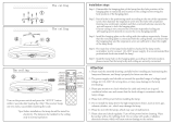
Discharge Direction Setting
• The discharge direction can be selected as shown below.
SELECTING THE MOUNTING
POSITION
Especially, the installation place is very important for the split type air
conditioner because it is very diffi cult to move from place to place after
the fi rst installation.
Decide the mounting position together with the customer as follows:
WARNING
Select installation locations that can properly support
the weight of the indoor. Install the units securely so that
they do not topple or fall.
CAUTION
Do not install the indoor unit in the following areas:
Area with high salt content, such as at the seaside. It
will deteriorate metal parts, causing the parts to fall
or the unit to leak water.
Area fi lled with mineral oil or containing a large
amount of splashed oil or steam, such as a kitchen.
It will deteriorate plastic parts, causing the parts to
fall or the unit to leak water.
Area that generates substances that adversely affect
the equipment, such as sulfuric gas, chlorine gas,
acid, or alkali. It will cause the copper pipes and
brazed joints to corrode, which can cause refrigerant
leakage.
Area that can cause combustible gas to leak, contains
suspended carbon fi bers or fl ammable dust, or vola-
tile infl ammables such as paint thinner or gasoline.
If gas leaks and settles around the unit, it can cause
a fi re.
Area where animals may urinate on the unit or am-
monia may be generated.
Do not install where there is the danger of combustible
gas leakage.
Do not install the unit near heat source of heat, steam,
or fl ammable gas.
Install the indoor unit, outdoor unit, power supply cable,
transmission cable, and remote controller cable at least
1 m away from a television or radio receivers. The pur-
pose of this is to prevent TV reception interference or
radio noise. (Even if they are installed more than 1 m
apart, you could still receive noise under some signal
conditions.)
If children under 10 years old may approach the unit, take
preventive measures so that they cannot reach the unit.
Use the “Insulation kit for high humidity” (option), when
the condition under the roof is over 80% in humidity and
over 30°C in temperature. Otherwise, there is a risk of
condensation on the ceiling.
(1) Install the indoor unit on a place having a suffi cient strength so that it
withstands against the weight of the indoor unit.
(2) The inlet and outlet ports should not be obstructed; the air should be
able to blow all over the room.
(3) Leave the space required to service the air conditioner.
(4) A place from where the air can be distributed evenly throughout the
room by the unit.
(5) Install the unit where connection to the outdoor unit is easy.
(6) Install the unit where the connection pipe can be easily installed.
(7) Install the unit where the drain pipe can be easily installed.
(8) Install the unit where noise and vibrations are not amplifi ed.
(9) Take servicing, etc., into consideration and leave the spaces. Also
install the unit where the fi lter can be removed.
INSTALLATION PROCEDURE
Install the air conditioner as follows:
* Select the most appropriate airfl ow direction from 3 or 4 directions ac-
cording to the shape of the room and the installation position.
* When changing the number of outlets, we recommend using the optional
AIR OUTLET SHUTTER PLATE KIT to close the outlet.
* For the specifi c closing pattern, please refer to the attached AIR OUTLET
SHUTTER PLATE KIT'S MANUAL. (Do so before installing the decora-
tive panel as it will be installed on the body.)
* Be sure to make the function settings with the remote controller
according to the number of airfl ow outlets and the installed ceiling
height. (See 8 FUNCTION SETTING.)
(Continued to the next page)
(*1) This part is not furnished for AUT* series
OPTIONAL PARTS
PREPARATION BEFORE INSTALLATION
2
3. INSTALLING DRAIN PIPE
INDOOR UNIT INSTALLATION
(1) Positions of the ceiling opening, hanging bolt pitch, piping and ducts.
(unit: mm)
• Ceiling opening and hanging bolt pitch.
• Refrigerant piping and drain piping positions.
• Airfl ow split-fl ow duct and fresh air inlet positions.
NOTES:
Conduct proper insulation when connecting the split-fl ow ducts and
fresh air inlet.
(2) Setting the positions of hanging bolt and ceiling opening.
• Use an installation template (packaging top surface) to set the
positions of the hanging bolt and ceiling opening and drill holes.
(3) Hanging structure.
• Select a strong structure for the hanging location.
• If necessary, reinforce the hanging bolt with quakeproof columnar
support material to prevent shaking.
• Use hanging bolts of M8-M10.
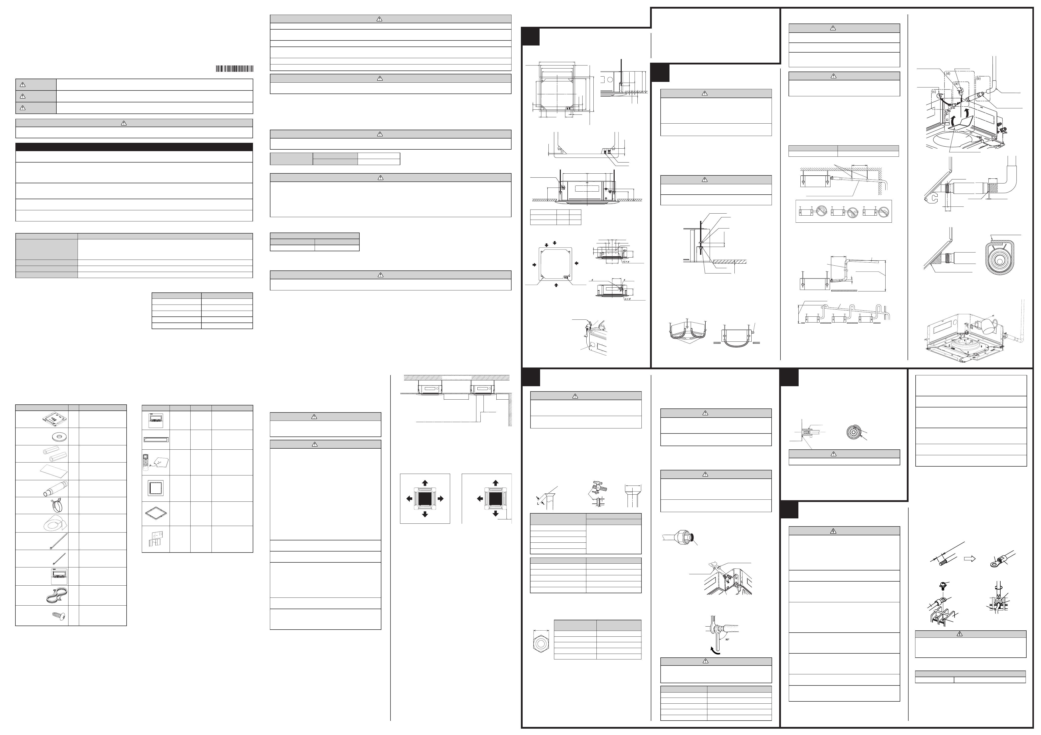
1. BODY INSTALLATION
1)
Install the attached washer and nut (prepared on site) onto the hanging bolt.
2) Hook the body onto the hanging bolt.
3) Adjust the dimensions of the ceiling surface from the body.
After installing the decorative panel, you can make fi ne adjustment
of the height of the body. For details, refer to the installation manual
of the decorative panel.
2. LEVELING
Using a level, or vinyl hose fi lled with water, fi ne adjust so that the body
is level.
Inclined installation so as the drain pipe side is higher may cause a mal-
function of the fl oat switch, and may cause water leakage.
Model No.
UTB
-
*
UD
UTR - YDZC
UTY - LRH*A1
Exterior
Summary
Unit control is per-
formed by wired
remote controller
Install the plate at outlet
when carrying out 3-way
direction operation.
Unit control is per-
formed by wireless
remote controller.
Parts name
Wired
remote
controller
Air outlet
shutter
plate
Wireless
remote
controller
and I, R,
receiver
unit
5 - 10 mm
VP25
35 mm
20 mm
NOTES:
Check for drainage
Pour about 1 liter of water from the position shown in the diagram or from
the airfl ow outlet to the dew tray. Check for any abnormalities such as
strange noises and whether the drain pump functions normally.
Working procedure
1) Install the attached drain hose to the drain port of the body. Install the
hose band from the top of the hose within the graphic display area.
2) Use vinyl adhesive agent to glue the drain piping (PVC pipe VP25)
which is prepared on site or elbow socket.
(Apply color adhesive agent evenly until the gauge line and seal)
3) Check the drainage. (See separate diagram)
4) Install the heat insulation.
5) Use the attached heat insulation to insulate the drain port and band
parts of the body.
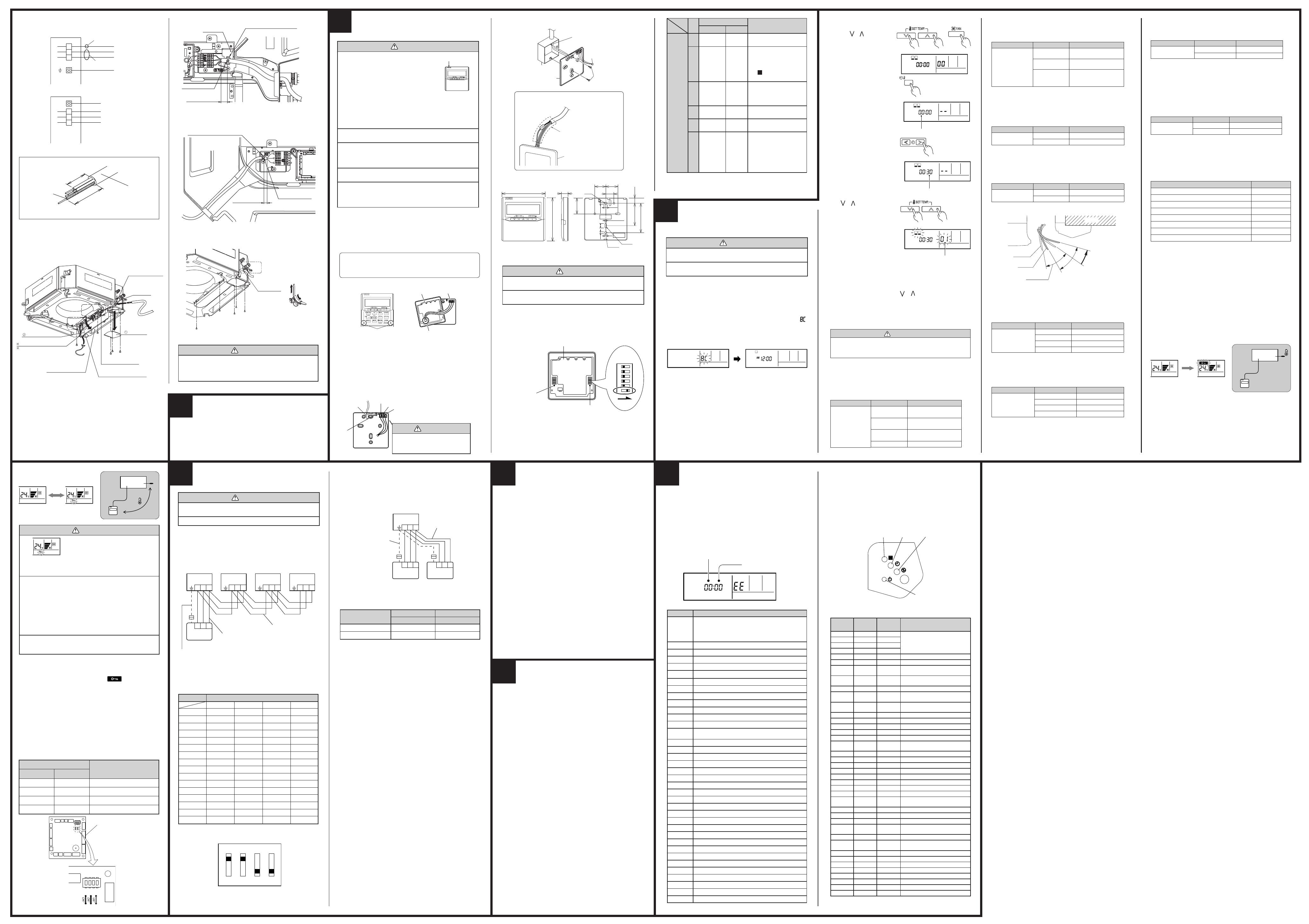
How to connect wiring to the terminals.
(1) Use ring terminals with insulating sleeves as shown in the fi gure
below to connect to the terminal block.
(2) Securely clamp the ring terminals to the wires using an
appropriate tool so that the wires do not come loose.
(3) Use the specifi ed wires, connect them securely, and fasten them
so that there is no stress placed on the terminals.
(4) Use an appropriate screwdriver to tighten the terminal screws.
Do not use a screwdriver that is too small, otherwise, the screw
heads may be damaged and prevent the screws from being
properly tightened.
(5) Do not tighten the terminal screws too much, otherwise, the screws
may break.
(6) See the table 1 for the terminal screw tightening torques.
Table 1
Strip 10 mm (13/32")
Sleeve
Screw with spe-
cial washer
Screw with spe-
cial washer
Ring terminal
Wire
Wire
Terminal
board
Terminal block
Ring terminal
Ring
terminal
ELECTRICAL WIRING
5
4
INSTALLING THE COUPLER
HEAT INSULATION
Body
Be sure to overlap the
insulation
Coupler heat insulation
No gap
Coupler heat insulation
After checking for gas leaks, insulate by wrapping insulation around the
two parts (gas and liquid) of the indoor unit coupling, using the coupler
heat insulation.
After installing the coupler heat insulation, wrap both ends with vinyl tape
so that there is no gap.
The pipes are shaped by your hands. Be careful not to collapse them.
Do not bend the pipes in an angle more than 90°.
When pipes are repeatedly bend or stretched, the material will harden,
making it diffi cult to bend or stretch them any more. Do not bend or
stretch the pipes more than three times.
CAUTION
To prevent breaking of the pipe, avoid sharp bends.
Bend the pipe with a radius of curvature of 150 mm or
over.
If the pipe is bent repeatedly at the same place, it will
break.
2. BENDING PIPES
To prevent gas leakage, coat the fl are
surface with alkylbenzene oil (HAB).
Do not use mineral oil.
(3) When the fl are nut is tightened properly by your hand, use a torque
wrench to fi nally tighten it.
Torque wrench
Holding spanner
Body side
CAUTION
Hold the torque wrench at its grip, keeping it in the
right angle with the pipe, in order to tighten the fl are nut
correctly.
(2) Centering the pipe against port on the indoor unit, turn the fl are nut
with your hand.
Flare nut Tightening torque
6.35 mm (1/4 in.) dia.
9.52 mm (3/8 in.) dia.
12.70 mm (1/2 in.) dia.
15.88 mm (5/8 in.) dia.
19.05 mm (3/4 in.) dia.
3. CONNECTION PIPES
Indoor unit
(1) Detach the caps and plugs from the pipes.
CAUTION
Be sure to apply the pipe against the port on the indoor
unit correctly. If the centering is improper, the fl are nut
cannot be tightened smoothly. If the fl are nut is forced
to turn, the threads will be damaged.
Do not remove the fl are nut from the indoor unit pipe
until immediately before connecting the connection pipe.
14 to 18 N·m (140 to 180 kgf·cm)
33 to 42 N·m (330 to 420 kgf·cm)
50 to 62 N·m (500 to 620 kgf·cm)
63 to 77 N·m (630 to 770 kgf·cm)
100 to 110 N·m (1,000 to 1,100 kgf·cm)
Connection pipe
(Liquid)
Connection pipe
(Gas)
CONNECTING THE PIPE
1. FLARING
(1) Cut the connection pipe to the necessary length with a pipe cutter.
(2) Hold the pipe downward so that cuttings will not enter the pipe and
remove the burrs.
(3) Insert the fl are nut (always use the fl are nut attached to the indoor
and outdoor units respectively) onto the pipe and perform the fl are
processing with a fl are tool.
Use the special R410A fl are tool, or the conventional fl are tool.
Check if [L] is fl ared uniformly
and is not cracked or scratched.
B
Die
A
Pipe
Width across
fl ats
6.35 mm (1/4 in.)
9.52 mm (3/8 in.)
12.70 mm (1/2 in.)
15.88 mm (5/8 in.)
19.05 mm (3/4 in.)
0 to 0.5
Pipe outside diameter
Dimension A
(mm)
Flare tool for R410A, clutch type
6.35 mm (1/4 in.)
9.52 mm (3/8 in.)
12.70 mm (1/2 in.)
15.88 mm (5/8 in.)
19.05 mm (3/4 in.)
9.1
13.2
16.6
19.7
24.0
Pipe outside diameter
Dimension B
(mm)
0
-0.4
When using conventional fl are tools to fl are R410A pipes, the dimension
A should be approximately 0.5 mm more than indicated in the table (for
fl aring with R410A fl are tools) to achieve the specifi ed fl aring. Use a
thickness gauge to measure the dimension A.
Pipe outside
diameter
Width across fl ats
of Flare nut
17 mm
22 mm
26 mm
29 mm
36 mm
6.35 mm (1/4 in.)
9.52 mm (3/8 in.)
12.70 mm (1/2 in.)
15.88 mm (5/8 in.)
19.05 mm (3/4 in.)
3
When sucking in the fresh air, please detach the insulation affi xed
to the drain pan.
Q’ty
1
8
2
1
1
1
1
3
1
1
1
2
Name and Shape
Template
(Carton top)
Washer
Coupler Heat
Insulation
Insulation
Drain Hose Assy
Hose Band Assy
Drain Pipe
Insulation
Binder (Large)
Binder (Small)
Wired Remote
Controller
Remote Controller
Cable(*1)
Tapping screw
(ø4 16)
Application
For installing indoor unit
For installing indoor unit
For indoor side pipe joint
For installing drain pipe
For installing drain pipe
For installing drain pipe
For installing drain pipe
For electrical wiring
For electrical wiring
For connecting the
remote controller
For installing the remote
controller
Copper pipes
It is necessary to use seamless copper pipes and it is desirable that the
amount of residual oil is less than 40 mg/10 m. Do not use copper pipes
having a collapsed, deformed or discolored portion (especially on the interior
surface). Otherwise, the expansion valve or capillary tube may become
blocked with contaminants.
As an air conditioner using R410A incurs pressure higher than when
using conventional refrigerant, it is necessary to choose adequate materials.
Thicknesses of copper pipes used with R410A are as shown in the table.
Never use copper pipes thinner than that in the table even when it is
available on the market.
Thicknesses of Annealed Copper Pipes (R410A)
Pipe outside diameter Thickness
6.35 mm (1/4 in.) 0.80 mm
9.52 mm (3/8 in.) 0.80 mm
12.70 mm (1/2 in.) 0.80 mm
15.88 mm (5/8 in.) 1.00 mm
19.05 mm (3/4 in.) 1.20 mm
For authorized service personnel only.
WARNING
For the air conditioner to operate satisfactorily, install it as outlined in this installation instruction sheet.
Connect the indoor unit and outdoor unit with the air conditioner piping and cables available from our standards parts. This
installation instruction sheet describes the correct connections using the installation set available from our standard parts.
Installation work must be performed in accordance with national wiring standards by authorized personnel only.
If refrigerant leaks while work is being carried out, ventilate the area. If the refrigerant comes in contact with a fl ame, it pro-
duces a toxic gas.
Do not use an extension cable.
Do not turn on the power until all installation work is complete.
CAUTION
This installation instruction sheet describes how to the indoor unit only.
To install the outdoor unit, refer to the installation instruction sheet included with the outdoor unit.
Be careful not to scratch the air conditioner when handling it.
After installation, explain correct operation to the customer, using the operating manual.
Let the customer keep this installation instruction sheet because it is used when the air conditioner is serviced or moved.
CONNECTION PIPE REQUIREMENT
CAUTION
Refer to the installation instruction sheet of the outdoor unit for description of the length of connecting pipe or for difference
of its elevation.
Diameter
Liquid 9.52 mm (3/8 in.)
Gas 15.88 mm (5/8 in.)
Use pipe with water-resistant heat insulation.
CAUTION
Install heat insulation around both the gas and liquid pipes. Failure to do so may cause water leaks.
Use heat insulation with heat resistance above 120 °C. (Reverse cycle model only)
In addition, if the humidity level at the installation location of the refrigerant piping is expected to exceed 70%, install heat
insulation around the refrigerant piping. If the expected humidity level is 70-80%, use heat insulation that is 15 mm or thicker
and if the expected humidity exceeds 80%, use heat insulation that is 20 mm or thicker.
If heat insulation is used that is not as thick as specifi ed, condensation may form on the surface of the insulation.
In addition, use heat insulation with heat conductivity of 0.045 W/(m·K) or less (at 20 °C).
ELECTRICAL REQUIREMENT
Connection cable (mm
2
)
MAX. MIN.
2.5 1.5
Use conformed cable with Type 60245 IEC57.
Install all electrical works in accordance to the standard.
Install the disconnect device with a contact gap of at least 3 mm in all poles nearby the units. (Both indoor unit and outdoor unit)
CAUTION
Be sure to execute the electrical work according to the Lows of each country and the Installation Instructions.
In addition, be sure to set as exclusive line and use the rated voltage and circuit breaker.
This product can be installed at a height of up to 4.2 m (30Type : 3.6 m).
However, if the heights of the ceiling is higher than 3.2 m or lower than 2.7 m,
it is necessary to set the position from remote controller.
(See 8 FUNCTION SETTING.)
Floor
Obstruction
1,500 mm
or more
1,800 mm or more
1,000 mm
or more
3,000 mm or more
Strong and durable ceiling
4 DIRECTION
100 mm
or more*
3 DIRECTION
*Please ensure suffi cient maintenance space during installation.
A
B
20 - 45 mm
20 - 45 mm
50 mm
200 mm
130 mm
130 mm
699 mm (Hanging bolt pitch)
950 mm (Panel frame)
860 - 910 mm (Ceiling opening)
840 mm (Body frame)
795 mm (Hanging bolt pitch)
20 - 45 mm
50 - 100 mm
140 - 145 mm
10 mm
40 mm
20 - 45 mm
80 mm
130 mm
840 mm (Body frame)
860 - 910 mm (Ceiling opening)
950 mm (Panel frame)
10 mm
80 mm
60 mm278 mm358 mm
140 mm
180 mm
200 mm
Gas pipe
Liquid pipe
Drain pipe
(Connect the attached
drain hose)
Model A B
24LB 246 256
30/36/45/54LB 288 298
88 mm
70 mm
250 mm
352 mm
100 mm
83 mm83 mm
90 mm
100 mm
185 mm
185 mm
Airfl ow split-fl ow duct connecting port
Airfl ow split-fl ow duct connecting port
Refrigerant
pipe
Cut out
Cut out
Detailed diagram of branched duct connecting port
(4 sides)
Fresh air inlet position
2.5 mm hole
2.5 mm hole
Burling hole pitch
Fresh air inlet position
Drain pipe
Airfl ow split-fl ow duct
connecting port
Airfl ow split-fl ow duct
connecting port
Insulation
Fresh air inlet position
CAUTION
Do not use mineral oil on fl ared part. Prevent mineral oil
from getting into the system as this would reduce the
lifetime of the units.
While welding the pipes, be sure to blow dry nitrogen
gas through them.
WARNING
Install the air conditioner in a location which can with-
stand a load do at least fi ve times the weight of the main
unit and which will not amplify sound or vibration. If the
installation location is not strong enough, the indoor
unit may fall and cause injuries.
If the job is done with the panel frame only, there is a risk
that the unit will come loose. Please take care.
10~15
After installing the body,
tighten the nuts.
Hanging bolt
Nut A
Washer
Washer
Nut B (Double Nut)
30 or more
CAUTION
Must fi t tightly against body without any gap.
WARNING
Electrical work must be performed in accordance with
this Manual by a person certifi ed under the national or
regional regulations. Be sure to use a dedicated circuit
for the unit.
An insuffi cient power supply circuit or improperly
performed electrical work can cause serious accidents
such as electric shock or fi re.
Before starting work, check that power is not being
supplied to the indoor unit and outdoor unit.
Use the included connection cables and power cables
or ones specifi ed by the manufacturer. Improper
connections, insuffi cient insulation, or exceeding the
allowable current can cause electric shock or fi re.
For wiring, use the prescribed type of wires, connect
them securely, making sure that there are no external
forces of the wires applied to the terminal connec-
tions. Improperly connected or secured wires can
cause serious accidents such as overheating the
terminals, electric shock, or fi re.
Do not modify the power cables, use extension cables,
or use any branches in the wiring. Improper connec-
tions, insuffi cient insulation, or exceeding the allow-
able current can cause electric shock or fi re.
Match the terminal board numbers and connection
cable colors with those of the outdoor unit.
Erroneous wiring may cause burning of the electric
parts.
Connect the connection cables fi rmly to the terminal
board. Imperfect installation may cause a fi re.
Always fasten the outside covering of the connection
cable with the cable clamp. (If the insulator is chafed,
electric leakage may occur.)
Install the knob
faces upward
Attached drain hose
heat insulation
Attached
hose band
Locally arranged
vinyl pipe
Attached drain hose
Attached heat insulation
Applying area
of adhesive
Hose band
Gauge line
Make sure there are no gaps
4 mm or less
Wind the attached heat insulation
around the hose band
Make sure the alignment
is on top
(a) Top view
(c) Top view
(d) Hose opening view
(b) Side view
WARNING
Use ring terminals and tighten the terminal screws to
the specifi ed torques, otherwise, abnormal overheating
may be produced and possibly cause heavy damage
inside the unit.
Tightening torque
M4 screw 12 to 18 N·m (12 to 18 kgf·cm)
Vinyl hoses
Drain pipe
CAUTION
Do not apply adhesive agent on the drain port of the
body. (Use the attached drain hose and connect the
drain piping)
NOTES: Install the drain pipe.
Install the drain pipe with downward gradient (1/50 to 1/100) and so
there are no rises or traps in the pipe.
Use general hard polyvinyl chloride pipe (VP25) [outside diameter
32 mm] and connect it with adhesive (polyvinyl chloride) so that there
is no leakage.
When the pipe is long, install supporters.
Do not perform air bleeding.
Always heat insulate the indoor side of the drain pipe.
If it is impossible to have suffi cient gradient of pipe, perform drain
lift-up.
Pipe size
Drain pipe VP25 (O.D. 32 mm)
Hanging fi ttings
1.5 to 2 m
VP25 (O.D. 32 mm)
Downward gradient 1/100 to 1/50
Rise
PROHIBITED:
Trap
Air bleeding
When lifting up drain:
• Height of inclined pipe should be less than 850 mm from the ceiling.
A rise dimension over this range will cause leakage.
• Lift up the pipe vertically at the position of 300 mm or less from the
unit.
300 mm or less
VP25 (O.D. 32 mm)
local arrangement
850 mm or less
Horizontal or up-
ward gradient
Downward gradient
1/100 to 1/50
VP30 (O.D. 38 mm) or more
Downward gradient 1/100 to 1/50
850 mm or less
Wide
panel
UTG-AGYA-W
UTG-BGYA-W
UTZ-KXRA
UTZ-KXGA
UTZ-KXGB
Panel
spacer
Insulation
kit for high
humidity
Wide panel hides the
gap between the ceiling
hole and the Cassette
grille.
Installation in a space
of 56 mm or greater is
possible by using panel
spacer when the height
behind the ceiling is low.
Install when the under
roof condition is expect-
ed to be the humidity of
over 80 % and the tem-
perature of over 30 °C.
Securely install the electrical box cover on the unit. An
improperly installed electrical box cover can cause se-
rious accidents such as electric shock or fi re through
exposure to dust or water.
Install sleeves into any holes made in the walls for wir-
ing. Otherwise, a short circuit could result.
Install a ground leakage breaker. In addition, install
the ground leakage breaker so that the entire AC main
power supply is cut off at the same time. Otherwise,
electric shock or fi re could result.
Install a ground leakage breaker.
If a ground leakage breaker is not installed, it may
cause electric shock or fi re.
Always connect the ground wire.
Improper grounding work can cause electric shocks.
Install the remote controller wires so as not to be
direct touched with your hand.
WARNING
Do not insert the drain piping into the sewer where sul-
furous gas occurs. (Heat exchange erosion may occur)
Insulate the parts properly so that water will not drip
from the connection parts.
Check for proper drainage after the construction by us-
ing the visible portion of transparent drain port and the
drain piping fi nal outlet on the body.
WARNING
Perform fi nal tightening by tightening the double nut
fi rmly.
Be sure to install the body horizontally and adjust the
height below the body and the ceiling surface properly.