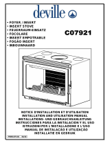
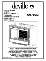
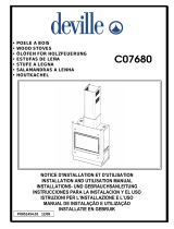
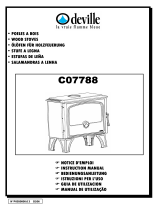
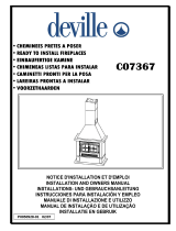
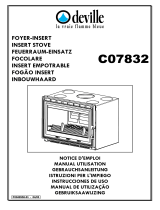
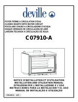
Page is loading ...

F
NOTICE D’INSTALLATION POELE A BOIS
2 - 5
GB
WOOD STOVE INSTALLATION MANUAL
6 - 9
D
ANLEITUNG ZUR INSTALLATION EINES OFFENS
FUR HOLZFEUERUNG
10 - 13
I
ISTRUZIONI PER L’INSTALLAZIONE STUFA A LEGNA
14 - 17
E
MANUAL DE INSTRUCCIONES ESTUFA DE LEÑA
18 - 21
P
MANUAL DE INSTALAÇÃO FOGÃO A LENHA
22 - 25
N° P0050776.0
9
0
7
/
1
0

2
F
Nous vous conseillons de lire attentivement, et au complet, le texte de la notice afin de tirer le meilleur usage et la
plus grande satisfaction de votre appareil DEVILLE.
Le non-respect des instructions de montage, d’installation et d’utilisation entraîne la responsabilité de celui qui
les effectue.
CET APPAREIL DOIT ETRE INSTALLE CONFORMEMENT AUX SPECIFICATIONS DES D.T.U. EN
VIGUEUR.
Toutes les réglementations locales et nationales, ainsi que les normes européennes, doivent être
respectées lors de l’utilisation de l’appareil.
L’appareil ne doit pas être modifié.
L’INSTALLATION PAR UN PROFESSIONNEL QUALIFIE EST RECOMMANDEE.
Ces poêles sont conformes aux exigences essentielles de la directive 89/106/CEE Produits de Construction suivant
l’annexe ZA de la norme EN 13240.
Ce sont des appareils de chauffage continu à combustion sur grille fonctionnant exclusivement au bois, à chambre de
combustion semi fermée.
1. CONDITIONS D’INSTALLATION DE L’APPAREIL
L'installation ne devra pas être modifiée par l'utilisateur.
Nous rappelons ci-après les recommandations élémentaires à respecter. Le DTU 24-2-2 décrit de façon complète les
dispositions nécessaires concernant le circuit d’évacuation des fumées.
1.1 - DöNOMINATION DES DIVERSES PARTIES DU CIRCUIT D'öVACUATION DES FUMöES (Fig. 1)
1.2 - NATURE ET CARACTöRISTIQUES DIMENSIONNELLES DU CONDUIT DE FUMöE AUQUEL DOIT ÊTRE
OBLIGATOIREMENT RACCORDö L'APPAREIL
1.2.1 Nature du conduit de fumée
Référence Puissance nominale Tirage Débit massique des fumées
Température des fumées Poids net
C07706 9 KW 6,5 g/s 306 °C 136 kg
C07708 9 KW 6,1 g/s 270 °C 87 kg
C07709 9 KW 6,1 g/s 270 °C 101 kg
C07726 9 KW 6,5 g/s 306 °C 143 kg
C07727 9 KW 6,5 g/s 306 °C 156 kg
C07728 12 KW 9,2 g/s 353 °C 171 kg
C07729 9 KW 6,5 g/s 306 °C 155 kg
C07750 9 KW 6,1 g/s 270 °C 95 kg
C07751 7 KW 6,2 g/s 288 °C 54 kg
C07753 14 KW 8,2 g/s 295 °C 130 kg
C07762 9 KW 6,1 g/s 270 °C 71 kg
C07780 13 KW 10,6 g/s 305 °C 114 kg
C07782 9 KW 6,1 g/s 270 °C 104 kg
C07783 14 KW 8,2 g/s 295 °C 113 kg
C07784 14 KW 8,2 g/s 295 °C 130 kg
C07785 9 KW 6,1 g/s 270 °C 100 kg
C07787 9 KW 6 g/s 310 °C 94 kg
C07788 9 KW 6 g/s 310 °C 100 kg
C07789 9 KW 6,1 g/s 270 °C 84 kg
C07790 9 KW 6,1 g/s 270 °C 91 kg
C07794 11 KW 8,1 g/s 306 °C 120 kg
C07794-FP 9 KW 7.5 g/s 319 °C 118 kg
C07796 11 KW 8,1 g/s 306 °C 156 kg
C07796-FP 9 KW 7.5 g/s 319 °C 154 kg
C07799 9 KW 6,1 g/s 270 °C 73 kg
C077AA 9 KW
12 Pa
6,1 g/s 270 °C 78 kg

6
GB
You are advised to read carefully and in full the information provided in order to get the best performance - and
the most satisfaction - out of your DEVILLE stove.
Failure to comply with the assembly, installation and operating instructions places all responsibility upon the
person(s) concerned.
INSTALLATION SHOULD COMPLY WITH CURRENT DTU (FRENCH CODE OF PRATICE)
SPECIFICATIONS.
All local, national, and european regulations must be respected when using this appliance.
The appliance must not be modified.
INSTALLATION BY A QUALIFIED TRADESMAN IS RECOMMENDED.
Reference Power rating Draft
Mass discharge of smoke Temperature of smoke Net weight
C07706 9 KW 6,5 g/s 306 °C 136 kg
C07708 9 KW 6,1 g/s 270 °C 87 kg
C07709 9 KW 6,1 g/s 270 °C 101 kg
C07726 9 KW 6,5 g/s 306 °C 143 kg
C07727 9 KW 6,5 g/s 306 °C 156 kg
C07728 12 KW 9,2 g/s 353 °C 171 kg
C07729 9 KW 6,5 g/s 306 °C 155 kg
C07750 9 KW 6,1 g/s 270 °C 95 kg
C07751 7 KW 6,2 g/s 288 °C 54 kg
C07753 14 KW 8,2 g/s 295 °C 130 kg
C07762 9 KW 6,1 g/s 270 °C 71 kg
C07780 13 KW 10,6 g/s 305 °C 114 kg
C07782 9 KW 6,1 g/s 270 °C 104 kg
C07783 14 KW 8,2 g/s 295 °C 113 kg
C07784 14 KW 8,2 g/s 295 °C 130 kg
C07785 9 KW 6,1 g/s 270 °C 100 kg
C07787 9 KW 6 g/s 310 °C 94 kg
C07788 9 KW 6 g/s 310 °C 100 kg
C07789 9 KW 6,1 g/s 270 °C 84 kg
C07790 9 KW 6,1 g/s 270 °C 91 kg
C07794 11 KW 8,1 g/s 306 °C 120 kg
C07794-FP
9 KW 7.5 g/s 319 °C 118 kg
C07796 11 KW 8,1 g/s 306 °C 156 kg
C07796-FP
9 KW 7.5 g/s 319 °C 154 kg
C07799 9 KW 6,1 g/s 270 °C 73 kg
C077AA 9 KW
12 Pa
6,1 g/s 270 °C 78 kg
These wood stoves comply with the essential requirements of the directive 89/106/CEE Construction Products
according to appendix ZA of the standard EN 13240.
These are constant heating system with grating combustion designed exclusively for wood burning, inside a semi-closed
combustion chamber.
1. GENERAL CONDITIONS
The user should not make any modifications to this appliance.
Basic recommendations are given below. DTU 24-2-2 describes in detail the procedures required regarding the smoke
venting circuit.
1.1 - DIAGRAM SHOWING SMOKE FLUE COMPONENTS (Fig. 1)
1.2 - CHARACTERISTICS AND DIMENSIONS OF SMOKE FLUE TO WHICH CONNECTION OF THE STOVE IS
MANDATORY
1.2.1 Smoke flue

7
1.2.1.1 New flue
The following materials must be used :
. Fireclay flue liners compliant with French Standard NF P 51-311.
. Concrete flue liners compliant with NF P 51-321.
. Composite metal ducts compliant with NF D 35-304 and NF D 35-303.
. Fireclay bricks compliant with NF P 51-301.
. Refractory bricks compliant with NF P 51-302.
Using already insulated materials avoids having to insulate during installation, which is especially useful where stacks
linings are concerned.
1.2.1.2 Existing flue
Whoever is doing the installation is responsible for existing work, and therefore should check the flue and carry out any
work required to ensure it is in proper working order and that it complies with current regulations.
Sweep the flue and then thoroughly inspect it to check the following :
. the flue’s suitability for its intented use
. stability
. lack of any obstruction and absence of leaks (DTU 24-1, Appendix II).
If the flue is not compatible with the stove, install the required tubing using an approved and certificated method (in
France, a method that has an “Avis Technique” certificate), or else put in a new flue.
1.2.2 Minimum flue section
Square or oblong liners : minimum section 2,5 dm
2
Circular ducts : mimimum diameter 153 mm.
1.2.3 General recommendations
A good flue should be built using materials that do not conduct much heat so that it stays hot. The casing should be such
as to limit the external surface temperature as follows :
. 50°C in living areas
. 80°C in non-living.
The flue should be completely smoketight, smooth and stable.
There should be no sudden variations in section : angle in relation to the vertical should be less than 45°.
The stake should extend at least 0,4 m from the ridge of the roof and adjacent roofs.
Two stoves should not be connected to the same flue.
Where the stove itself is installed, the flue should come down to at least 50 mm above floor level.
The inside face should be at least 16 cm away from any wood or combustible material.
The flue liners should be placed the male part down, in order to avoid runs to the outer surface.
The flue should include no more than two changes in alignment (i.e. not more than one non-vertical section).
Flue cased in brickwork :
. No angle of change of alignment should exceed 45° over a total flue height not exceeding 5 metres. For any greater
flue height, the angle of any change of alignment is limited to 20°.
Insulated metal flue :
. No angle of change of alignment should exceed 45° and height form top to bottom of any such angled section should
not exceed 5 metres. Total flue height is unrestricted.
Smoketightness, insulation, runs through ceilings and floors and safe distances to flue should be in strict compliance with
DTU 24-2-2.
1.3 - CHARACTERISTICS OF CONNECTOR FITTING BETWEEN STOVE AND FLUE
First, it is essential to install a connector between the stove and the flue. The connector should use rigid or flexible
multifuel conduit approved for direct connection to a closed source of heat.

8
The following materials are prohibited
: aluminium, aluminized and galvanized steel.
The following materials are approved : black plate (min. thickness 2 mm), enamelled plate (min. thickness 0.6 mm) and
stainless steel (min. thickness 0.4 mm).
The connector fitting should be visible over its entire length and capable of being swep mechanically. Expansion should
not adversely affect the conduit intake or discharge junctions or its own mechanical stability or that of the main smoke
flue. Its design, and more especially its connection to the smoke flue, should be such as to prevent the accumulation of
soot, notably during sweeping.
Connections to both the stove and the flue should strictly comply with DTU 24.2.2 and the conduit manufacturer's
specifications and should include all the fittings recommended (end fittings, connecting pieces etc...).
If the connector is to be horizontal, there should be an ascending slope of 5 cm per metre.
1.4 - DRAUGHT REQUIREMENTS
Draught is measured on the connector duct about 50 cm after the stove outlet.
The draught required for efficient working with the door closed is as follow :
. 6 Pa on slow (0,6 mm WG)
. 12 Pa on normal (1,2 mm WG)
The installation of a damper is strongly recommended.
A damper ensures an efficient operation, even where draught requirements are considerable (high flue and casing). The
damper should be visible and readily accessible (Fig. 2) and installed in the same room as the stove.
The damper does not habe any effect on the stove when the door is open.
1.5 - VENTILATION OF AREA IN WHICH STOVE IS INSTALLED
To ensure the stove works properly, air is required in addition to the air required for the statutory ventilation rate. This
additional air is compulsory when the dwelling is equipped with a mechanical ventilation system.
The air intake should be positioned either directly to the outside or in an area having ventilation to the outside. The intake
should be equipped with a protective grill.
The air outlet should be as near as possible to the stove. The user should be able to close it off when it comes
out directly into the room. While the appliance is being used, make sure that it is free of any obstructions.
The section of the air inlet must be at least equal to one quarter of the section of the chimney flue with a minimum of 50
cm² for a power rating less than or equal to 8 kW, and 70 cm² for a power rating between 8 KW and 16 KW.
It may be necessary to stop the mechanical ventilation fan so as to prevent smoke coming back into the room when the
door is opened.
1.6 – WALLS IN THE VICINITY OF THE APPLIANCE
The stove should be located at least 300 mm from the rear and side walls of the room and from any combustible
materials.
In order to protect the floor from heat radiation and possible falling combustible, install the unit on reflective metal
shielding (or on a tiled floor) which covers the entire surface underneath and in front of the unit.
The appliance must be set up on a floor with a sufficient bearing capacity. If the existing construction does not comply
with this prior requirement, appropriate measures must be taken to allow the floor to bear the appliance, such as setting
up a load distribution plate.

9
1.7 - GLOBAL TERMS OF WARRANTY
1. TERMS AND CONDITIONS
Apart from the legal warranty, particularly for latent defects, Deville guarantees to deliver the furniture in case of
obvious defects or non-conformity to the ordered furniture.
Without prejudice to the provisions that are to be taken concerning the carrier, claims on delivery of furniture
concerning the obvious defects or the non conformity, must be issued by the Buyer in writing a registered letter with
confirmation of receipt to Deville company with in 5 days after noticing the defect. It is up to the Buyer to prove the
reality of the noticed defects and irregularities. The Buyer must let Deville every opportunity of noticing any of those
defects and irregularities in order to salve then.
The Buyer must also keep the non standard supplies at the disposal of Deville, according to the instructions of the
latter. All return of material, for any reasons, should be subject to a formal pre – agreement from Deville.
2. EXTEND
The warranty of Deville covers, except for any compensation or for damages, the free replacement or repairing of
supplier the part acknowledged as being defected (except for wear and tear parts ) by its services to the exclusion of
the fees for the workplace, for the removal and for the shipping.
On enamelled equipments, appliances, crackles are never considered as a manufacturing defect. They are due to
the difference of expansion of iron enamel or cast-iron enamel and don’t alter the adherence.
Paid replacement parts are warranted for a six-month period from the invoicing date, any additional warranty agreed
by a retailer from Deville doesn’t commit Deville. Whenever claiming under a warranty, the guarantee with the stamp
from the retailer Deville is strictly required. The above guarantee must be produced for any demand to repair the
appliance under warranty, or a detachable slip or coupon of any such guarantee must, according to the own
organisation of Deville, be returned to the latter within the required time. For lack of this, the date on the invoice
issued by Deville can’t be taken into account. The interventions under warranty can’t have the effect of continuing the
warranty.
3. WARRANTY PERIOD
The period of the agreed warranty ensured by Deville is for 2 years (5 years for the fireplace heating body) from the
date when the appliance was purchased by the user, subject to the fact the claims -forecast by the above conditions-
were done within the time allowed. The repairing, the replacement or the alteration of parts under the warranty period
can neither have the effect of continuing the period of the latter, not get to any compensation for any fees, for late
delivery, accidents or any such damages.
4. EXCLUSION
The warranty is unavailable for the following cases, without this list being exhaustive :
Fitting out, fitting out and assembling of appliances not due to Deville.
Consequently Deville can’t be considered as responsible for damages or supplies, or accidents to persons due to
local laws and regulations (for example the fact that there is no linking to the earth ground connection or a wrong
drought of a fitting out).
Fair wear and tear of the supplies or abnormal use of the supplies including the case of industrial or trading use or a
use of the supplies in different conditions from the ones it was built for. It is, for example, of non respect of the
conditions described in the directions issued by Deville : display to outside conditions damaging the appliance ; such
as excessive dampness or abnormal change of the electrical tension. Malfunction, damage or accident due to a
shock, a drop, a carelessness, a failure of supervision or of service from the Buyer.
Any alteration, change or intervention made by a member of the staff or a company that is not approved by Deville,
or manufactured with replacement parts that are not genuine or not approved by the manufacturer.
5. SPECIAL TERMS OF WARRANTY
These terms add and define the above general terms of warranty and come first to the former, refer to the enclosed
leaf untitled : “special terms of sales Deville - warranty”.

10
D
Zur optimalen und zufriedenstellenden Nutzung Ihres Deville-Feuerraum-Einsatzes empfehlen wir Ihnen, die
vorliegende Anleitung in ihrer Gesamtheit vollständig durchzulesen.
Personen, welche die Richtlinien fûr Montage, Installation und Verwendung nicht beachten, sind für eventuelle
Folgen selbst verantwortlich.
DER OFEN MUSS UNTER BEACHTUNG GELTENDER TECHNISCHER VORSCHRIFTEN INSTALLIERT
WERDEN.
Alle örtlichen und nationalen vorschriften sowie die europäischen Normen müssen bei der Benutzung
des Gerätes beachtet werden.
Das Gerät darf nicht verandert werden.
ES WIRD EMPFOHLEN, DIE INSTALLATION DURCH EINE FACHKRAFT DURCHFUHREN ZU
LASSEN.
Referenzen
Leistung Zug
Rauchmassenstrom Rauchtemperatur Nettogewicht
C07706 9 KW 6,5 g/s 306 °C 136 kg
C07708 9 KW 6,1 g/s 270 °C 87 kg
C07709 9 KW 6,1 g/s 270 °C 101 kg
C07726 9 KW 6,5 g/s 306 °C 143 kg
C07727 9 KW 6,5 g/s 306 °C 156 kg
C07728 12 KW 9,2 g/s 353 °C 171 kg
C07729 9 KW 6,5 g/s 306 °C 155 kg
C07750 9 KW 6,1 g/s 270 °C 95 kg
C07751 7 KW 6,2 g/s 288 °C 54 kg
C07753 14 KW 8,2 g/s 295 °C 130 kg
C07762 9 KW 6,1 g/s 270 °C 71 kg
C07780 13 KW 10,6 g/s 305 °C 114 kg
C07782 9 KW 6,1 g/s 270 °C 104 kg
C07783 14 KW 8,2 g/s 295 °C 113 kg
C07784 14 KW 8,2 g/s 295 °C 130 kg
C07785 9 KW 6,1 g/s 270 °C 100 kg
C07787 9 KW 6 g/s 310 °C 94 kg
C07788 9 KW 6 g/s 310 °C 100 kg
C07789 9 KW 6,1 g/s 270 °C 84 kg
C07790 9 KW 6,1 g/s 270 °C 91 kg
C07794 11 KW 8,1 g/s 306 °C 120 kg
C07794-FP
9 KW 7.5 g/s 319 °C 118 kg
C07796 11 KW 8,1 g/s 306 °C 156 kg
C07796-FP
9 KW 7.5 g/s 319 °C 154 kg
C07799 9 KW 6,1 g/s 270 °C 73 kg
C077AA 9 KW
12 Pa
6,1 g/s 270 °C 78 kg
Diese Öfen sind den wesentlichen Forderungen der Direktive 89 / 106 / CEE vom der Nebengebäude ZA der Norm EN
13240 folgenden Bau Hergestellt entsprechend.
Es sind handelt sich um ein Heizgerät, das im Dauerbetrieb auf Rost ausschließlich mit Holz, bei halb-geöffnetem
Brennraum beschickt wird.
1. VORAUSSETZUNGEN FUR DIE INSTALLATION DES OFFENS
Die Installation darf vom Benutzer nicht abgeändert werden.
Wir stellen nachfolgend die grundlegenden, bei der Installation einzuhaltenden Empfehlungen zusammen. Die
technische Vorschrift DTU 24-2-2 beschreibt vollständig alle notwendigen Vorrichtungen zur Abführung von Rauchgasen.
1.1 - BEZEICHNUNG DER VERSCHIEDENEN TEILE EINES RAUCHGAS-ABFUHRUNGSSYSTEMS (Abb. 1)
1.2 - ART UND ABMESSUNGEN DES KAMINSCHACHTS, AN DEM DER OFFEN ANGESCHLOSSEN WERDEN MUSS
1.2.1 Art des Kaminschachts

14
I
Si consiglia di leggere attentamente le seguenti istruzioni per potere sfruttare al massimo e nel modo più
soddisfacente il Vostro focolare DEVILLE.
Si declina ogni responsabilità per il mancato rispetto delle istruzioni di montaggio, installazione e utilizzazione.
L’IMPIANTO DEVE ESSERE INSTALLATO IN CONFORMITA’ DELLE NORME D.T.U. IN VIGORE.
Ogni regolamentazione locale e nazionale, cosi’ come le norme europee vanno rispettate quando si usa
l’apparecchio.
L’apparecchio non deve essere modificato.
L’INSTALLAZIONE DELL’IMPIANTO DEVE ESSERE EFFETTUATA DA PERSONALE QUALIFICATO.
Queste stufe sono conformi alle esigenze essenziali della direttiva 89/106/CEE Prodotti di Costruzione secondo
l'allegato ZA della normativa EN 13240.
Sono apparecchi di riscaldamento continuo a combustione su griglia funzionante esclusivamente a legna, con camera di
combustione semiaperta.
1. CONDIZIONI PER L’INSTALLAZIONE DELL’IMPIANTO
Non possono essere apportate modifiche all’impianto.
Di seguito vengono indicate le raccomandazioni elementari che dovranno essere rispettate. La norma DTU 24-2-2
descrive in modo esauriente le disposizioni relative al circuito di evacuazione del fumi.
1.1 - DENOMINAZIONE DELLE VARIE PARTI DEL CIRCUITO DI EVACUAZIONE DEI FUMI (Fig. 1)
1.2 - NATURA E DIMENSIONI DELLA CANNO FUMARIA SULLA QUALE DEVE ESSERE OBBLIGATORIAMENTE
COLLEGATO L’IMPIANTO
1.2.1 Natura della canna fumaria
Riferimenti Potenza nominale Tiraggio Portata massica dei fumi Temperatura dei fumi Peso netto
C07706 9 KW 6,5 g/s 306 °C 136 kg
C07708 9 KW 6,1 g/s 270 °C 87 kg
C07709 9 KW 6,1 g/s 270 °C 101 kg
C07726 9 KW 6,5 g/s 306 °C 143 kg
C07727 9 KW 6,5 g/s 306 °C 156 kg
C07728 12 KW 9,2 g/s 353 °C 171 kg
C07729 9 KW 6,5 g/s 306 °C 155 kg
C07750 9 KW 6,1 g/s 270 °C 95 kg
C07751 7 KW 6,2 g/s 288 °C 54 kg
C07753 14 KW 8,2 g/s 295 °C 130 kg
C07762 9 KW 6,1 g/s 270 °C 71 kg
C07780 13 KW 10,6 g/s 305 °C 114 kg
C07782 9 KW 6,1 g/s 270 °C 104 kg
C07783 14 KW 8,2 g/s 295 °C 113 kg
C07784 14 KW 8,2 g/s 295 °C 130 kg
C07785 9 KW 6,1 g/s 270 °C 100 kg
C07787 9 KW 6 g/s 310 °C 94 kg
C07788 9 KW 6 g/s 310 °C 100 kg
C07789 9 KW 6,1 g/s 270 °C 84 kg
C07790 9 KW 6,1 g/s 270 °C 91 kg
C07794 11 KW 8,1 g/s 306 °C 120 kg
C07794-FP
9 KW 7.5 g/s 319 °C 118 kg
C07796 11 KW 8,1 g/s 306 °C 156 kg
C07796-FP
9 KW 7.5 g/s 319 °C 154 kg
C07799 9 KW 6,1 g/s 270 °C 73 kg
C077AA 9 KW
12 Pa
6,1 g/s 270 °C 78 kg

18
E
Le aconsejamos leer atenta y completamente el texto de estas instrucciones con el fin de poder utilizar en las
mejores condiciones y con la mayor satisfacción el aparato DEVILLE que acaba de adquirir.
El incumplimiento de las instrucciones de montaje, de instalación y de uso implica la responsabilidad de quién
los efectuó.
ESTE ESTUFA DEBE INSTALARSE DE ACUERDO CON LAS ESPECIFICACIONES DE D.T.U.
VIGENTES.
Tiene que respetar todas las normativas locales y nacionales, asi como las normas europeas a la hora de
utilizar el aparato.
Esta prohibido modificar el aparato.
SE RECOMIENDA LA INSTALACIÓN POR UN PROFESIONAL CUALIFICADO.
Estas estufas están conforme con las exigencias esenciales de la directiva 89 / 106 / CEE Productos de Construcción
según el anexo ZA de la norma EN 13240.
Son aparatos de calefacción contínua de combustión sobre reja que funciona exclusivamente con leña y con cámara de
combustión semi-cerrada.
1. CONDICIONES DE INSTALACIÓN DE DE LA ESTUFA
El usuario no deberá modificar la instalación.
Recordamos a continuación las recomendaciones elementales que deben respetarse. La DTU 24-2-2 describe de
manera completa las disposiciones necesarias relativas al circuito de evacuación de humos.
1.1 - DENOMINACION DE LAS DIVERSAS PARTES DEL CIRCUITO DE EVACUACION DE HUMOS (Fig. 1)
1.2 - TIPO Y CARACTERISTICAS DIMENSIONALES DEL CONDUCTO DE HUMO A QUE DEBE CONECTARSE
OBLIGATORIAMENTE LA ESTUFA
Referencias Potencia nominal Tiro Producción de humos Temperatura de los humos Peso neto
C07706 9 KW 6,5 g/s 306 °C 136 kg
C07708 9 KW 6,1 g/s 270 °C 87 kg
C07709 9 KW 6,1 g/s 270 °C 101 kg
C07726 9 KW 6,5 g/s 306 °C 143 kg
C07727 9 KW 6,5 g/s 306 °C 156 kg
C07728 12 KW 9,2 g/s 353 °C 171 kg
C07729 9 KW 6,5 g/s 306 °C 155 kg
C07750 9 KW 6,1 g/s 270 °C 95 kg
C07751 7 KW 6,2 g/s 288 °C 54 kg
C07753 14 KW 8,2 g/s 295 °C 130 kg
C07762 9 KW 6,1 g/s 270 °C 71 kg
C07780 13 KW 10,6 g/s 305 °C 114 kg
C07782 9 KW 6,1 g/s 270 °C 104 kg
C07783 14 KW 8,2 g/s 295 °C 113 kg
C07784 14 KW 8,2 g/s 295 °C 130 kg
C07785 9 KW 6,1 g/s 270 °C 100 kg
C07787 9 KW 6 g/s 310 °C 94 kg
C07788 9 KW 6 g/s 310 °C 100 kg
C07789 9 KW 6,1 g/s 270 °C 84 kg
C07790 9 KW 6,1 g/s 270 °C 91 kg
C07794 11 KW 8,1 g/s 306 °C 120 kg
C07794-FP 9 KW 7.5 g/s 319 °C 118 kg
C07796 11 KW 8,1 g/s 306 °C 156 kg
C07796-FP 9 KW 7.5 g/s 319 °C 154 kg
C07799 9 KW 6,1 g/s 270 °C 73 kg
C077AA 9 KW
12 Pa
6,1 g/s 270 °C 78 kg

22
P
Aconsolhamos que leia com atenção, e totalmente, o texto do manual para obter o melhor uso a a maior
satisfação do seu aparelho DEVILLE.
O não cumprimento das instruções de montagem, instalação e utilização implica a responsabilidade de quem as
efectua.
ESTE APARELHO DEVE SER INSTALADO EM CONFORMIDAD COM AS ESPECIFICAÇÕES DOS DTU
EM VIGOR.
Todas as regulamentações locais e nacionais, assim que as normas europeias, devem ser respeitadas
para a utilização do aparelho.
O aparelho não deve-se modificar.
É RECOMENDADA A INSTALAÇÃO POR UM PROFISSIONAL QUALIFICADO.
Estas Salamandras são conformes com as exigências essenciais da directiva 89/106/CEE Produtos de Construção
seguinte com o anexo ZA da norma EN 13240.
São aparelhos de aquecimento contínuo com combustão sobre grelha e funcionamento exclusivamente a lenha, com
câmara de combustão meia fechada.
1. CONDIÇÕES DE INSTALAÇÃO DO APARELHO
A instalação não deverá ser modificada pelo utilizador.
Recordamos a seguir as recomendações elementares a respeitar. O DTU 24-2-2 descreve de maneira completa as
disposições necessariás relativas ao circuito de evacuação de fumos.
1.1 - DENOMINAÇÃO DAS DIVERSAS PARTES DO CIRCUITO DE EVACUAÇÃO DE FUMOS (Fig. 1)
1.2 - NATUREZA E CARACTERISTICAS DE DIMENSÕES DA CONDUTA DE FUMOS A QUE O APARELHO DEVE FICAR
OBRIGATORIAMENTE LIGADO
Referências Potência nominal Tiragem Débito da massa dos fumos Temperatura dos fumos
Peso
liquido
C07706 9 KW 6,5 g/s 306 °C 136 kg
C07708 9 KW 6,1 g/s 270 °C 87 kg
C07709 9 KW 6,1 g/s 270 °C 101 kg
C07726 9 KW 6,5 g/s 306 °C 143 kg
C07727 9 KW 6,5 g/s 306 °C 156 kg
C07728 12 KW 9,2 g/s 353 °C 171 kg
C07729 9 KW 6,5 g/s 306 °C 155 kg
C07750 9 KW 6,1 g/s 270 °C 95 kg
C07751 7 KW 6,2 g/s 288 °C 54 kg
C07753 14 KW 8,2 g/s 295 °C 130 kg
C07762 9 KW 6,1 g/s 270 °C 71 kg
C07780 13 KW 10,6 g/s 305 °C 114 kg
C07782 9 KW 6,1 g/s 270 °C 104 kg
C07783 14 KW 8,2 g/s 295 °C 113 kg
C07784 14 KW 8,2 g/s 295 °C 130 kg
C07785 9 KW 6,1 g/s 270 °C 100 kg
C07787 9 KW 6 g/s 310 °C 94 kg
C07788 9 KW 6 g/s 310 °C 100 kg
C07789 9 KW 6,1 g/s 270 °C 84 kg
C07790 9 KW 6,1 g/s 270 °C 91 kg
C07794 11 KW 8,1 g/s 306 °C 120 kg
C07794-FP 9 KW 7.5 g/s 319 °C 118 kg
C07796 11 KW 8,1 g/s 306 °C 156 kg
C07796-FP 9 KW 7.5 g/s 319 °C 154 kg
C07799 9 KW
12 Pa
6,1 g/s 270 °C 73 kg
C077AA 9 KW 6,1 g/s 270 °C 78 kg

26
Fig. 1

27
Fig. 2

28
Les descriptions et caractéristiques figurant sur ce document sont données à titre d'information et non d'engagement.
En effet, soucieux de la qualité de nos produits, nous nous réservons le droit d'effectuer,
sans préavis, toute modification ou amélioration.
***
******
***
Société Anonyme au capital de 6.404.454 €
R.C SEDAN 787 020 080 B - Sirène 787 020 080 00018
SIEGE SOCIAL
76 rue Forest - 08013 CHARLEVILLE-MEZIERES CEDEX
www.deville.fr
-
/
