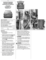
Reese 118715 is a T-Connector wiring kit that allows you to easily add a 4-Flat trailer connector to your vehicle. It is compatible with a variety of vehicles, including the Ford Escape. The kit includes everything you need for installation, including the T-Connector, wire, fuse holder, and hardware. The T-Connector plugs into the vehicle's taillight socket and provides a connection for the trailer's lights. The wire is then routed to the battery and connected to the fuse holder. The fuse holder protects the circuit from overloads.
Reese 118715 is a T-Connector wiring kit that allows you to easily add a 4-Flat trailer connector to your vehicle. It is compatible with a variety of vehicles, including the Ford Escape. The kit includes everything you need for installation, including the T-Connector, wire, fuse holder, and hardware. The T-Connector plugs into the vehicle's taillight socket and provides a connection for the trailer's lights. The wire is then routed to the battery and connected to the fuse holder. The fuse holder protects the circuit from overloads.


-
 1
1
-
 2
2
-
 3
3


Reese 118715 is a T-Connector wiring kit that allows you to easily add a 4-Flat trailer connector to your vehicle. It is compatible with a variety of vehicles, including the Ford Escape. The kit includes everything you need for installation, including the T-Connector, wire, fuse holder, and hardware. The T-Connector plugs into the vehicle's taillight socket and provides a connection for the trailer's lights. The wire is then routed to the battery and connected to the fuse holder. The fuse holder protects the circuit from overloads.
Ask a question and I''ll find the answer in the document
Finding information in a document is now easier with AI
in other languages
- français: Reese 118715 Guide d'installation
- español: Reese 118715 Guía de instalación
Related papers
-
Tekonsha 118549 Installation guide
-
-
-
-
-
-
-
-
-
Other documents
-
 Cequent T-Connector Installation guide
-
CURT 56120 Installation guide
-
Roadmaster Bulb and socket Operating instructions
-
-
Garmin STPc530 OEM,AM,Mopar,KA Kit Installation guide
-
 Kentrol 80710 Installation guide
-
Kicker 19418459 Owner's manual
-
-
Lund 30002 Owner's manual
-
Mopar K6862043 Installation Instructions Manual

