Page is loading ...

Digital Tach/Hourmeter with Overspeed Trip Point
Installation Instructions
for SHD45 Model
SHD-96113N
Revised 05-02
Section 20
(00-02-0776)
Description
The SHD45 is a microprocessor-based digital tachometer and hourmeter with an over-
speed trip point. The overspeed trip point can be connected as either a form
“B” relay
output or as a normally
open SCR output.
In Class I, Div. 2, hazardous locations the SHD45 form “B” relay contact is restricted for
use with Murphy non-incendive instruments. In non-hazardous locations the relay con-
tact may be used to switch resistive loads not exceeding 0.5 A @ 30 VDC or 125 VAC.
When connected as a normally open SCR, the output is rated 0.5 A, 350 VDC continu-
ous and can switch up to 3 A @ 350 VDC momentary. The SCR output may be used to
switch designated overspeed normally open sensor inputs.
Specifications
Power input:
CD ignition: 90 to 350 VDC. 150 µA typical @ 90 VDC; 300 µA @ 350 VDC.
Magnetic Pickup: 5 to 120 Vrms. 325 µA typical @ 5 Vrms, 100 Hz;
450 µA typical @ 5 Vrms, 1 kHz; 1 mA typical @ 5 Vrms, 5 kHz;
2 mA typical @ 5 Vrms, 10 kHz; 15 mW max. @ 5 Vrms,
10 kHz; 2.8 W max. @ 120 Vrms, 10 kHz.
Backup Batteries: 2 replaceable, long life Lithium, 3.5 V, 350 mA power.
Shelf life expectancy 10 years.
Operating Temperature: -4° to 158°F (-20° to 70°C).
Storage Temperature: -40° to 300°F (-40° to 150°C).
Case Material: Glass-filled molded nylon.
Ignition Frequency Range: 3 to 666 Hz.
Magnetic Pickup Frequency Range: 1 to 10 kHz.
Overspeed Output: Connected to Normally Open terminals: S.C.R. (Silicon
Controlled Rectifier) 0.5 A, 350 VDC continuous.
Connected to “Form B” Relay output terminals: 0.5 A, 30 VDC, 125 VAC resistive.
Tachometer Accuracy: ±0.5% of the display reading; or ±1 RPM whichever
is greater.
Hourmeter Range: 0 to 65535 hrs.
Hourmeter Accuracy: ±15 minutes per year.
Laboratory Approvals: CSA (Canadian Standards Association) approved for
Class I, Division 2, Groups C & D hazardous areas.
Shipping Weight : 3 lb (1.4 kg).
Shipping Dimensions: 10 x 9-1/2 x 6 in. (254 x 241 x 152 mm).
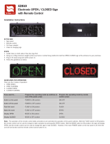
Mounting
The SHD45 is designed for installation in panels from 0.032 to 0.125 in.
(1 to 3 mm) thick. A round hole, 4-3/4 in. (121 mm) in diameter is need-
ed for mounting. Install the unit within a weatherproof enclosure to pro-
tect it from the elements. Keep the unit away from ignition coils and coil
leads; a minimum of 12 in. (305 mm) is recommended.
Please read the following information before installing. A visual inspection for any damage which may have occurred during shipping is recommended.
It is your responsibility to have a qualified person install the unit, and make sure it conforms with NEC and local codes.
GENERAL INFORMATION
1/4 in.
(6 mm)
dia.
3 holes
120
120
120
2-39/64 in.
(66 mm)
radius
Mounting Hole
4-3/4 in.
(121 mm)
diameter
Mounting
Screws
panel
Tachometer
4-11/16 in.
(119 mm)
3-3/16 in.
(81 mm)
5-27/64 in.
(138 mm)
WARNING
BEFORE BEGINNING INSTALLATION OF THIS MURPHY PRODUCT
✔ Disconnect all electrical power to the machine.
✔ Make sure the machine cannot operate during installation.
✔ Follow all safety warnings of the machine manufacturer.
✔ Read and follow all installation instructions.
SHD45 Dimensions
Mounting Hole
Made in USA
®
FRANK W.
MFR.
SHD45
PULSES
PER
REVOLUTION
RESET RELAY
READ HOURS
OVERSPEED
SETPOINT
DOWN
UP
Approved for Class I, Division 2,
Groups C & D Hazardous Areas
NRTL/C*
*When installed per Murphy Drawing 20-08-0255 Revision C.
Call Murphy for Details.

SHD-96113N page 2 of 4
TYPICAL WIRING
Connecting the Magnetic Pickup
Connect the magnetic pickup cable conductors to the 6 connector ter-
minal strip as shown in Figure 2. Use a two conductor shielded cable
between the SHD45 and the magnetic pickup.
Connecting to CD Ignition
Before wiring the SHD45, determine the output voltage and ground
polarity of the ignition. Table 1 (below, left) lists the Peak Output
Voltage and Ground Polarity of some common ignitions.
Connect the SHD45 to a positive or a negative ground CD ignition as
shown in Figures 3 or 4.
RESET
MPU
Magnetic Pickup
2 Conductor
Shielded Cable
Flywheel
Back of
SHD45
Figure 2:
SHD45 to magnetic pickup typical wiring
1
2
+
–
3
4
1
CD Ignition
90-350 VDC
GND
2
3
4
5
6
+
--
IGN
1
2
+
–
3
4
1
CD Ignition
90-350 VDC
GND
2
3
4
5
6
+
--
IGN
Figure 3:
SHD45 typical wiring for NEGATIVE ground ignition
Figure 4:
SHD45 typical wiring for POSITIVE
ground ignition
Ignition
MFG & Series
Ground
Polarity
Peak Output
Voltage
Use Figure
Altronic III Negative 225 3
Altronic II Positive 350 4
Bendix S-1800, BLAR Negative 250 3
Bendix Side-winder Positive 300 4
Fairbanks Morse SCSA Positive 180 4
Fairbanks Morse
3000 & 9000
Negative 225 3
American Bosch Magtronic
Negative 165
Altronic I & V Negative 120 3
3
Table 1:
Output Voltage & Polarity of Common CD Ignitions
WARNING
:
PERFORM THE WIRING INSTALLATION WITH THE POWER SOURCE OFF.
NEVER ROUTE THE SHD45 OVERSPEED OUTPUT LEADS WITH PRIMARY IGNITION WIRING.
16
17
32
Remove
Jumper
Back of MARK III
1
2
+
–
3
4
1
CD Ignition
90-350 VDC
GND
2
3
4
5
6
+
--
IGN
16
17
32
Leave Jumper
in place
Back of MARK
III
1
2
+
–
3
4
1
CD Ignition
90-350 VDC
GND
2
3
4
5
6
+
--
IGN
OVERSPEED OUTPUT WIRING
Connecting the Overspeed Output
A 4-connector terminal strip, on the back of the SHD45, is provided for
connection of the overspeed output. Terminals 1 and 2 are used for
connecting the output as a normally closed relay contact. Terminals 3
and 4 are used for connecting the output as a normally open SCR out-
put. Shown in Figure 5 is a typical wiring installation of the SHD45
normally closed relay output
connected to a Murphy MARK III digital
fault annunciator. Shown in Figure 6 is a typical wiring of the SHD45
normally open SCR output
connected to a Murphy MARK III digital
fault annunciator.
Figure 7 displays a typical wiring of the SHD45 nor-
mally open SCR output to a Murphy MARK II annunciator. Figure 8 dis-
plays a typical wiring of the SHD45 normally open SCR output to a
Murphy MARK IV annunciator. Figure 9 displays a typical wiring of the
SHD45 normally closed relay output to a Murphy LCDT-NC annunciator.
Figure 10 displays a typical wiring of the SHD45 normally open SCR over-
speed output to a Murphy LCDT-NO annunciator.
Figure 5:
SHD45 Normally Closed Relay output to MARK III
To be installed in accordance with NEC
code for Cl. I, Div. 2 Grps. C & D
hazardous locations.
To be installed in accordance with NEC code for
Cl. I, Div. 2 Grps. C & D hazardous locations.
Figure 6:
SHD45 Normally Open SCR output to MARK III
WARNING: Overspeed relay contact for
use with Frank W. Murphy Mfr. non-incen-
dive or intrinsically safe products only.

SHD-96113N page 3 of 4
WARNING
:
PERFORM THE WIRING INSTALLATION WITH THE POWER SOURCE OFF.
NEVER ROUTE THE SHD45 OVERSPEED OUTPUT LEADS WITH PRIMARY IGNITION WIRING.
44
50
44
45
45
46
46
47
47
48
1
2
+
–
3
4
1
CD Ignition
90-350 VDC
GND
2
3
4
5
6
48
49
49
50
LCDT
Terminal Block
+
--
IGN
14
Back of MARK
II
1
2
+
–
3
4
1
CD Ignition
90-350 VDC
GND
2
3
4
5
6
+
--
IGN
46
Back of MARK IV
1
2
+
–
3
4
1
CD Ignition
90-350 VDC
GND
2
3
4
5
6
+
--
IGN
46
LCDT
Terminal Block
50
1
2
+
–
3
4
1
CD Ignition
90-350 VDC
GND
2
3
4
5
6
+
--
IGN
OVERSPEED OUTPUT WIRING continued
Figure 9:
SHD45 Normally Closed Relay output to LCDT-NC
Figure 7:
SHD45 Normally Open SCR output to MARK II
Figure 8:
SHD45 Normally Open SCR output to MARK IV
Figure 10:
SHD45 Normally Open S.C.R. output to LCDT-NO
To be installed in accordance with NEC code for Cl. I,
Div. 2 Grps. C & D hazardous locations.
To be installed in accordance with NEC code for Cl. I,
Div. 2 Grps. C & D hazardous locations.
To be installed in
accordance with
NEC code for Cl. I,
Div. 2 Grps. C & D
hazardous locations.
To be installed in accordance with NEC code for Cl. I,
Div. 2 Grps. C & D hazardous locations.
1G23
SW
ALT 2
ALT 1
GRD
Pressure Overspeed Level
1 23
1 23456
65-02-0155
Adapter
Package
Emergency
Stop Switch
Frame Ground
307PHCD
TATTLETALE
®
Connect to
Good Engine
Ground
CD Ignition
90-350 VDC
+–
SWICHGAGE
®
RESET
POS
OS
NC
OS
+
NO
–
NEG
CD IGN
MPU
1G23
SW
ALT 2
ALT 1
GRD
Pressure Overspeed Level
1 23
1 23456
65-02-0127
Adapter
Package
Emergency
Stop Switch
Frame Ground
307PHCD
TATTLETALE
®
Connect to
Good Engine
Ground
CD Ignition
90-350 VDC
+–
SWICHGAGE
®
RESE
T
POS
O
S
N
C
OS
+
NO
–
NEG
C
D IGN
MPU
Figure 11:
SHD45 with Normally Open S.C.R. output typical
wiring for negative ground ignition systems.
Figure 12:
SHD45 with Normally Open S.C.R. output typical
wiring for positive ground ignition systems.
Shown below is the SHD45 with SCR output connected to TATTLE-
TALE
®
magnetic switches and SWICHGAGE
®
instruments using an
adapter package. Figure 11 shows a typical wiring for negative ground
ignition. Figure 12 shows a typical wiring for positive ground ignition.
TYPICAL WIRING FOR CONTROL PANEL
To be installed in accordance with NEC code for Cl. I,
Div. 2 Grps. C & D hazardous locations.
To be installed in accordance with NEC code for Cl. I,
Div. 2 Grps. C & D hazardous locations.
WARNING: Overspeed relay contact for
use with Frank W. Murphy Mfr. non-incen-
dive or intrinsically safe products only.

SHD-96113N page 4 of 4
Resetting the Run Hours
To reset the Run hours to zero, place a jumper between terminals (terminals #3 and
#4 of the 6-point terminals). Press and hold the Reset Relay Read Hours key on the
SHD45 faceplate for 5 seconds. The Run Hours will be reset to zero.
Presetting the Run Hours
To preset the run hours first you must reset the run hours (see the above para-
graph). After resetting the hours continue to hold the Reset Relay Read Hours
key for another 5 seconds. The run hours will flash 3 times. At this point the
hours can be preset in hours using the up/down keys to increase or decrease the
hours. When the desired preset run hours is reached, continue holding the Reset
Relay Read Hours
key for another 5 seconds. The run hours must flash 3 times
indicating the run hours value has been saved.
Pulses Per Revolution Adjustments
The SHD45 measures RPM based on the number of pulses per engine revolution.
Pulses can come from either an ignition or a magnetic pickup. For an ignition, the
number of pulses per revolution is determined by the number of cylinders and
cycles, refer to Table 2.
For magnetic pickup, the number of pulses per revolution is simply the number of
teeth on the gear. To adjust the pulses per revolution do the following:
1.
Press and hold the Reset Relay Read Hours key. Run hours will be displayed.
Continue to hold the Reset
Relay Read Hours key.
2.
Press the DOWN
key and hold for 5 seconds. The current pulses per revolution
value will flash indicating that it now can be changed.
3.
Continue to hold the Reset Relay Read Hours key. Use the the UP/DOWN
keys to increase and decrease the number of pulses per revolution. Once the
desired value is displayed, continue holding Reset
Relay Read
Hours key for
5 seconds, the display must flash 3 times indicating that the new value is
saved (the display MUST flash 3 times for the new value to be saved).
Overspeed Set Point Adjustments
To adjust the overspeed set point perform the following steps:
1.
Press and hold the Reset Relay Read Hours key. Run hours will be displayed.
Continue to hold the Reset Relay Read Hours key.
2.
Press the UP key and hold for 5 seconds. The current overspeed set point value
will flash indicating that it now can be changed.
3.
Continue to hold the Reset Relay Read Hours key. Use the UP/DOWN keys to
increase and decrease the number of overspeed set point. Once the desired value is
displayed, continue holding the Reset Relay
Read Hours key for 5 seconds, the
display will flash 3 times indicating that the new value is saved (the display
MUST flash 3 times for the new value to be saved).
Operation Sequence
When the SHD45 receives a tach signal, it begins displaying RPM. When the
RPM reading is flashing, it means that the overspeed setting has been tripped
(see Overspeed Output Tripped, below).
Run Hours Display
To display the run hours, press Reset
Relay Read Hours key. The run hours will
be displayed for 5 seconds before returning to RPM.
To configure the SHD45 to automatically toggle between displaying rpm and run
hours, press the Reset
Relay Read Hours key twice quickly. The display will tog-
gle between displaying rpm for 6 seconds, and run hours for 2 seconds. The setting
is saved and does not have to be performed every time the unit is powered up. Press
the Reset Relay Read Hours key twice again to return to displaying rpm only.
Overspeed Set Point Display
To display the overspeed set point, press the UP key. The current overspeed set
point will be displayed for 5 seconds before returning to RPM.
Overspeed Output Tripped
When RPM exceeds the overspeed setting, the normally open SCR output trips
and latches, and the normally closed relay output opens. To reset the relay output,
press Reset Relay Read Hours key after RPM has fallen below overspeed set
point. The current through the SCR must be broken to allow the SCR to reset in
addition to pressing Reset
Relay Read
Hours key.
Pulses Per Revolution Display
To display the pulses per revolution, press the DOWN
key. Current pulses per rev-
olution will be displayed for 5 seconds before returning to RPM.
Replacing the Backup Batteries
Backup batteries are provided to allow display of the run hours and for resetting the
overspeed relay after power is lost. To replace the batteries, first remove the SHD45
from the panel. Remove the 3 screws located on the back of the SHD45 and VERY
CAREFULLY remove the face plate. The 2 on-board batteries are above the circuit
board. Replace existing batteries with new ones observing polarity (batteries are
available from a Murphy dealer). Replace the face plate and the screws.
Remount the SHD45 on panel.
CALIBRATING AND OPERATING THE SHD45
Cylinders Cycles Pulses
121
222
241
323
424
442
525
Cylinders Cycles Pulses
626
643
828
844
10 4 5
12 4 6
16 4 8
Table 2:
Cylinders, Cycles, Pulses Per Revolution
NOTE: Divide the number of cylinders by 2 for split capacitor ignitions.
Multiply the number of cylinders by 2 for throw away spark ignitions.
Warranty
A two year limited warranty on materials and workmanship is provided with this Murphy product.
Details are available on request and are packed with each unit.
CONTROL SYSTEMS & SERVICES DIVISION
P.O. Box 1819; Rosenberg, Texas 77471; USA
(281) 342-0297 fax (281) 341-6006
e-mail [email protected]
MURPHY DE MEXICO, S.A. DE C.V.
Blvd. Antonio Rocha Cordero 300, Fracción del Aguaje
San Luis Potosí, S.L.P.; México 78384
+52-444-8206264 fax +52-444-8206336
e-mail [email protected]
www.murphymex.com.mx
FRANK W. MURPHY, LTD.
Church Rd.; Laverstock, Salisbury SP1 1QZ; U.K.
+44 1722 410055 fax +44 1722 410088
e-mail [email protected]
www.fwmurphy.co.uk
MURPHY SWITCH OF CALIFORNIA
41343 12th Street West
Palmdale, California 93551-1442; USA
(661) 272-4700 fax (661) 947-7570
e-mail [email protected]
www.murphyswitch.com
In order to consistently bring you the highest quality, full featured products, we reserve the right to change our specifications and designs at any time.
MACQUARRIE CORPORATION
1620 Hume Highway
Campbellfield, Vic 3061; Australia
+61 3 9358-5555 fax +61 3 9358-5558
e-mail [email protected]
FWMurphy
P.O. Box 470248
Tulsa, Oklahoma 74147 USA
(918) 317-4100
fax (918) 317-4266
e-mail [email protected]
www.fwmurphy.com
R
E
G
I
S
T
E
R
E
D
Printed in U.S.A.
/