Page is loading ...

USER’S MANUAL
Dry Vacuum System
Part Numbers: V15, 2V15, 3V15 and 4V15
Recommend Daily
use of
Monarch
CleanStream

2
Description Page
Congratulations ......................................................3
Purpose of this Manual.................................................3
Safety Summary ......................................................4
Specifications........................................................5
Product Description ...................................................6
Installation Information.................................................9
MOJAVE System Configurations ..........................................13
Installation..........................................................14
Electrical Connections .................................................26
Operating Information .................................................27
Operation ..........................................................31
Troubleshooting ......................................................32
Maintenance ........................................................34
Accessories/Options...................................................36
Warranty ...........................................................37
Online Warranty Registration ............................................37
LIST OF ILLUSTRATIONS
Figure Description Page
1 Main System Components . . . . . . . . . . . . . . . . . . . . . . . . .7
2 Typical MOJAVE Functional Flow Diagram . . . . . . . . . . . . . . . . .8
3 MOJAVE System Component Dimensions . . . . . . . . . . . . . . . . . 10
4 V15, 2V15, 3V15 and 4V15 System Floor Plan . . . . . . . . . . . . . . 12
5 MOJAVE System Configuration Layouts . . . . . . . . . . . . . . . . . . 13
6 Stacking Two MOJAVE Pumps Hardware Detail . . . . . . . . . . . . . . 14
7 CT12 and CT34 Check Valve and Gate Valve Operating Position . . . . . 14
8 Master Controller Assembly and Washout Solenoid Optional Mounting . . 14
9 MOJAVE V15 Pump and CT12 Tank Connection Diagram. . . . . . . . . 16
10 MOJAVE V15 Pump Vent and CT12 Tank Drain Connection Diagram . . . 18
11 MOJAVE Dual Pump and CT12 Tank Connection Diagram . . . . . . . . 20
12 MOJAVE Dual Pump Vent and CT12 Tank Drain Connection Diagram . . . 21
13 CT12 and CT34 Tank Output, Drain and Pump Vent Connection Diagram . 24
14 CT12 Tank to CT34 Tank and Washout Port Connections Diagram . . . . 25
15 MOJAVE Pump Power Connection . . . . . . . . . . . . . . . . . . . . 26
16 Master Controller Wiring Diagram . . . . . . . . . . . . . . . . . . . . 26
17 Master Controller Assembly Controls and Indicators . . . . . . . . . . . . 28
18 Monarch CleanStream Dispenser Cap Adaptor Locations . . . . . . . . . 36
TABLE OF CONTENTS

3
LIST OF TABLES
Table Title Page
1 MOJAVE Accessory Packs and System Installation Kits . . . . . . . . . . . .9
2 V15 Pump Accessory Pack, P/N H5403 . . . . . . . . . . . . . . . . . . 15
3 CT12 Tank Accessory Pack, P/N H5489 . . . . . . . . . . . . . . . . . 15
4 V15 Tank Outlet Kit, H5501 . . . . . . . . . . . . . . . . . . . . . . . 15
5 2V15 Tank Outlet Kit, H5502 . . . . . . . . . . . . . . . . . . . . . . 19
6 Quantity of Accessory Packs and Kits Used on 3V15 and 4V15 . . . . . . 22
7 CT34 Tank Accessory Pack, P/N H5288 . . . . . . . . . . . . . . . . . 22
8 Master Controller Controls and Indicators . . . . . . . . . . . . . . . . 29
9 Master Controller Assembly Menu Display Mode . . . . . . . . . . . . . 30
10 Master Controller Assembly Error Reporting . . . . . . . . . . . . . . . . 32
11 Troubleshooting . . . . . . . . . . . . . . . . . . . . . . . . . . . . . 33
Congratulations on the purchase of your new MOJAVE Dry Vacuum System that provides the
state of the art in vacuum technology. This vacuum system is designed for reliable operation in
the modern dental facility. The system uses a 100% oil-less Vacuum Pump to produce the high-
volume air flow required for multiple simultaneous users while the Separator Tank ensures that no
liquids enter the pump.
In addition, MOJAVE incorporates an efficient energy management system. This is accomplished
by adding a Variable Frequency Drive (VFD) to the Vacuum Pump, which is controlled by a Master
Controller. This controller automatically adjusts the frequency of the pump to maintain the required
vacuum level depending on the needs of your dental facility. With this balanced system, each user
always has the flow rate necessary to do the job while conserving electricity and prolonging the life
of your pumps.
This manual provides installation, operation and maintenance instructions for the support of the four
available MOJAVE Dry Vacuum System configurations listed below. Although not listed, each system
also includes a Master Controller. Review and follow the guidelines included in this User Manual to
ensure that the system provides the highest level of service.
System Description Maximum
Users
V15 One V15 Dry Vacuum Pump and one CT12 Tank 15
2V15 Two V15 Dry Vacuum Pumps and one CT12 Tank 30
3V15 Three V15 Dry Vacuum Pumps with CT12 and CT34 Tanks 45
4V15 Four V15 Dry Vacuum Pumps with CT12 and CT34 Tanks 60
CONGRATULATIONS
PURPOSE OF THIS MANUAL

4
4
Use of MOJAVE not in conformance with the instructions specified in this manual may result in
permanent failure of the unit.
WARNING: To prevent fire or electrical shock, do not expose this appliance
to rain or moisture.
All user serviceable items are described in the maintenance section.
ATTENTION USERS:
Markings. The following terms or symbols are used on the equipment or in this manual to
denote information of special importance:
Alerts users to important Operating
and Maintenance instructions. Read
carefully to avoid any problems.
Warns users that uninsulated voltage
within the unit may be of sufficient
magnitude to cause electric shock.
Indicates the ON and OFF position for
the Equipment power switch.
I ON
O OFF
Indicates protective Earth Ground for the
Equipment power switch.
Warns users of hot surfaces. There is a danger
of burns. Work near these surfaces only after
they have cooled down.
MEDICAL ELECTRICAL EQUIPMENT
WITH RESPECT TO ELECTRICAL SHOCK, FIRE, MECHANICAL
AND OTHER SPECIFIED HAZARDS ONLY
IN ACCORDANCE WITH UL 60601-1, CAN/CSA C22.2 No. 601.1
66CA
C
L
A
S
S
I
F
I
E
D
Indicates date of manufacture
Identifies the name of the
manufacturer.
SAFETY SUMMARY
Air Techniques, Inc.
1295 Walt Whitman Road
Melville, New York, USA 11747- 3062

5
Master Controller Electrical Specifications
Voltage (Volts AC Single Phase ± 10%) 220
Full Load Current (Amps AC) 5
Input Frequency (Hz) 50/60
Pump Electrical Specifications V15 2V15 3V15 4V15
Voltage (Volts AC, 3 Phase, ± 10%)220 220 220 220
Full Load Current (Amps AC) 25 50 75 100
Input Frequency (Hz) 50/60 50/60 50/60 50/60
Preset Vacuum Level (InHg) 10 10 10 10
Horsepower (each V15 pump) 4.6 kW or 6.2 HP
Tank Specifications V15 & 2V15 3V15 & 4V15
Working Liquid Capacity CT12 Continuum Tank
infinite volume capacity
CT12 and CT34 Continuum
Tanks infinite volume capacity
Tank Material Rotomolded Plastic Rotomolded Plastic
Water usage in Gallons Per Minute (GPM) at different facility water pressures.
Water Pressure (PSI) Gallons Per Minute (GPM)
for CT12
Gallons Per Minute (GPM)
for CT12 and CT34
20 7.4 14.8
30 9.0 18.0
40 10.4 20.8
50 11.6 23.2
60 12.7 25.4
80 14.7 29.4
100 16.4 32.4
System Environmental Conditions (All Systems)
Operating Temperature 40 to 104°F or 10 to 40°C
Storage and Transport Temperature 32 to 158°F or 0 to 70°C
Operating Relative Humidity 80%, no condensation
Storage and Transport Relative Humidity 90%, no condensation
UL60601-1 CLASSIFICATION
Protection against electrical shock (5.1, 5.2) Class I, Transportable, Continuous Operation. No applied parts.
Protection against ingress of liquids-Ordinary Equipment not suitable for use in the presence of flammable anaes-
thetic mixture with air or with oxygen or nitrous oxide.
All MOJAVE vacuum pumps comply with NFPA 99C level 3 requirements.
SPECIFICATIONS

6
As shown by Figure 1, the MOJAVE Dry Vacuum System consists of the major components listed below.
Vacuum Pump Assembly V15.
A dual-stage pump, where all of the wetted metal parts are aluminum or stainless steel.
A metal electrical enclosure that houses a Variable Frequency Drive (VFD), circuit breaker,
axial fan and an interface Printed Circuit Board (PCB).
A metal chassis for mounting components.
Continuum Separation Tank Assemblies CT12 AND CT34.
Each continuum tank combines two molded plastic tanks connected via a check valve and
two solenoid valves. A third solenoid is used for the washout cycle. This tank is capable
of handling an infinite volume of liquid because one tank section drains as the other tank
section fills, while maintaining a preset vacuum level.
Each tank has an internal float switch that signals the Master Controller to toggle the state
of the tank and air solenoid.
Solenoids keep the liquid moving through the tanks by controlling the venting and pressur-
ization of each tank.
Each tank has a washout port with internal nozzle that is used to rinse the interior of the tank
during the automatic Washout Cycle.
A metal chassis for mounting components.
Master Controller. This self-contained metal enclosure is mounted on the front of the CT12 tank
chassis. The unit includes a Main PCB, Front Panel PCB and an LCD Display PCB to provide the
following system functions:
Retains the operational user interface for the MOJAVE system.
Monitors as well as displays the frequency, vacuum level and temperature.
Records the run time of up to 4 connected pumps in hours.
Balances the vacuum load equally across all running pumps.
Displays any error/fault codes.
Controls the Washout function.
PRODUCT DESCRIPTION

7
Figure 1. Main System Components
V15 Vacuum Pumps
CT12 & CT34 Tank Rear View
Tank & Air
Solenoids
Master Controller
Primary CT12 Tank Front View
Dual Tank
Outlet to
Pumps
Tank Inlet
from
Operatory
Master
Controller
Leveling
Feet
Tank Drain
Check
Valve Gate
Valve
Washout
Port
Washout
Solenoid Bottom Float
Switch
Top Tank
Vent Fitting
Bottom
Tank
Vent
Fitting
Junction
Box
Secondary CT34 Tank (No MMC)
Air Inlet Port
with Filter
Leveling
Feet
Junction
Box
Vacuum Inlet
Port
Panel Knockouts
for CAT 5 Cable
(10-feet) to Pumps
Circuit Breakers
Door Retainer 1/4
Turn Screws
AC Power IEC Receptacle
Front Panel Controls
and Indicators
24 VAC Output
Air Solenoid
Low Voltage Control
Panel Switch and
Float Switches
Washout Solenoid
(Note: The 10-foot Line Cord is the
Mains disconnect device for
the Master Controller.)
Tank Solenoid
Vacuum
Pump
Electrical
Box
Circuit
Breaker
Axial Fan
Exhaust
Port
Electrical
Box
Rear View
Front View
PRODUCT DESCRIPTION
Washout
Port
Top Float
Switch

8
Figure 2. Typical MOJAVE Functional Flow Diagram
Vacuum System Operation.
Air, water, and solids from the operatory are pulled into the separator tank. See Figure 2. Air is expelled
out through the pump exhaust while liquids and solids fall to the bottom of the tank. The vacuum in
the tank keeps the check valve to the drain closed while the tank gradually fills.
Each continuum tank (CT12 and CT34) has two internal float switches and two 2-way solenoids. The float
switches control the state of the two solenoids to allow the filling and draining of each tank, keeping the
liquid moving through each tank. When the top tank is filling, the bottom tank is draining and when a
bottom tank is filling, the top tank is draining. The preset vacuum level is maintained in either state. If
the top float switch is active, the Master Controller stops the operation of all connected pumps. Once
the tank drains, the Master Controller automatically restarts the primary pump.
When an instrument (suction tip) has been opened, the Master Controller senses an increase in vacuum
demand and will instruct the VFD to speed up the motor.
Conversely, when an instrument (suction tip) has been closed, the Master Controller will instruct the VFD
to slow motor operation down due to decreased vacuum demand. The Master Controller can also turn
on and off up to 4 connected pumps to regulate the vacuum level.
Additionally, the Master Controller initiates a 2-minute tank washout cycle when the system has been in
Standby for 5 minutes.
Any time the power to the MOJAVE is turned
OFF the tanks will automatically drain.
PRODUCT DESCRIPTION
Gas/Liquids/
Solids
From
Treatment
Room
Exhaust to
Outside Vent
V15
Vacuum
Pump
Gate
Valve
Sewer
Drain
CT12 Tank
Gas
Check
Valve
Air Inlet Port
Filter
Liquids/Solids

9
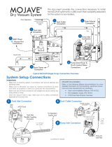
General. For new installations it is recommended to follow the following guidelines:
Make sure to install the system in accordance with all local electrical and plumbing codes.
Sizes of each suction line from the operatories differ between MOJAVE systems. See Site
Requirements provided on page 11.
The suction line should not have any sharp right angle bends and must be sloped a minimum
of ¼ inch for every 10 feet toward the separation tank.
The drain on the base of the separation tank must be connected to a vented or an open floor
drain capable of handling 10 gallons in 30 seconds. Drain pipe size 1 ½ inch schedule 40.
The drain line should be a short run with a minimum slope of ¼ inch for every 10 feet toward
the drain (avoid any sharp right angle bends).
Vent line requirements differ among MOJAVE systems. See Site Requirements provided on
page 11.
Make sure to install the supplied drip leg assembly to the bottom end of the facility vent line.
The vent should be sloped ¼ inch per 10 feet towards the pump. Vent lines must be capable
of handling vapors and liquids.
The outside vent must be protected from rain and animals.
A flexible air exhaust hose is provided to connect to the 2 inch diameter vent pipe and exhaust
port of the pump. Hose clamps are provided to secure hose to each exhaust port and pipe.
Wash-out water supplied via ½ inch copper tubing terminated with a ½ inch FNPT shut-off
valve providing water pressure between 20 and 100 psi.
Wash-out port on the tank top is a 3∕8 inch push to connect elbow that connects to the water
supply via supplied 10 foot 3∕8 inch Poly tubing and ½ MNPT x 3∕8 inch push to connect adapter.
As shown by Figure 1, the Master Controller is delivered mounted on the front chassis of the
fully assembled CT12 tank associated with the system. In addition to the water connection
at the washout solenoid, electrical and vacuum connections must also be made.
Accessory packs and system installation kits shipped with associated MOJAVE systems are
listed below. Refer to the Installation Section for a listing of components supplied with each
kit and the instructions necessary to install specific MOJAVE systems.
Grounding reliability can only be achieved when the Master
Controller is connected to a HOSPITAL GRADE receptacle.
Table 1. MOJAVE Accessory Packs and System Installation Kits
Part No. Description Included With Every
H5403 MOJAVE V15 Pump Accessory Pack V15 Pump
H5501 V15 Tank Outlet Kit V15 and 3V15 System
H5502 2V15 Tank Outlet Kit 2V15, 3V15 and 4V15 System
H5489 CT12 Tank Accessory Pack CT12 Tank
H5288 CT34 Tank Accessory Pack CT34 Tank
INSTALLATION INFORMATION

10
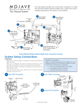
Figure 3. MOJAVE System Component Dimensions
Physical Characteristics
Master
Controller
CT12 & CT34
Continuum Tank
One
V15 Pump
Two V15 Pumps
Stacked
Width 11 in. (28 cm) 25 in. (64 cm) 32.5 in. (83 cm) 32.5 in. (83 cm)
Depth 3 in. (8 cm) 23 in. (58 cm) 26 in. (66 cm) 26 in. (66 cm)
Height 10 in. (24 cm) 42 in. (107 cm) 23.5 in. (60 cm) 47 in. (119 cm)
Weight 13 Lbs. (6 kg) 175 Lbs. (65 kg) 250 Lbs (93 kg) 500 Lbs (187 kg)
Master Controller Dimensions
10 in.
(24 cm)
11 in. (28 cm)
11 in.
(28 cm)
13.5 in. (34 cm) 3 in.
(8 cm)
V15 Vacuum Pump Dimensions
32.5 in. (83 cm)
23.5 in.
(60 cm)
26 in. (66 cm)
CT12 and CT34 Continuum Tank Dimensions
23 in.
(58 cm)
52 in.
(132 cm)
23 in.
(58 cm)
25 in.
(64 cm)
42 in.
(107 cm)
INSTALLATION INFORMATION

11
Plumbing V15 2V15 3V15 4V15
Exhaust Vent Pipe
(See note 1) 2” Metal Pipe One 3” or two
2” Metal Pipe
One 4” or three 2”
Metal Pipe
Two 3” or four
2” Metal Pipe
Minimum Suction Line Pipe 2” PVC Sch. 40 3” PVC
Sch. 40
3” PVC
Sch. 40
4” PVC
Sch. 40
Maximum Suction Line Pipe
(See note 2)
3” PVC
Sch. 40
4” PVC
Sch. 40
4” PVC
Sch. 40
6” PVC
Sch. 40
Riser Pipe ½” PVC Sch. 40 ½” PVC
Sch. 40
½” PVC
Sch. 40
½” PVC
Sch. 40
Vacuum Line Termination 2” 2” 2” 2”
Branch Line Pipe Size requirement of branch piping diers by the number of operatories being serviced.
Up to two operatories use 1" PVC Schedule 40.
Three to six operatories use 1 ½” PVC Schedule 40.
More that six operatories use 2" PVC Schedule 40
Drain Line Pipe 1 ½” PVC Schedule 40
Wash-Out Water Line ½” FNPT Shut-off Valve
Site Requirements
Electrical V15 2V15 3V15 4V15 Master
Controller
Voltage Rating Volts AC All pumps 220 Volts 3 Phase AC, 60 Hz, ± 10% 220
(Single Phase ± 10%)
Voltage Minimum/
Maximum 198/242 Volts AC All pumps 198/242
Wire Size AWG Minimum
Gauge #8 AWG #8 AWG #8 AWG #8 AWG #14 AWG
Minimum Circuit Breaker
Rating 40A 40A (Qty 2) 40A (Qty 3) 40A (Qty 4) 15A
Incoming Power Hard wire Connection
(Each pump is supplied a 6 foot BX cable)
NEMA 6-15R
(Supplied 10-ft. line cord)
Remote 24V
(Low Voltage Wiring)
#18 AWG (Qty 4) Wire Connection between the MMC and the Remote Switch Panel .
(See Figure 16, page 26.)
NOTES
1. Recommend use wrought iron pipe (black or galvanized) or copper pipe type M.
2. Use maximum internal diameter for the main line when preparing any new installation.
INSTALLATION INFORMATION

12
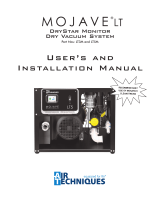
Figure 4. V15, 2V15, 3V15 and 4V15 System Floor Plan
48"
4"
4"
150"
20"
Sewer Drain
12"
4"
4"
24"
Secondary
CT34 Tank
(no MMC)
30"
Single or
Stacked V15
Pumps
64"
84"
1" 12" 24"
4"
Primary
CT12 Tank
(with MMC)
Single or
Stacked V15
Pumps
30"
36"
C
BAA
D
E
G
F
H
J
Installation Notes.
Installation Layout Space. Figure 4 shows the requirements for the installation of the various
MOJAVE model configurations. Please note that all tanks are shipped with leveling feet set to lowest
position. Heights can be increased by 1 inch by adjusting the leveling feet. The pump assembly is
shipped without the leveling feet installed. They are supplied in the V15 Pump Accessory Kit, H5403.
Refer to Figure 5 for the recommended configuration arrangements.
A. PUMP INSTALLATION SPACE - Area for single or stacked V15 pumps in typical side by side installations. Only stack
up to 2 pumps in one area.
B. TANK INSTALLATION SPACE - Area for CT12 or CT34 tank in typical side by side installations.
C. SEWER DRAIN - Provide a drain for the removal of waste liquids from the MOJAVE tank. Use an open drain pipe (1 ½
inch P-Trap with 1 inch air gap or floor sink) or a closed vented drain.
D. TANK WASHOUT - Provide a water source terminated with a ½ inch FNPT shut-off valve providing water pressure
between 20 and 100 psi for daily tank washout. Valve location must be no more than 10 feet from the tank installation
to allow connection of supplied 10-foot 3/8-inch Poly tubing to the tank washout port. Provisions for backflow prevention
may be required. Check local code requirements.
E. SUB FLOOR INSTALLATION VACUUM LINE - See Plumbing Requirements for connection to tank inlet via supplied hose.
F. MASTER CONTROLLER ELECTRIC OUTLET - Master Controller requires a dedicated standalone 220V, hospital grade
grounded receptacle. The supplied 10-foot line cord is the Mains disconnect device for the unit.
G. PUMP ELECTRIC SERVICE - Each MOJAVE pump is wired directly with a dedicated 220V, 40 AMP, three phase 50/60 Hz
circuit. If the main circuit panel is not located in equipment room, a disconnect box with approved ground is needed for
each pump. Disconnect boxes should be mounted no more than 3 feet of each other and 3 feet of installation center line.
H. OVERHEAD INSTALLATION VACUUM LINE - See Plumbing Requirements for connection to tank inlet via supplied hose.
J. HEAT EXHAUST - See Plumbing Requirements for the exhaust vent line required for specific MOJAVE configurations. Schedule
40 pipe can normally be used on typical MOJAVE configuration installations. When installing two pumps, a reducing Y adapter
(See Figure 10.) is needed to connect both vent tubes to a common 3-inch exhaust vent line.
B
INSTALLATION INFORMATION

3V15 System Installation
Three V15 Pumps (2 stacked) with CT12 and CT34 Tanks on the Side
4V15 System Installation
Two Side by Side Stacks of Two V15 Pumps with CT12 and CT34 Tanks on the Side
Important: Side by side installation of pump and tank is preferred.
V15 pumps should only be stacked two high in all other system configurations as shown.
All tanks are shipped with leveling feet set to lowest position.
V15 pumps are shipped without leveling feet. They are supplied in pump accessary kit.
V15 System Installation: One V15 Pump and
One CT12 Tank Installed Side by Side
Figure 5. MOJAVE System Configuration Layouts
MOJAVE SYSTEM CONFIGURATIONS
2V15 System Installation: Two V15 Pumps
Stacked with One CT12 Tank on the Side
Stacked V15 System
Installation: One CT12 Tank
above One V15 Pump (See note.)
Note: Stacked V15 System is only configuration that allows a CT12 Tank
to be stacked above a V15 Pump. Use Drip Shield Kit, H5454
13

14
INSTALLATION
Figure 6. Stacking Two MOJAVE Pumps Hardware Detail
TWO
V15
PUMPS
1/4-20 X
1/2" HEX Bolt
(Quantity 4)
1/4" Lock Washer
(Quantity 4)
Note: See MOJAVE V15 Pump Accessory Pack, P/N H5403, for
required fastener hardware.
Do Not install leveling feet on top pump to be stacked.
1/4" Flat Washer
(Quantity 4)
Figure 8. Washout Solenoid Optional Mounting
Mounting
Keyholes
5-Foot Flexible
Cable Washout Solenoid
will be Pre-Wiried to
the junction box.
Flow Direction OUT
IN
Washout Solenoid
Washout Solenoid Installation Options. The Washout Solenoid is delivered installed on the rear of
CT12 and CT34 tanks.
Although not recommended, the Washout Solenoid can be installed on the equipment room wall.
The solenoid should be located between the facility water supply and the Master Controller. Securing
hardware consisting of Plastic Screw Anchors, P/N 30936 and Plated Slot Pan Head Screws, P/N
30295 are provided by the CT12 Tank Accessory Pack, P/N H5489.
Important - Check Valve:
For proper operation, the Check Valve
must be installed with the ow arrow
positioned on top and pointing towards
the inlet port of the bottom tank.
Important - Gate Valve:
For proper operation, make sure that the
Gate Valve of the Tank Drain is set in the
open position.
Closing the Gate Valve will stop all drainage
from the tank.
Tank Drain
Gate Valve
Figure 7. CT12 and CT34 Check Valve and Gate Valve Operating Position

15
V15 System Installation.
Note: Each kit provides the required hoses, coupling clamps and adapters.
No schedule 40 PVC pipe is included.
Installation Accessory Packs. Figures 9 and 10 show the hose connections required for the V15
MOJAVE System configuration installations using accessory packs that provide the required hoses,
coupling clamps and adapters as follows:
V15 Pump Accessory Pack, P/N H5403 - supplied with each pump and is used to connect
the pump exhaust to the facility vent line, connection item (3) on Figure 10.
CT12 Tank Accessory Pack, P/N H5489 - used to make the following connections:
• Between the suction line and tank inlet. Item (1) on Figure 9.
• Install an exhaust vent assembly to the facility vent line, connection item (4) on Figure 10.
• The tank outlet drain to the facility sewer drain. Item (5) on Figure 10.
• Washout port to the washout solenoid or water shutoff valve. Item (6) on Figure 10.
V15 Tank Outlet Kit, H5501 - used to make the connections between the tank air outlet and
pump inlet. See item (2) on Figure 9.
Table 2. V15 Pump Accessory Pack, P/N H5403
Part No. Description Qty Part No. Description Qty
56057 Vent Hose, 2-1/4" ID X 17" Long 1" W Cuff 1 30914 Bolt 1/4-20 X 1/2, HEX Head,18-8 4
89324 Hose Clamp 1-9/16"- 2-1/2" Maximum 2 30958 1/4" Flat Washer 4
419342 10 Foot CAT5e Network Cable 1 30920 1/4" Split Lock Washer 4
57259 Leveling Feet 4
Table 3. CT12 Tank Accessory Pack, P/N H5489
Part No. Description Qty Part No. Description Qty
51453 Urethane Tubing, 1/4 OD 15 Feet 1 H5498 Instruction Sheet CT12 Installation 1
19271 Poly Tubing, 3/8" OD 10 Feet 1 30936 Plastic Screw Anchor, #10-12 X 1" 4
H5404 Users Manual, V15, 2V15, 3V15 & 4V15 1 30295 #10 X 3/4, Type A, Plated Slot Pan Head Screw 4
H5302 Exhaust Vent Assembly 1 56194 Connector Adapter,1/2 MNPT X 3/8 PUSH 1
117527 Mojave Master Controller Line Cord 10 Feet, 14
GA., IEC X North America, Hospital Grade, 220V 1
H5159 2” Flexible Coupling Connector 1
53202-1 Switch Assembly; Push Button, Panel Mount,
GRN/YEL, 6V LED 1
INSTALLATION
Table 4. V15 Tank Outlet Kit, H5501
Part No. Description Qty Part No. Description Qty
H5459 Tank Outlet Assembly; Single Pump Installation 1 54521-10 1 ½" ID, Clear Hose with Blue Helix , 10 Ft. 1
54512-4 2" ID, Clear Hose with Blue Helix, 4 Ft. 1 H5234 2” Flexible Coupling Connector 2
Accessory Pack Supplied Components. The supplied components of accessory packs (P/Ns
H5403 and H5489) and the V15 Tank Outlet Kit (P/N H5501) are listed below. Verify that all listed
items were received. If any item is missing, notify your dealer.

16
INSTALLATION
Installation Setup. Installation of a V15 MOJAVE system configuration consists of placing the
equipment in the proper installation space and making connections between a CT12 tank and a
V15 pump. Use standard industry guidelines for working with electrical circuits, plumbing and on
electronic equipment as necessary.
1. Refer to Figures 4 and 5 and determine the installation footprint dimensions and connection
requirements. Place the tank and pump in position as shown by Figure 4.
2. Install the tank and pump side-by-side or stacked with a drip shield as shown by Figure 5.
Note: If more of the 1 ½" ID, Clear Hose hose is needed, order P/N 54521
(order by the foot)
3. Measure and record distance between each connection point. Cut the supplied hose to
the length required for each connection.
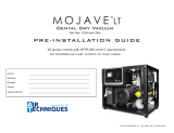
Figure 9. MOJAVE V15 Pump and CT12 Tank Connection Diagram
Important:
Make sure to efficiently use space by making connections as short and direct as possible to
meet your particular site requirements.
Make sure that all hose connections are straight and secure without any sharp bends or kinks.
Since the vacuum hose is rigid, make sure not to stress connections especially at the pump inlet.
Facility Piping from
Operatory
1
Tank Inlet
Detail
Tank Inlet
Flexible Coupling
Connector
CT12 Tank
Tank Air Outlet
to Pump Inlet
Connection
V15 Pump
2
Pump Inlet
Connection Detail
Single Pump
Tank Outlet
Assembly
Detail 1/4-inch
Vacuum
Sample Port
to Master
Controller
2a

17
V15 Connection Procedure. Using industry standard techniques, make the connections between
the tank and pump with supplied components of accessory packs (P/Ns H5403 & H5501). Refer to
Figures 9 and 10 for the connection diagram and perform the following procedure.
1. Suction Line to Tank Inlet Connection. Refer to Figure 9, item (1).
a. Install 2" flexible coupling (P/N H5159) to the pipe from the operatory.
b. Install the 2" ID, clear hose (P/N 54512) cut for installation between the operatory suction
line and tank inlet and tighten the flexible coupling clamps.
2. Tank Air Outlet to Pump Inlet Connection. Refer to Figure 9, item (2).
a. Install the Single Pump Tank Outlet Assembly (P/N H5459) onto the tank outlet port and
secure with the hose clamp at the base of the outlet assembly. The outlet assembly is
provided with the V15 Tank Outlet Kit (P/N H5501).
b. Connect 1 ½" ID, clear hose (P/N 54521) cut for installation between the compression
adapters of the Single Pump Tank Outlet Assembly and pump air inlet filter. Secure by
tightening the compression nut of both adapters.
c. Install a length of 1/4 inch OD Urethane Tubing (P/N 51453) between the vacuum sample
port and the vacuum inlet port of the Master Controller. See Figure 9, item (2a.)
3. Pump Exhaust Vent Connection. Refer to Figure 10, item (3) and connect the vent hose
(P/N 56057) between the pump and the facility vent line. Secure with two hose clamps
(P/N 89324).
4. Exhaust Vent Assembly Installation. Install the Exhaust Vent Assembly (P/N H5302) to the
bottom end of the facility vent line. Install a length of 1/4 inch OD Urethane Tubing (P/N
51453) between the vent and facility sewer drain. See Figure 10, item (4).
Note: If more than 15 feet of the 1/4 inch OD Urethane Tubing is needed,
order P/N 51453 for additional 15 foot lengths.
5. Tank Drain to Facility Sewer Connection. Connect the last section of 1 ½" ID, clear hose
cut for installation to the tank outlet drain. Secure by tightening the check valve compression
nut. Connect unconnected hose end to the facility sewer drain as necessary. See Figure 10,
item (5).
6. Tank Washout Port to Facility Water Connection. Refer to Figure 10, item (6) and
install a length of 3/8 inch tubing (P/N 19271) between the washout port and the water
solenoid then from the solenoid to water shutoff valve. The tubing is provided with CT12
Tank Accessory Pack, P/N H5489.
7. System Electrical Connections. Refer to the Electrical Connections section and connect the
pump and Master Controller to facility power.
INSTALLATION

18
INSTALLATION
Figure 10. MOJAVE V15 Pump Vent and CT12 Tank Drain Connection Diagram
To Facility
Sewer
Drain
5
6
3/8-inch Washout
Port to Washout
Solenoid and then to
Water Shutoff Valve
Connections
Heat Exhaust
Connection
Detail
4
Exhaust Vent
Assembly
3
Tank Drain
Assembly
MT10 Tank
1/4-inch Vent
Condensation
Drain Port
OR
Note:
a See Installation Note J, page 13,
for required pipe material.
Open Drain
Pipe
Closed Vented
Drain
2” Pipe for
Addition of
Exhaust Vent
Assembly
Facility Exhaust Vent Pipe
(See Note a.)

19
2V15 System Installations.
Note: Each kit provides the required hoses, coupling clamps and adapters. No schedule 40 PVC pipe is
included.
Installation Accessory Packs. Figures 11 and 12 show the hose connections required for all dual
MOJAVE system configuration installations using accessory packs that provide the required hoses,
clamps and adapters as follows:
V15 Pump Accessory Pack, P/N H5403 - supplied with each pump and is used as follows.
• Stack the associated MOJAVE pumps as shown by Figure 6.
• Connect each pump to the facility vent line, connection item (3) on Figure 12.
CT12 Tank Accessory Pack, P/N H5489 - used to make the following connections:
• Between the suction line and tank inlet. Item (1) on Figure 11.
• Install exhaust vent assembly to the facility vent line, connection item (4) on Figure 12.
• The tank outlet drain to the facility sewer drain. Item (5) on Figure 12.
• The washout port to the washout solenoid or water shutoff valve. Item (6) on Figure 12.
2V15 Tank Outlet Kit, H5502 - used to make the connections between the tank air outlet
and each pump inlet. Item (2) on Figure 12.
Installation Setup. Installation of a dual pump MOJAVE system (2V15) configuration consists of
placing the equipment in the proper installation space while making connections between a tank
and pump. Use standard industry guidelines for working with electrical circuits, plumbing and on
electronic equipment as necessary.
1. Refer to Figures 4 and 5 and determine the installation footprint dimensions and connection
requirements. Place the tank and pumps in position as shown by Figure 4.
2. If installing side-by-side configuration, proceed to step 4. If stacking pumps, perform step 3.
3. When stacking pumps, refer to Figure 6 and secure the pumps using hardware supplied
by the Pump Accessory Pack, P/N H5403.
Note: If additional 1 ½" ID, Clear Hose hose is needed, order P/N 54521
(order by the foot)
4. Measure and record distance between each connection point. Cut the supplied hose to
the length required for each connection.
Supplied Components. The supplied components of the 2V15 Tank Outlet Kit, H5502 are listed
below. The supplied components of accessory packs( P/Ns H5403 & H5489) are provided on page 15.
Verify that all listed items were received. If any item is missing, notify your dealer.
Table 5. 2V15 Tank Outlet Kit, H5502
Part No. Description Qty
H5441 Tank Outlet Assembly; Dual Pump Installation 1
54521 1 ½" ID, Clear Hose with Blue Helix 20 FT 1
54512 2" ID, Clear Hose with Blue Helix 4 FT 1
54138 Check Valve Modified 2
H5234 2” Flexible Coupling Connector 2
INSTALLATION

20
INSTALLATION
2V15 Connection Procedure. Using industry standard techniques, make the connections between
the tank and pumps with supplied components of accessory pack (P/N H5489) and 2V15 Tank Outlet
Kit (P/N H5502). Refer to Figures 11 and 12 for the connection diagram and perform the following
procedure.
1. Suction Line to Tank Inlet Connection. Refer to Figure 11, item (1) .
a. Install 2" flexible coupling connector (P/N H5159) to the pipe from the operatory.
b. Install the 2" ID, clear hose (P/N 54512) between the operatory suction line and tank inlet
and secure with 2" flexible coupling connector.
2. Tank Air Outlet to Pump Inlets Connection. Refer to Figure 11, item (2) .
a. Install the Dual Pump Tank Outlet Assembly (P/N H5441) onto the tank outlet port and
secure with the hose clamp at the base of the tank outlet assembly. The outlet assembly is
provided with 2V15 Tank Outlet Kit (P/N H5502).
b. Connect 1 ½" ID, clear hose (P/N 54521) cut for installation between the check valves
of the Dual Pump Tank Outlet Assembly and the air inlet filter of each pump. Secure by
tightening each compression nut.
c. Install a length of 1/4 inch OD Urethane Tubing (P/N 51453) between the vacuum sample
port and the vacuum inlet port of the Master Controller. See Figure 11, item (2a.)
Note: If more than 15 feet of the 1/4 inch OD Urethane Tubing is needed,
order P/N 51453 for additional 15 foot lengths.
Figure 11 MOJAVE Dual Pump and Tank Connection Diagram
Tank Air
Outlet
to Dual
Pumps Inlet
Connections
Stacked V15
Pumps
2
Pump 2 Inlet
Connection Detail
Dual Pump Tank
Outlet Assembly
Detail 1/4-inch Vacuum
Sample Port to
Master Controller
Pump 1 Inlet
Connection Detail
2a
Facility Piping from
Operatory
1
Tank Inlet
Detail
Tank Inlet
Flexible Coupling
Connector
CT12 Tank
Important:
Make sure to efficiently use space by making connections
as short and direct as possible to meet your particular site
requirements.
Make sure that all hose connections are straight and secure
without any sharp bends or kinks.
Since the vacuum hose is rigid, make sure not to stress
connections especially at the pump inlet.
/