Page is loading ...


EKO INSTRUMENTS CO., LTD. - Pyranometer MS-40/MS-40S - Instruction Manual Ver. 7
Pg. 1
1. Index
1. Index 1
2. Important User Information 2
2-1. Contact Infor mat ion 2
2-2. Warranty and Liab ility 2
2-3. Ab out I nstruc tio n Man ual 3
2-4. Env ironm ent 3
2-5. ISO/ IEC 170 25 4
2-6. CE Declar ati on 5
3. Safety Information 7
3-1. Ge neral Warn in gs 7
4. Introduction 9
4-1. Abo ut th e Pyr anom eter Seri es 10
4-2. Fie ld ap plica tions 11
4-3. App licat ion t o the sta ndar ds 12
4-4. Pack age C ont ents 13
5. Getting Started 14
5-1. Par ts Na me a nd D es cri ptio ns 14
5-2. Setu p 16
5-3. Wir in g 19
5-4. C on n ec t io ns 20
5-5. M ea s ur em en ts 29
6. Maintenance & Troubleshooting 33
6-1. Main tena nce 33
6-2. Cali brat ion and M easur ement Unc erta inty 35
6-3. Tro uble s hoo ting 36
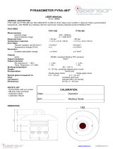
7. Specifications 38
7-1. Spec ific ations 38
7-2. Dim ens io ns 41
7-3. Outp ut cab les 42
7-4. Acc essor ies List 43
Appendix 44
A-1. Ra di ometr ic Terms 44
A-2. Pyra nome ter C har acter istics 45
A-3. Soft ware ( Hib i) 46
A-4. C omm unica tion Spec ifica tions (Mo dbus RT U) 60
A-5. C omm unica tion s pec i fica tion (SDI -12) 72
A-6. Abo ut r ec ali br ati on 74
A-7. MS-40 S Sett ing R epor t 75
A-8. Sur ge pr otec tio n 76

EKO INSTRUMENTS CO., LTD. - Pyranometer MS-40/MS-40S - Instruction Manual Ver. 7
Pg. 2
2. Important User Information
Thank you for using EKO Products
Reading this manual is recommended prior to installation and operation of the product. Keep this manual in a
safe and handy place for whenever it is needed. For any questions, please contact us at below:
2-1. Contact Information
EKO INSTRUMENTS CO., LTD.
Asia, Oceania Region
https://eko-asia.com
EKO INSTRUMENTS Co., Ltd.
1-21-8, Hatagaya, Shibuya-ku
Tokyo, 151-0072 Japan
Tel: +81 [3] 3469-6713
Fax: +81 [3] 3469-6719
Europe, Middle East, Africa, South America Region
https://eko-eu.com
EKO INSTRUMENTS Europe B.V.
Lulofsstraat 55, Unit 28,
2521 AL, Den Haag, The Netherlands
Tel: +31 [0]70 3050117
North America Region
https://eko-usa.com
EKO INSTRUMENTS USA Inc.
111 North Market Street, Suite 300
San Jose, CA 95113 USA
Tel: +1 408-977-7751
Fax: +1 408-977-7741
2-2. Warra nty and Liability
For warranty terms and conditions, please contact EKO Instruments or your distributer for further details.
EKO guarantees that the product delivered to customer has been tested to ensure the instrument meets its published
specifications. The warranty included in the conditions of delivery is valid only if the product has been installed and
used according to the instructions provided in this operating manual.
In case any manufacturing defect[s] occurs, the defected part[s] will be repaired or replaced under warranty; however,
the warranty will not be applicable if:
➢ Any modification or repair has been done by other than EKO service personnel.
➢ The damage or defect is caused by disrespecting the specifications mentioned on the product brochure or
instruction manual.
➢ Spirit level
➢ Discoloration of the pyranometer body, sun screen, and cable within a range that does not affect the function
and performance.

EKO INSTRUMENTS CO., LTD. - Pyranometer MS-40/MS-40S - Instruction Manual Ver. 7
Pg. 3
2-3. Abo ut Instruction Manual
Copyrights Reserved by EKO INSTRUMENTS CO., LTD. Making copies in whole or parts of this document without
permission from EKO is prohibited.
This manual was issued: May. 24, 2022
Version Number: 7
2-4. Envi ronment
1. WEEE Directive 2002/96/EC
[Waste Electrical and Electronic Equipment]
In August of 2005, the European Union [EU] implemented the EU WEEE Directive 2002/96/EC and later the WEEE
Recast Directive 2012/19/EU requiring Producers of electronic and electrical equipment [EEE] to manage and
finance the collection, reuse, recycling and to appropriately treat WEEE that the Producer places on the EU market
after August 13, 2005. The goal of this directive is to minimize the volume of electrical and electronic waste disposal
and to encourage re-use and recycling at the end of life.
EKO products are subject to the WEEE Directive 2002/96/EC. EKO Instruments has labeled its branded electronic
products with the WEEE Symbol [figure Trash bin] to alert our customers that products bearing this label should not
be disposed of in a landfill or with municipal or household waste in the EU.
If you have purchased EKO Instruments branded electrical or electronic products in the EU and are intending to
discard these products at the end of their useful life, please do not dispose of them with your other household or
municipal waste. Disposing of this product correctly will help save valuable resources and prevent any potential
negative effects on human health and the environment, which could otherwise arise from inappropriate waste
handling.
2. RoHS Directive 2002/95/EC
EKO Instruments has completed a comprehensive evaluation of its product range to ensure compliance with RoHS
Directive 2002/95/EC regarding maximum concentration values for substances. As a result, all products are
manufactured using raw materials that do not contain any of the restricted substances referred to in the RoHS
Directive 2002/95/EC at concentration levels in excess of those permitted under the RoHS Directive 2002/95/EC, or
up to levels allowed in excess of these concentrations by the Annex to the RoHS Directive 2002/95/EC.

EKO INSTRUMENTS CO., LTD. - Pyranometer MS-40/MS-40S - Instruction Manual Ver. 7
Pg. 4
2-5. ISO/IEC 17025
EKO Instruments Co. Ltd. calibration laboratory is accredited by Perry Johnson Laboratory Accreditation, Inc. [PJLA]
to perform pyranometer and pyrheliometer calibrations in accordance with the requirements of ISO/IEC17025, which
are relevant to calibration and testing.
EKO is a manufacturer who can offer calibration service for pyranometers and pyrheliometers in-house. Based on
the applied calibration methods EKO provides the best quality solar sensor calibrations compliant to the international
standards defined by ISO9847 [Indoor method] and ISO9059 [Outdoor method] [Certification: L13-94-R2 /
www.pjlabs.com]
ISO/IEC17025 provides a globally accepted basis for laboratory accreditation that specifies the management and
technical requirements. With calibrations performed at the EKO Instruments laboratory we enable our customers to:
- Clearly identify the applied calibration methods and precision
- Be traceable to the World Radiation Reference [WRR] through defined industrial standards:
ISO9846 Calibration of a pyranometer using a pyrheliometer
ISO9847 Calibration of field pyranometer by comparison to a reference pyranometer
ISO9059 Calibration of field pyrheliometers by comparison to a reference pyrheliometer
- Obtain repeatable and reliable calibration test results through consistent operations
Our clients will obtain highly reliable data by using an ISO/IEC17025 calibrated sensor. Our Accredited lab is regularly
re-examined to ensure that they maintain their standards of technical expertise.

EKO INSTRUMENTS CO., LTD. - Pyranometer MS-40/MS-40S - Instruction Manual Ver. 7
Pg. 5
2-6. CE D eclaration
DECLARATION OF CONFORMITY
We: EKO INSTRUMENTS CO., LTD 1-
21-8 Hatagaya Shibuya-ku, Tokyo
151-0072 JAPAN
Declare under our sole responsibility that the product:
Product Name: Pyranometer
Model No.: MS-40
To which this declaration relates is in conformity with the following harmonized
standards of other normative documents:
Harmonized standards:
EN 61326-1:2006 Class A (Emission)
EN 61326-1:2006 (Immunity)
Following the provisions of the directive:
EMC-directive: 89/336/EEC
Amendment to the above directive: 93/68/EEC
Date: June 30, 2017
Position of Authorized Signatory: Deputy General Manager of Quality Assurance Dept.
Name of Authorized Signatory: Shuji Yoshida
Signature of Authorized Signatory:

EKO INSTRUMENTS CO., LTD. - Pyranometer MS-40/MS-40S - Instruction Manual Ver. 7
Pg. 6
DECLARATION OF CONFORMITY
We: EKO INSTRUMENTS CO., LTD 1-21-8
Hatagaya Shibuya-ku, Tokyo 151-0072
JAPAN
Declare under our sole responsibility that the product:
Product Name: Pyranometer
Model No.: MS-40S
To which this declaration relates is in conformity with the following harmonized standards of other
normative documents:
Harmonized standards:
EN 61326-1:2013 Class A (Emission)
EN 61326-1:2013 (Immunity)
Following the provisions of the directive:
EMC-directive: 2014/30/EU
Date: Apr. 15, 2021
Position of Authorized Signatory: Manager of Quality Assurance Div.
Name of Authorized Signatory: Minoru Kita
Signature of Authorized Signatory:

EKO INSTRUMENTS CO., LTD. - Pyranometer MS-40/MS-40S - Instruction Manual Ver. 7
Pg. 7
3. Safety Information
EKO Products are designed and manufactured with consideration for safety; however, please make sure to
read and understand this instruction manual thoroughly to be able to operate the instrument safely in the
correct manner.
WARNING
CAUTION
Attention to user; pay attention to the instructions given on the
instruction manual with this sign.
HIGH
VOLTAGE
WARNING
High voltage is used; pay special attention to instructions given on
this instruction manual with this sign to prevent electric leakage
and/or electric shocks.
3-1. General Warnings
1. Setup
➢ The installation base or mast should have enough load capacity for the instrument to be mounted. Fix
the pyranometer securely to the base or mast with bolts and nuts; otherwise, the instrument may drop
due to a gale or an earthquake, which may lead to unexpected accidents.
➢ Make sure to install the instrument and cables in a suitable location and avoid submersion in water.
➢ Insert the output cable into the connector port on the back of the sensor unit and tighten it all the
way. Push the connector in, and check to make sure the screw is tight. If the connection is loose,
water can enter the unit and cause it to malfunction.
➢ When connecting this product to a measuring instrument for measurement, connect the shield wire of the
output cable to signal ground (SG) for MS-40 and to ground earth for MS-40S. Noises may be included
in the measurement data.
➢ Although this product is tested to meet EMC Directive compliance requirements, it may not fully satisfy
its primary specification/performance when using this product near following locations where strong
electromagnetic wave is generated. Please pay attention to the installation environment.
Outdoor: High voltage power line, power receiver/distribution facility, etc.
Indoor: Large-size chiller, large rotation device, microwave, etc.
➢ Do not use this product in the environment where corrosive gas, such as ammonia and sulfurous acid
gas, are generated. It may cause malfunction.
➢ Do not install in the area that cause salt damages. It may cause malfunction by paint peeling off or
corrosion. When installing in the area with risk of salt damages, make sure to take following measures:
1. Wrap the connector with self-fusing tape
2. Change the fixing screw to bolt screw made of aluminum
3. Run the cables in a plastic or metal pipe treated with salt-resistant paint such as molten zinc plating
4. Periodically clean.
➢ Do not use this instrument in the vacuum environment.
➢ For proper grounding use the original cable provided.

EKO INSTRUMENTS CO., LTD. - Pyranometer MS-40/MS-40S - Instruction Manual Ver. 7
Pg. 8
➢ If the cable and sensor are in risk for getting damaged by birds and small animals, protect the cable and
the sensor by using:
1. Reflective tape
2. Repellent
3. Cable duct
4. Installing bird-spike
➢ When using the configurable 0-1V output from MS-40S, please use a precision shunt resistor 100Ω. The
settings can be changed with the 485 / USB conversion cable and dedicated software.
2. Handling
➢ Be careful when handling instruments with glass dome. Strong impact to this part may damage the glass
and may cause injuries by broken glass parts.
➢ When carrying any MS-40 model with the sun screen attached, always hold the instrument from the
bottom. Holding only the sun screen part may lead to dropping the sensor as it comes off from the sun
screen.
3. Signal Cable [MS-40S]
➢ Make sure to ground the signal cable. When grounding is insufficient, it may cause not only measurement
error due to noise, but also cause electric shock and leakage accidents or damage to the electronics.
➢ Check the voltage and types of specified power supply before connecting this instrument. When improper
power supply is connected, it may cause malfunction and/or accident.
➢ Use this instrument with 0.5A fuse connected to the power supply line in series. Without connecting the
fuse, it has risks of generating heat and fire due to large-current flowing by the power supply when
internal damage of the electronics occurs.
4. About RS-485 Modbus connection [MS-40S]
➢ This product supports communication through the RS-485 Modbus RTU protocol.
➢ It is recommended to use the optional EKO converter cable when connecting MS-40S to a PC.
➢ Depending on the USB-RS485 converter type, an additional termination resistor (120Ω) and/or pull-up/pull-
down resistor (680Ω) may be required for proper communication.
➢ When connecting to a RS-485 (Modbus) master peripheral device, an additional termination resistor (120Ω)
and/or pull-up/pull-down resistor (680Ω) may be required for proper communication.

EKO INSTRUMENTS CO., LTD. - Pyranometer MS-40/MS-40S - Instruction Manual Ver. 7
Pg. 9
4. Introduction
The International Industrial Standard ISO9060 was revised in 2018 to the second edition, and with this the
pyranometers will be classified as "Class A" "Class B" and "Class C" in order descending performance classification.
For the pyranometers that meet the criteria of response time and spectral selectivity, "fast response" and "spectrally
flat" respectively are accompanied as subcategories of grades.
MS-40 is a ISO9060:2018 pyranometer that is classified as Class C and meets the subcategory "spectrally flat".
Alumite-treated, robust, lightweight aluminum body with glass dome provides a well-balanced product of cost
performance and quality.
MS-40/MS-40S is sensitive to the 285 to 3,000nm wavelengths required for measuring solar irradiance, and is
capable of measuring in temperatures as severe as-40°C to +80°C.
The MS-40S provides a variety of industrial signal outputs (MODBUS 485 RTU, configurable SDI-12, 4-20mA,
configurable 0-10mA and 0-1V with precision shunt resistor 100Ω) and advanced measurement functions with on-
board sensors to enable remote diagnosis of the internal temperature and tilt position of the solar radiation meter. It
also has an alert function that alerts the user to abnormalities in the internal humidity of the pyranometer.
MS-40/MS-40S is continuously ventilated in combination with an optional MV-01 (fan + heater unit) to reduce
condensation, dust, and snow accumulation on the glass dome.
Main features
➢ Lightweight aluminum body
➢ Glass dome reduces zero offset
➢ Ventilation unit with heater can be mounted (optional)
➢ Supports several output formats (analogue output (mV), MODBUS 485RTU, configurable SDI-12, 4-20mA,
and configurable 0-1V (external 100 Ω precision shunt resistor)
All MS-40/MS-40S are manufactured by EKO, and calibration is traceable to the Global Standards for Radiation
(World Radiometric Reference) controlled by the World Radiation Center (PMOD/WRC*).
The calibration method of EKO pyranometers is ISO/IEC 17025 accredited and conducted in accordance with the
international standard ISO9847 (indoor calibration).
Accredited calibration facilities undergo periodic reviews and maintain the highest levels of calibration standards and
technical expertise.
This instrument is warranted for a period of 5 years and a recommended recalibration period of 2 years.
(*) PMOD/WRC: Physikalisch-Meteorologisches Observatorium Davos/World Radiation Center

EKO INSTRUMENTS CO., LTD. - Pyranometer MS-40/MS-40S - Instruction Manual Ver. 7
Pg. 10
4-1. About the Pyranometer Seri es
All MS-40 sensors give excellent durability. The sensor is airtight and can be deployed with little maintenance since
the desiccant is incorporated inside. Solar sensors are applied outdoors, hence the detector black surface, optical
components and sensor mechanics are constantly exposed to solar radiation, temperature and pressure
differences. UV radiation known as harmful radiation to materials can change the chemical properties of substances
irreversibly. In the case of the MS-40, the detector is totally isolated below the sensor optics surface, which is
sealed, and can’t be affected by a high dose of UV, moisture or pressure differences.
Besides, EKO provides a unique calibration service for pyranometers compliant to the international standards
defined by ISO9847 [indoor method]. When an ISO/ IEC17025 calibrated sensor is purchased, EKO provides a
calibrated sensor with a consitently low calibration uncertainty. The Accredited lab is regularly re-examined to
ensure that they maintain their standards of technical expertise.
A setting report is provided with all parameters which were set and tested during manufacturing (current range
settings, digital output communication settings).
In case of MS-40, MS-40S, with combination of optional MV-01 [ventilator + heater unit], reduces the dew
condensation and accumulation of dusts and snow on glass dome by continuously blowing heated air. The
ventilation unit with heater is recommended when the sensor is deployed with a chance of occurance of
condensation, snow and ice. IEC 61724-1 Class C monitoring systems should use the MS-40 series pyranometer
with the MV-01 which has a minimum <2W power consumption.
In the following paragraphs, the types are described individually.
1. MS-40
The analog MS-40 pyranometer can be used for optimal performance throughout the day.
Category of ISO9060: 2018
“Spectrally flat pyranometer of class C”

EKO INSTRUMENTS CO., LTD. - Pyranometer MS-40/MS-40S - Instruction Manual Ver. 7
Pg. 11
2. MS-40S
The MS-40S with smart sensor technology and onboard diagnostic functions. 4 different output types can be
selected, which is a great benefit for system integrators who work with various industrial standards. This new Smart
transducer features sensors for remotely diagnosing the internal temperature and tilt angle of the pyranometer, and
an alert function for abnormalities in the internal humidity of the pyranometer. These additional internal sensors and
alert functions will help the user to monitor the stability of the irradiance sensors as well as to ensure its proper
installation and maintenance practices.
Up to 31 smart sensors per one Master can be connected in one network. The signal converter settings can be
changed using the optional RS485 / USB converter cable and the configurator software.
Category of ISO9060: 2018
“Spectrally flat pyranometer of class C”
Key features:
- Outputs (Modbus 485 RTU, configurable SDI-12, 4-20mA, configurable 0-1V with external 100Ω precision
shunt resistor)
- Low power consumption
- Wide voltage-supply input range [5 to 30 VDC]
- With built-in tilt / roll sensor to check the sensor position over time.
- Temperature and humidity sensors to monitor the inside temperature of the pyranometer and condition of the
drying agent (silica gel) inside the pyranometer body
- Alert function to notify abnormal condition of internal humidity of the pyranometer
4-2. Field applications
The MS-40 analog sensor is well suited to be used in traditional meteorological networks where analog sensors are
still common. The MS-40S with digital (Modbus 485 RTU / SDI-12) can be used in a multi sensor network for onsite
monitoring of large PV plants. Digital sensor can be easily configured, With the MS-40S, users can connect using a
standard laptop and ‘Hibi’; a new, custom built programme developed by EKO to give users real-time access to the
internal diagnostics, custom settings, and data on irradiance, internal temperature and tilt angle from the sensor. This
data can also be acquired when the pyranometer is connected through the data logger digital serial communication
port. Each pyranometer has it own unique communication address. This way multiple pyranometers can be connected
in a network.
The MS-40S builds on the revolutionary qualities of the original MS-40 by adding a new internal diagnostics system,
giving users remote visibility internal temperature, internal humidity status, tilt and roll angle; helping them to ensure
optimum performance without the need for regular physical checks. Coupled with the 2-year recalibration interval,
the internal diagnostic capabilities of the MS-40S makes it an ideal solution for complex networks, hard to reach
locations, and monitoring stations with restricted access.

EKO INSTRUMENTS CO., LTD. - Pyranometer MS-40/MS-40S - Instruction Manual Ver. 7
Pg. 12
4-3. Applicati on to th e stand ards
MS-40/MS-40S models are qualified to be used within any application which refers to an international standard
according to:
- ISO9060: 2018 Spectrally flat pyranometer class C (Pyranometer classification)
- IEC 61724-1:2017 Class C (PV monitoring system requirement)
- WMO-No. 8, seventh edition 2018 Moderate quality pyranometer (Meteorological system requirement)
- ISO/TR 9901:1990 (Solar energy field pyranometers recommended practice for use)
- ASTM G183 - 05 (Standard Practice for Field Use of Pyranometers)
MS-40/MS-40S models comply to the international standards for calibration and traceable to the WRR:
- ISO 9847 Calibration of field pyranometers by comparison to a reference pyranometer
- ISO 9846 Calibration of a pyranometer using a pyrheliometer
- ISO/IEC 17025:2017 scope of accreditation

EKO INSTRUMENTS CO., LTD. - Pyranometer MS-40/MS-40S - Instruction Manual Ver. 7
Pg. 13
4-4. Package Contents
Check the package contents first; if any missing parts or any damage is noticed, please contact EKO immediately.
Table 4-1. Package Contents
Item
MS-40
MS-40S
Pyranometer
○
Output cable
○(1)
Sun screen
○
Instruction Manual
Not included in the package
[Please download from EKO Website]
Setting Report
-
○
Calibration certificate
○
Quick Start Guide
○
Fixing Bolts
[M5] × 2
[Bolt Length: 75mm]
Washers
[M5] × 4
Nuts
[M5] × 2
(1) The standard length of the Output cable for the MS-40 / MS-40S is 10 m. If you need a cable longer than 10 m,
please contact EKO or your local distributer.

EKO INSTRUMENTS CO., LTD. - Pyranometer MS-40/MS-40S - Instruction Manual Ver. 7
Pg. 14
5. Getting Started
5-1. Parts Name and Desc riptions
Each part name and its main function is described below.
1. Glass dome
Glass dome serve to protect the detector from raindrops, snow, and dust, and have an important role in cutting
unwanted wavelengths so that only the wavelengths required for the measurement of global pyranometers reach the
detector.
By making the glass dome-shaped, light from all directions of the hemisphere can be transmitted with little reflection.
(View angle: 180 degrees) and double structure make it less susceptible to changes in output due to wind, etc.
Names of parts
A. Glass Dome
B. Detector
C. Body
D. Leveling Screw
E. Cable/Connector
F. Cable/Connector
G. Spirit level
H. Drying agent
I. Sun screen
MS-40 / MS-40S
Table 5-1. Part Names
[MS-40 / MS-40S]
*Signal converter is built-in for MS-40S.
Figure 5-1. Pyranometer Parts Name [MS-40/MS-40S]
E
F
A
B
C
G
H
D

EKO INSTRUMENTS CO., LTD. - Pyranometer MS-40/MS-40S - Instruction Manual Ver. 7
Pg. 15
2. Detector
Thermopile, which generates a voltage proportional to temperature difference [Seebeck Effect], is used for the
detector. When light is irradiated on the sensor, temperature of the detector increases; creating the temperature
difference at cold junction [body part] will generate an electromotive force on the thermopile. The pyranometer will
output this electromotive force as voltage and measuring this voltage will determine the solar irradiance. The
thermopile detector, which is the heart of the sensor, determines the majority of the measurement properties [e.g.,
response time, zero offset B, non-linearity, sensitivity, etc.]. EKO thermopile detectors are very stable in time due to
the black absorber material, which has high absorption, and no wavelength dependency is used on the detector
surface.
3. Sun screen/Body
MS-40 and MS-40S have a sun screen to prevent any excessive body temperature increase generated by direct sun
light.Weather resistant metals are used to reduce the effects and degradation caused by heat radiation, rain, and
windblown dusts.
4. Spirit level
The integrated sprit level is used to setup and maintain the sensor in a horizontally leveled position.
* Depending on the operating environment, bubbles may come out of the level gauge, liquid may be missing, the
reference circles may fade out, or cracks may occur.
5. Drying agent
Enclosed drying agents inside the sensor body keep the sensor inside dry, prevents condensation of humidity inside
of the glass dome.
6. Cable/connector
All pyranometers are shipped with a 10-meter-long output cable as standard length*.
Durable materials are used for the cable and connector, and pin terminals are attached at the end of the cable for
easy connection with data logger terminal block.
*If longer cables, round terminals or fork terminals are required, please contact EKO Instruments or your distributor.
[Also see [7. Specification, 7-4. Accessories List] for optional items.]
The connector should be protected by the self-fusing tape when the pyranometers are used in the areas with the risk
of the salt damage.

EKO INSTRUMENTS CO., LTD. - Pyranometer MS-40/MS-40S - Instruction Manual Ver. 7
Pg. 16
5-2. Setup
In order to obtain representative measurements from pyranometers, several criteria with respect to setup and
mounting of the instruments have to be considered.
The ideal mounting position for pyranometers is a location which has a full hemispheric field-of-view without any
obstructions [such as buildings, trees, and mountain]; however, it might be difficult to find such locations. Therefore,
in practice, it is ideal to install in a position which is free from obstructions at 5° above horizon.
The setup location should be easily accessible for periodic maintenance [glass dome cleaning, etc.], and avoid
surrounding towers, poles, walls or billboards with bright colors that can reflect solar radiation onto the pyranometer.
A strong physical impact to the pyranometer can lead to product damage and/or may cause changes to the sensitivity.
1. Installing at Horizontal or Tilted Position
1) Check the installation base where the pyranometer must be mounted and make sure it has two fixing holes
with the appropriate pitch. The pitch sizes of the fixing holes are as follows [in mm]:
Table 5-2. Fixing Hole Pitch and Bolt Size for Pyranometers
MS-40 / MS-40S
Fixing Hole Pitch
65 mm
Fixing Bolt Size
M5 x 75 mm
2) Remove the sun screen.
The sun screen can be removed by loosening the knurled screw and sliding it towards the spirit level direction.
*When carrying the MS-40 with sun screen attached, always hold the instrument from the bottom. Holding only
the sun screen part may lead to dropping the sensor as it comes off from the sun screen.
Setup the pyranometer with the signal cable connector facing the nearest Earth’s pole.
In the Northern hemisphere, the connector should be orientated North, in the Southern hemisphere, the
connector should be orientated South. If the signal cable connector is facing towards the sun, the temperature
of the connector increases and may cause measurement error due unwanted thermoelectric power invited by
the connector temperature increase.

EKO INSTRUMENTS CO., LTD. - Pyranometer MS-40/MS-40S - Instruction Manual Ver. 7
Pg. 17
3) There are two ways to setup the pyranometer (Horizontal or Tilted Position).
Installing at horizontal Position
Adjust the pyranometer in a horizontal position by using the 2 levelling screws observing the air bubble in the
spirit level while manipulating the levelling screws. The instrument is levelled horizontally if the air bubble is in the
centre ring. The sensitivity of the bubble vial is (0.1º / mm). If the pyranometer is not levelled properly, the
pyranometer readings are affected by cosine and azimuth errors. Periodically check the spirit level and adjust the
pyranometer’s position if necessary.
Installing at Tilted Position
After the MS-40, MS-40S is adjusted to horizontal position on a levelled surface, install it on tilted a tilted mount.
When installing the pyranometer, do not remove the levelling feet or fixed feet. If the levelling
feet are removed, it may induce offsets to output values due to the thermal effects from the
mounting plate.
In the case of MS-40S, it is possible to acquire tilt
information obtained from the built-in tilt position
sensor through Modbus RTU. The sensor position
can be measured in two different planes (X,Y).
<Tilt (X axis)> (180º to 0) and (0 to -180º)
<Roll (Y axis)> (180º to 0) and (0 to -180º)
The tilt and roll angles are relative to the calibrated X and Y axis of the sensor and surface mounting plane X’
and Y’. When the sensor is positioned in the same plane X = X’ and Y = Y’, the measured tilt and roll angles (X
and Y) correspond to plane of installation X’ and Y’.
Figure 5.2A Tilt angle (-180 to 0º) and (0 to 180º)
Roll angle (-180 to 0º) and (0 to 180º)
-X
X
Y
-Y

EKO INSTRUMENTS CO., LTD. - Pyranometer MS-40/MS-40S - Instruction Manual Ver. 7
Pg. 18
The pyranometer connector is an important reference for setup and corresponds to the X-axis
reference plane.
For setup at horizontal plane: Setup the pyranometer with the signal cable connector facing
the nearest Earth’s pole. In the Northern hemisphere, the connector should be orientated
North, in the Southern hemisphere, the connector should be orientated South. Even if the
cable is not oriented to the nearest pole, it does not affect the angle measurement. The angle
measurement reflects the tilt and roll of the corresponding sensor position.
For setup at tilted position: Setup the pyranometer with signal cable aligned with the
installation platform (X’, Y’), see figure 5-2B. When the sensor is not aligned, the tilt (X) and
roll (Y) measurement does not reflect the angle X’ and Y’, see figure 5-2C.
4) Fasten the pyranometer to the base with the 2 bolts [included] and put the sun screen back on the pyranometer.
+Y
-X
X’
Y’
-Y
+X
X’
Y’
Figure 5-2B Tilt and roll angle
corresponding to reference plane
Figure 5-2C Tilt and roll angle not
corresponding to reference plane

EKO INSTRUMENTS CO., LTD. - Pyranometer MS-40/MS-40S - Instruction Manual Ver. 7
Pg. 19
5-3. Wiring
To extend the cable lifetime, make sure that the cables are not exposed to direct sun light or rain/wind by lining the
cable through a cable conduit. Cable vibrations will potentially cause noise in the output signal. Fasten the cable so
that the cable does not swing or move by wind blowing. Exposure of the signal cable to excessive electromagnetic
emissions can cause noise in the output signal as well. Therefore, the cable should be lined at a safe distance from
a potential source generating EMC noise, such as an AC power supply, high voltage lines or telecom antenna.
1. Shield wire connection
<MS-40>
Please be sure to connect the shield wire of the cable to the SG of the measurement equipment
side. If it is not connected, it may be affected by noise.
<MS-40S>
The pyranometer housing is connected to the shield wire of the cable, so connect the shield wire
to the ground on the measurement equipment side.
Do not connect the pyranometer housing to ground. It will be a two-point ground and it cause a
noise.
2. Wiring procedure
Connect the output cable to the MS-40 / MS-40S: Insert the output cable into the connector port on the
back of the sensor unit, and twist clockwise to fasten it. Make sure to tighten the connector all the
way.
1) If the connection is loose, water can enter the unit and cause it to malfunction.
2) Secure the length of the cable to avoid it from being pulled loose.
3) Connect the power cable grounding wire to prevent electrical shocks.
Cable shield wire
SG(Signal ground)
Measurement Device
Connect the shield wire of the cable to SG on
the measurement equipment side.
MS-40
Figure 5-3A. MS-40 shield wire connection method
Cable shield wire
FG
Measurement Device
Measurement instrument side ground
Connect the shield wire of the cable to FG on
the measurement equipment side.
MS-40S
Figure 5-3B. MS-40S shield wire connection method
/