Page is loading ...

_ Technical
GAS UNITS j _:_bic=lo.s
KITS AND ACCESSORIES LithoU,S.A,
©1997 Lennox industries inc.
Datlas, Texas
503,771M
10/97
FURNACE TRANSITION KIT
INSTALLATION INSTRUCTIONS FOR FURNACE TRANSITION KIT CAT# 16L44
(LB-93421A), AND CAT# 16L45 (LB-93422A) USED WHEN CONVERTING FROM GSR14
UNITS TO GHR26 UNITS (HORIZONTAL)
Package 1 of 1 contains:
1 - Insulated supply air transition
1 - Insulated return air transition
4- Base rails
1 - Base brace
16 - #8 sheet metal screws
1 - Roll of adhesive-backed foam tape (1/8" thick x
5/16" wide)
Check all components for shipping damage. Consult
last carrier immediately if damage is found.
Table 1 shows furnace transition kit usage. These kits
are used when replacing an existing GSR14
horizontal furnace with a GHR26 horizontal furnace, tt
allows installation of the GHR26 furnace without
modification of the existing supply and return air
plenums.
Note - GHR26 units can only be installed left side
discharge when using these transition kits.
Note - Some GSR14 units may have been installed
with little or no clearance to the unit's top side. Since
the GHR26 unit's vent exits this side, interference
may be encountered, ff it is, field fabricated
transitions may be required.
Refer to figure 1for typical GSR14 installation.
1 - Set the thermostat to the lowest setting.
2 - Disconnect electrical power to GSR14 unit.
3- Shut off gas to GSR14 unit.
4 - Disconnect supply and return air plenums.
5 - Remove control access panel,
6 - Cut combustion air intake pipe and exhaust pipe
in location(s) which will allow convenient
reconnection of pipes to GHR26 unit, and/or
removal of muffler(s) (if installed), Remove
muffler(s) (if installed). Support intake and
exhaust pipes to prevent damage to pipe joints,
7 - Cut condensate drain line in a location which will
allow convenient reconnection with GHR26 unit.
8 - Disconnect gas line at unit.
9 - Disconnect power wiring at unit,
10 -Disconnect low voltage wiring at unit.
11 -Remove blower access panel.
12 -Remove filter from inside of unit (if present) and
disconnect return air plenum at unit.
Note - Existing GSR14Q4/5-80/100 filter can be
used in GHR26Q4/5-100 units.
13 -Remove GSR14 unit.
TABLE 1
GSR14 CABINET WIDTH GHR26 CABINET WIDTH KIT CAT# (LB#)
inches (mm) inches (mm)
Q3-50 21-1/4 (540) Q2/3-50 16-1/4 (413) 16L44 (LB-93421A)
Q3-80 2t-1/4 (540) Q3-75 t6-1/4 (413) 16L44 (LB-93421A)
Q4/5-80 21-1/4 (540) Q4/5-100 21-1/4 (540) 16L45 (LB-93422A)
Q4/5-t00 21-1/4 (540) Q4/5-100 21-1/4 (540) 16L45 (LB-93422A)
Note - There is no direct replacement for GSR14Q4-50 unit with a GHR26 unit.
Page 1

TYPICAL GSR14 HORIZONTAL APPLICATION
INTAKE PIPE
3T PIPE
CONTROL
ACCESS PANEL
SUPPORT
_FRAME
GASCONNECTOR-------
DRAIN PAN
FIGURE 1
Page 2

Note - Installation must conform with these
instructions and the installation instructions
packaged with the GHR26 furnace.
Note - The overall dimensions of the GHR26 and the
awkwardness of handling the GHR26 are increased
once transitions are installed.
A - Return Air Transition installation.
Refer to figure 2,
1 - Lay GHR26 unit on its back (exposed internal parts
facing up), (Figure 2 shows installed position.)
2 - Remove the three rear-most cabinet screws at
return air inlet (3 each side),
3 - Cut two strips from roll of adhesive-backed foam
tape (provided) to fit two cabinet sides as shown
in figure. Apply to cabinet sides.
4 - Install transition as shown.
5-Install filter as shown in GHR26 installation
instructions. GHR26Q4!5-100 unit will accept
installation of GSR14Q4/5-80!100 unit filter.
GHR26-50 and -75 units require a field provided
14x25x1 filter.
B - Supply Air Transition Installation.
Refer to figure 2.
t - Remove the three rear-most cabinet screws at
supply air inlet (3 each side).
2 - Cut two strips from roll of adhesive-backed foam
tape (provided) to fit two cabinet sides as shown
in figure. Apply to cabinet sides.
3 - Install transition as shown.
C - Base Rails Installation,
Refer to figure 2
1 - Install base rails as shown in figure 2.
D - Unit Installation
1 - Align unit with existing supply air plenum (coil
cabinet in air conditioning applications) and
return air plenum, Make connections to unit.
2- Connect low voltage wiring as illustrated in
GHR26 installation instructions.
3-Connect high voltage wiring as outlined in
GHR26 installation instructions.
4-Connect gas piping as outlined in GHR26
installation instructions.
Consult local codes for flexible connector
installation restrictions on GHR26 furnace.
5- Connect venting as outlined in GHR26
installation instructions,
Note - Mufflers can not be used in GHR26
installation. Check existing venting for size
(diameter and length). It should meet the
specifications as outlined in GHR26 installation
instructions. If a concentric vent is used for
GHR26-100 unit, it must be identified as catalog
number 33K97.
6 - Connect heat exchanger condensate drain line as
outlined in GHR26 unit installation instructions.
Note - Coil drain line must not be connected to
heat exchanger condensate drain line. ff lines
were connected, debris from evaporator could
affect heat exchanger operation.
7 - Continue with Unit Start-up Section as outlined
in GHR26 installation instructions,
Note - See GHR26 installation instructions for heat
anticipation settings.
Page 3

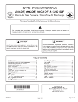
SUPPLY AIR OUTLET
ADHESIVE BACKED FOAM TAPE
REAR-MOST BLOWER _'_
DECK HOLE
TYPICAL GHR26 INSTALLATION
(LEFT SIDE DISCHARGE ONLY - INSTALLED POSITION SHOWN)
S EXISTING REAR-MOST
CABINET SCREW
I
ADHESIVE BACKED FOAM TAPE
CONTROL ACCESS
SUPPLY AIR TRANSITION
INSTALLATION -
(identify transition by its !7" x 20-3/8"
432mm x 518mm) plenum connection
size)
1 - Apply foam tape as shown.
2 -Align transition holes with the
three rear-most cabinet holes.
Return air transition holes will
not align in this position.)
Cabinet extends 2-3/8 inches
beyond transition at front.)
3 - Secure transition to cabinet
with existing screws. In re-
maining hole use self-drilling
self-tapping screw.
DRAIN LINE ROUTING HOLE
/
I
I
I
I
BRACE
HOLE"A"
FRONT BASE RAIL SET
RETURNAIR INLET
BLOWER ACCESS PANEL
DRAIN LINE ROUTING HOLE
REAR BASE RAIL SET
RETURN AIR TRANSITION INSTALLATION -
(identify transition by its 19-1/8" x 24"
(486mm x 619mm) plenum connection
size)
1 - Apply foam tape as shown.
2 - Align transition holes with three
the rear-most cabinet holes.
(Supply air transition holes will
not align in this position)
(Cabinet extends 2-3/8 inches
beyond transition at front.)
3 - Secure transition to cabinet
with existing screws. In remaining hole
use self-drilling self4apping screw.
SECURING SCREWS
SECURING
SCREWS
VIEW A
_" DETAIL B AIR TRANSITION
BASE RAILS INSTALLATION
A - Assemble rails: BASE RAIL TO TRANSITION JOINT
1 - Orient two rails used to form front rail set as shown in view A.
(Position drain line routing hole as shown.)
2 - Repeat for rear rail set.
3 - Position brace between front and rear rail sets as shown in main figure.
4 - Attach brace to rail sets with the four screws provided.
B - Attach rail assemb]y to transitions and unit:
1 - Remove rear-most blower deck screw.
2 - Align rear rail hole "A'as shown in main figure
with rear most blower deck hole.
3 - Secure rear rail set to unit and transitions. (See main figure and detail B)
4 - Repeat for front rail set using third blower deck hole from rear.
FIGURE 2
Page 4
/