Page is loading ...

Graco Inc. P.O. Box 1441 Minneapolis, MN 55440-1441
Copyright 2009, Graco Inc. is registered to I.S. EN ISO 9001
313347C
AA30 Air Assisted Spray Gun
Models: 257096, RAC Tip; 257380, Flat Tip
Maximum Working Pressure: 3600 psi (248 bar, 24.8 MPa)
Maximum Air Working Pressure: 100 psi (7 bar, 0.7 MPa)
Important Safety Instructions
Refer to your sprayer instruction manual for Pressure Relief
and spray instructions. Keep these instructions.
- For the application of architectural paints and coatings -
The following Warnings are for the setup, use, grounding, maintenance and repair of this equipment. The exclamation
point symbol alerts you to a general warning and hazard symbols refer to procedure-specific risks. Refer back to these
Warnings. Additional, product-specific warnings may be found throughout the body of this manual where applicable.
SKIN INJECTION HAZARD
High-pressure fluid from gun, hose leaks, or ruptured
components will pierce skin. This may look like just a
cut, but it is a serious injury that can result in amputation. Get
immediate surgical treatment.
• Do not point gun at anyone or at any part of the body.
• Do not put your hand over the spray tip.
• Do not stop or deflect leaks with your hand, body,
glove, or rag.
• Do not spray without tip guard and trigger guard
installed.
• Engage trigger lock when not spraying.
• Follow Pressure Relief Procedure in this manual, when
you stop spraying and before cleaning, checking, or servic-
ing equipment
.
FIRE AND EXPLOSION HAZARD
Flammable fumes, such as solvent and paint fumes, in
work area can ignite or explode. To help prevent fire
and explosion:
• Use equipment only in well ventilated area.
• Eliminate all ignition sources; such as pilot lights, cig-
arettes, portable electric lamps, and plastic drop
cloths (potential static arc).
• Keep work area free of debris, including solvent, rags
and gasoline.
• Do not plug or unplug power cords, or turn power or
light switches on or off when flammable fumes are
present.
• Ground all equipment in the work area. See Ground-
ing instructions.
• Use only grounded hoses.
• Hold gun firmly to side of grounded pail when trigger-
ing into pail.
• If there is static sparking or you feel a shock, stop
operation immediately. Do not use equipment until
you identify and correct the problem.
• Keep a working fire extinguisher in the work area.
EQUIPMENT MISUSE HAZARD
Misuse can cause death or serious injury.
• Do not operate the unit when fatigued or under the
influence of drugs or alcohol.
• Do not exceed the maximum working pressure or
temperature rating of the lowest rated system compo-
nent. See Technical Data in all equipment manuals.
• Use fluids and solvents that are compatible with equip-
ment wetted parts. See
Technical Data
in all
equip-
ment manuals. Read fluid and solvent manufacturer’s
warnings. For complete information about your mate-
rial, request MSDS forms from distributor or retailer.
• Check equipment daily. Repair or replace worn or
damaged parts immediately with genuine manufac-
turer’s replacement parts only.
• Do not alter or modify equipment.
• Use equipment only for its intended purpose. Call
your distributor for information.
• Route hoses and cables away from traffic areas,
sharp edges, moving parts, and hot surfaces.
• Do not kink or over bend hoses or use hoses to pull
equipment.
• Keep children and animals away from work area.
• Comply with all applicable safety regulations.
PRESSURIZED ALUMINUM PARTS HAZARD
Do not use 1,1,1-trichloroethane, methylene chloride,
other halogenated hydrocarbon solvents or fluids con-
taining such solvents in pressurized aluminum equipment. Such
use can cause serious chemical reaction and equipment rup-
ture, and result in death, serious injury, and property damage.
PERSONAL PROTECTIVE EQUIPMENT
You must wear appropriate protective equipment when
operating, servicing, or in the operating area of the
equipment to help protect you from serious injury. This
equipment includes but is not limited to:
• Protective eyewear and hearing protection
Gloves, clothing and respirator as recommended by the
fluid and solvent manufacturer
WARNINGS
ti12849a
English

2 313347C
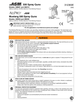
Component Identification
Pressure Relief Procedure
Follow this Pressure Relief Procedure whenever
instructed to relieve pressure, stop spraying, check or
service equipment, or install or clean spray tip.
1. Turn OFF power and turn sprayer pressure control to
lowest pressure setting.
2. Hold gun against side of grounded metal flushing pail.
Trigger gun into pail to relieve pressure.
If you suspect spray tip or hose is clogged or that
pressure has not been fully relieved after following the
steps above, VERY SLOWLY loosen tip guard retaining
nut or hose end coupling to relieve pressure gradually,
then loosen completely. Clear hose or tip obstruction.
Trigger Lock
To prevent injury when gun is not in use, always set gun
trigger lock (A) if sprayer is turned off or left unattended.
Setup
Make sure sprayer is turned off and unplugged from
power source. Refer to your sprayer instruction manual
for priming and spray instructions.
Connect Gun to Sprayer
1. Attach air hose.
NOTE: The first time you set
up the gun for spraying you
will have to cut the black air
hose to length desired.
2. Attach fluid hose.
3. See Setup instructions in
sprayer operation manual
(313316).
ID Component ID Component
A Trigger lock E Air on/off valve
B Spray Tip F Air hose connection
C Safety RAC guard G Air adjustment valve
D Trigg er H Fluid hose connection
H
G
F
D
B
C
E
A
ti12849a
WARNING
WARNING
(A)
(B)
ti10352a
ti10353a
ti13318a
ti13317a

Operation
313347C 3
Tip and Guard on Gun
AA30 Gun with RAC Tip (257096)
1. Relieve pressure, page 2.
2. Insert seat housing (27)
into guard (29).
3. Insert SwitchTip (28).
4. Insert seal (27b) over
seat (27a) and insert in
seat housing (27). Use black seal for water-based
materials and orange for solvent and oil-based
materials.
5. Install guard (6) over end of gun. Hand tighten firmly
to ensure a good seal.
6. Replace seat (33a) and/or retighten guard nut if you
notice fluid leaking from front of gun.
AA30 Gun with Flat Tip (257380)
1. Relieve pressure, page 2.
2. Insert spray tip into flat tip air
cap assembly. Insert spray tip
locating tab (A) into air cap
locating slot (B).
3. Install guard over end of gun.
Hand tighten firmly to ensure a
good seal.
Operation
Note: The following instructions are for guns used with
Graco FinishPro Sprayers. See the sprayer instruction
manual 313316. If you are using a different sprayer, see
your equipment instruction manual.
Setup
1. Prime sprayer. See manual 313316.
2. Slide air on/off valve on (up).
3. Turn air adjustment valve off at
gun.
4. Increase fluid pressure to
eliminate tails.
5. Decrease fluid pressure until
just before tails start to
appear.
6. Increase air pressure with air
adjustment valve to eliminate
tails.
7. Slide air on/off valve off (down)
when finished spraying to save
proper air pressure setting.
Spray
1. Unlock trigger lock.
2. Be sure the arrow shaped tip (B) faces forward
(spray) (257096).
3. Hold gun perpendicular and approximately 12 in.
(304 mm) from surface. Move gun first, then pull gun
trigger (D) to spray a test pattern.
4. Do not spray in an arc. This causes an uneven fluid
coat. Spray in a path parallel to the surface, with a
50% overlap, to obtain an even fluid coat.
NOTICE
If air cap is not fully installed on gun, fluid pressure
can force paint into air line and damage sprayer.
27a
29
28
27
27b
ti8249a
A
B
ti13263a
ti12855a
ti13321a
ti13279a
ti13280a
ti13281a
WRONG
RIGHT

Maintenance
4 313347C
Clearing RAC Tip Clogs (257096)
1. Relieve pressure. Set trigger lock (A).
2. Rotate tip (B) 180°. Unlock trigger lock (A). Trigger
gun into pail or onto ground to remove clog.
3. Set trigger lock (A). Rotate tip (B) 180° back to spray
position.
Maintenance
Before performing any maintenance on gun, read all
warnings on front cover of this manual and relieve
pressure.
Daily Maintenance
Flush gun after each work shift and store in a dry location.
Do not immerse the gun or any parts in water or cleaning
solvents.
• Do not point gun up while cleaning it.
• Do not wipe gun with cloth soaked in solvent; wring
out excess.
• Solvent left in gun air passages could result in a poor
quality paint finish. Do not use any cleaning method
that may allow solvent into gun air passages.
Flushing and Cleaning
• Flush gun before changing colors, before storing and before
repairing gun.
• Flush at lowest possible pressure. Check connectors for
leaks and tighten as necessary.
• Flush with fluid compatible with fluid being dispensed and
equipment wetted parts.
1. Relieve pressure. Unplug sprayer.
2. Remove tip (28) and guard (29).
3. Remove sprayer siphon tube set from paint and place
in flushing fluid. See Cleanup instructions in sprayer
operation manual 313316.
4. Plug sprayer in outlet. Set sprayer function selection
switch to AIRLESS or ON.
5. Increase pressure slowly. Point gun down into
grounded metal container. Pull gun trigger and flush
gun with solvent until all traces of fluid are removed
from gun passages.
6. Turn sprayer function selection switch to OFF.
7. Relieve pressure, page 2.
8. Disconnect fluid supply hose from gun.
9. If it is necessary to remove diffuser (5) to clean, follow
Needle Replacement Removal procedure, steps 1
through 6.
10. Dip soft-bristle brush into a compatible solvent. Do
not use a wire brush.
11. Point gun down, clean front of gun with soft-bristle
brush and solvent.
12. Scrub tip (28) and guard (29) with soft-bristle brush.
Clean air cap holes with a toothpick to avoid
damaging critical surfaces. Blow air through spray tip
(28) to ensure orifice is clean.
13. If diffuser (5) was removed, trigger gun while you
reinstall diffuser. Torque to 26-32 ft-lb (36-40 N•m).
When properly tightened, flange bottoms out on gun.
14. Install air cap manifold; follow Needle Replacement
Installation procedure, steps 9 - 13.
15. Install tip (28) and guard (29) on gun, page 2.
16. Wipe off outside of gun with soft cloth dampened in
solvent,
Cleaning/Replacing Filter (6)
1. Relieve pressure. Set trigger lock (11a).
2. Disconnect fluid hose from gun at swivel (5).
3. Disconnect bracket (36) from retainer (16) and swivel
out of way.
4. Place a wrench on flats below handle and loosen
from gun.
5. Unscrew handle (14) from gun (1).
6. Remove filter (6) through top of handle (14).
7. Clean filter (6). Use a soft brush to loosen and
remove excess debris.
8. Insert clean filter (6) into handle (14).
9. Reattach handle (14) to gun (1). Tighten securely.
10. Place a wrench on flats below handle and tighten
securely.
11. Connect bracket (36) to retainer (16).
WARNING

Needle Replacement
313347C 5
Needle Replacement
Removal
1. Relieve pressure, page 2. Set trigger lock (11a).
2. Disconnect air hose from gun.
3. Disconnect bracket (36) from retainer (16) and swivel
bracket out of the way
4. Remove tip (28) and guard (29), Parts, page 7, from
air cap manifold (26).
5. Release trigger lock (11a). Squeeze trigger (11).
Remove set screw (39) at base of air cap manifold
(26). Unscrew air cap manifold from front of gun (26).
6. Squeeze trigger. Remove diffuser housing (3).
7. Remove locknut (10) and end cap (9).
8. Tap needle assembly (8), Parts, page 7, out, with
needle exiting through front of gun.
9. Use a soft brush to clean out internal passages of
gun.
Installation
1. Apply non-silicon grease to o-rings of new needle.
2. Guide new needle (8), Parts, page 7, through front of
gun.
3. Loosely install end cap (9) and locknut (10).
4. Grease threads of needle housing (3).
5. Squeeze trigger (11) and install diffuser (5). Torque
to 26-32 ft-lb (36-40 N•m).
6. Hold gun with nozzle facing up.
7. Turn locknut (10) clockwise until you see and feel
trigger (11) raise slightly.
8. Turn locknut (10) 3/4 turn counter-clockwise.
NOTE: Needle is properly adjusted when trigger moves
freely.
9. Screw air cap manifold
(26) on until end of
manifold is flush with end
of diffuser housing (5).
26
15
11a
9
10
5
1
11
3
ti12852a
8
NOTICE
The end of the diffuser housing must be flush or
sticking out beyond the manifold in order to ensure a
proper seal.
ti12851a

Technical Data
6 313347C
10. If air tube is not in downward position, continue to
thread manifold until it is.
11. Connect bracket (36) to retainer (16).
12. Pull trigger (11) and install set screw (39). Torque set
screw to 10 - 12 in-lb (1,1 - 1,4 N•m).
13. Install tip (28) and guard (29). Tighten securely.
14. Connect air hose.
Test Needle Installation
1. Prime sprayer. See sprayer instruction manual.
2. Trigger gun into bucket until fluid flows from gun.
3. Release trigger (11). Fluid flow stops immediately.
4. Set trigger lock (11a).
5. Aim gun into bucket. Trigger gun. No fluid show flow.
6. If gun fails tests of steps 3 and/or 5, relieve pressure
and disconnect hose. Readjust needle. Repeat tests.
Technical Data
Maximum inlet fluid pressure 3600 psi (24,8 MPa, 240 bar)
Maximum inlet air pressure 100 psi (0,7 MPa, 7 bar)
Air inlet 1/4 nps
Fluid inlet 1/4 nps
Sound levels per ISO 3744
Sound power level less than 65.0 dB(A)
Sound pressure level less than 65.0 dB(A)
Wetted parts
Bare spray gun stainless steel, aluminum
Translated Manuals
Bulgarian- 313371 Dutch - 313351 German - 313355 Latvian - 313359
Portuguese - 313363
Slovenian - 313367
Croatian - 313348 Estonian - 313352 Greek - 313356
Lithuanian - 313360
Romanian - 313364 Spanish - 313368
Czech - 313349 Finnish - 313353
Hungarian - 313357 Norwegian - 313361
Russian - 313365 Swedish - 313369
Danish - 313350 French - 313354 Italian - 313358 Polish - 313362 Slovakian - 313366 Turkish - 313370

Parts
313347C 7
Parts
1
2
3
8b
8a
6
7
8
8c
11
12
13
14a
14b
16
22
9
7
26a
26d
26c
31
27
29
30
32a
32f
32e
32e
32d
32c
32b
33
26b
28
8d
26e
43
42
44
26f
47b
46
47a
24
ti12853a
Ref. Part Description Qty.
1 15W295 HOUSING, fluid (plated) 1
2✓ 179733 SEAL, sleeve 1
3 195419 HOUSING, needle 1
6✓ 288750 FILTER, gun, latex, 100 mesh 1
288749 FILTER, gun, latex, 50 mesh 1
256975 FILTER, gun, latex, 150 mesh 1
7 115484 PIN, actuator 2
8 KIT, needle 1
257526 GUN Model 257096 (includes 8a, 8b, 8c)
257527 GUN Model 257380 (includes 8b, 8c, 8d)
8a HOUSING, diffuser, assembly 1
8b 156766 GASKET 1
8c 115483 NUT, lock 1
8d HOUSING, diffuser, assembly, flat 1
9 15W164 CAP, end 1
11 256963 TRIGGER, gun, 2 finger, assembly 1
12 177538 STUD, trigger 1
13 105334 NUT, lock, hex 1
14 257781 KIT, repair, handle AA30 (includes 14a, 14b) 1
14a HANDLE, gun 1
14b SWIVEL, gun 1
16 15W291 RETAINER, guard 1
22 278003 HANDLE, gun 1
24 122530 O-RING 1
26 KIT, repair, manifold 1
257783 GUN Model 257096 (includes 26a, 26b, 26c,
26d)
257784 GUN Model 257380 (includes 26c, 26d, 26e,
26f)
26a MANIFOLD, air cap, RAC 1
26b 120775 O-RING 1
26c 15W160 GASKET, tube 2
26d 111102 SCREW, set 1
26e MANIFOLD, air cap, flat 1
26f 122486 O-RING 1
27 15J770 HOUSING, RAC 1
28✓ FFT210 TIP 1
29✓ 288465 GUARD, RAC, Alpha G40 1
31 257078 TUBE, air, assembly 1
32 257782 KIT, repair, valve, slide (includes 32a-32f)
32a BODY, valve 1
32b FITTING, adapter 1
32c O-RING 1
32d BRACKET, air tube 1
32e O-RING 2
32f SLEEVE, valve 1
33 288715 VALVE, swivel, ASM 1
42✓ AAM411 TIP, G15, G40 1
43 111116 O-RING, seat 1
44✓ 249256 TIP, guard 1
46 249180 AIR CAP 1
47 253032 AIR CAP Seal Kit (includes 47a, 47b)
47a 109213 PACKING, o-ring PTFE 1
47b 15G320 WASHER, PTFE 1
▲ Replacement Warning labels, tags, and cards are available at no
cost.
✓
Keep these spare parts on hand to reduce downtime.
Ref. Part Description Qty.

Graco Standard Warranty
8 313347C
Graco Standard Warranty
Graco warrants all equipment referenced in this document which is manufactured by Graco and bearing its name to be free from defects in material
and workmanship on the date of sale to the original purchaser for use. With the exception of any special, extended, or limited warranty published by
Graco, Graco will, for a period of twelve months from the date of sale, repair or replace any part of the equipment determined by Graco to be defective.
This warranty applies only when the equipment is installed, operated and maintained in accordance with Graco’s written recommendations.
This warranty does not cover, and Graco shall not be liable for general wear and tear, or any malfunction, damage or wear caused by faulty
installation, misapplication, abrasion, corrosion, inadequate or improper maintenance, negligence, accident, tampering, or substitution of non-Graco
component parts. Nor shall Graco be liable for malfunction, damage or wear caused by the incompatibility of Graco equipment with structures,
accessories, equipment or materials not supplied by Graco, or the improper design, manufacture, installation, operation or maintenance of structures,
accessories, equipment or materials not supplied by Graco.
This warranty is conditioned upon the prepaid return of the equipment claimed to be defective to an authorized Graco distributor for verification of the
claimed defect. If the claimed defect is verified, Graco will repair or replace free of charge any defective parts. The equipment will be returned to the
original purchaser transportation prepaid. If inspection of the equipment does not disclose any defect in material or workmanship, repairs will be made
at a reasonable charge, which charges may include the costs of parts, labor, and transportation.
THIS WARRANTY IS EXCLUSIVE, AND IS IN LIEU OF ANY OTHER WARRANTIES, EXPRESS OR IMPLIED, INCLUDING BUT NOT LIMITED TO
WARRANTY OF MERCHANTABILITY OR WARRANTY OF FITNESS FOR A PARTICULAR PURPOSE.
Graco’s sole obligation and buyer’s sole remedy for any breach of warranty shall be as set forth above. The buyer agrees that no other remedy
(including, but not limited to, incidental or consequential damages for lost profits, lost sales, injury to person or property, or any other incidental or
consequential loss) shall be available. Any action for breach of warranty must be brought within two (2) years of the date of sale.
GRACO MAKES NO WARRANTY, AND DISCLAIMS ALL IMPLIED WARRANTIES OF MERCHANTABILITY AND FITNESS FOR A PARTICULAR
PURPOSE, IN CONNECTION WITH ACCESSORIES, EQUIPMENT, MATERIALS OR COMPONENTS SOLD BUT NOT MANUFACTURED BY
GRACO. These items sold, but not manufactured by Graco (such as electric motors, switches, hose, etc.), are subject to the warranty, if any, of their
manufacturer. Graco will provide purchaser with reasonable assistance in making any claim for breach of these warranties.
In no event will Graco be liable for indirect, incidental, special or consequential damages resulting from Graco supplying equipment hereunder, or the
furnishing, performance, or use of any products or other goods sold hereto, whether due to a breach of contract, breach of warranty, the negligence of
Graco, or otherwise.
FOR GRACO CANADA CUSTOMERS
The Parties acknowledge that they have required that the present document, as well as all documents, notices and legal proceedings entered into,
given or instituted pursuant hereto or relating directly or indirectly hereto, be drawn up in English. Les parties reconnaissent avoir convenu que la
rédaction du présente document sera en Anglais, ainsi que tous documents, avis et procédures judiciaires exécutés, donnés ou intentés, à la suite de
ou en rapport, directement ou indirectement, avec les procédures concernées.
ADDITIONAL WARRANTY COVERAGE
Graco does provide extended warranty and wear warranty for products described in the “Graco Contractor Equipment Warranty Program”.
TO PLACE AN ORDER, contact your Graco distributor or call to identify the nearest distributor.
or call 1-800-690-2894 to identify the nearest distributor.
All written and visual data contained in this document reflects the latest product information available at the time of publication.
Graco reserves the right to make changes at any time without notice.
This manual contains English. MM 313347
Graco Headquarters: Minneapolis
International Offices: Belgium, China, Japan, Korea
GRACO INC. P.O. BOX 1441 MINNEAPOLIS, MN 55440-1441
www.graco.com
04/2009
/