Page is loading ...

For music with passion
User's Manual
CYCLONE
large scale mixing console
LTO
R
www.altoproaudio.com
English
LTO
R
Version 1.0 APRIL. 2006

SAFETY RELATED SYMBOLS
CAUTION
RISK OF ELECTRIC SHOCK
DO NOT OPEN
This symbol, wherever used, alerts you to the pre-
sence of un-insulated and dangerous voltages with-
in the product enclosure. These are voltages that
may be sufficient to constitute the risk of electric
shock or death.
Protective Ground Terminal
AC mains (Alternating Current)
Hazardous Live Terminal
ON: Denotes the product is turned on.
This symbol, wherever used, alerts you to impo-
rtant operating and maintenance instructions.
Please read.
OFF: Denotes the product is turned off.
WARNING
Describes precautions that should be observed to
prevent the possibility of death or injury to the user.
CAUTION
Describes precautions that should be observed to
prevent damage to the product.
Protective Ground
Operating Conditions
IMPORTANT SAFETY INSTRUCTIONS
Cleaning
Servicing
Power Cord and Plug
the recommended fuse type as indicated in this
manual. Do not short-circuit the fuse holder. Before
replacing the fuse, make sure that the product is
OFF and disconnected from the AC outlet.
Before turning the product ON, make sure that it is
connected to Ground. This is to prevent the risk of
electric shock.
Never cut internal or external Ground wires. Likewise,
never remove Ground wiring from the Protective
Ground Terminal.
Always install in accordance with the manufacturer's
instructions.
To avoid the risk of electric shock and damage, do
not subject this product to any liquid/rain or moisture.
Do not use this product when in close proximity to
water.
Do not install this product near any direct heat source.
Do not block areas of ventilation. Failure to do so
could result in fire.
Keep product away from naked flames.
Read these instructions
Follow all instructions
Keep these instructions. Do not discard.
Heed all warnings.
Only use attachments/accessories specified by the
manufacturer.
Do not tamper with the power cord or plug. These are
designed for your safety.
Do not remove Ground connections!
If the plug does not fit your AC outlet seek advice from
a qualified electrician.
Protect the power cord and plug from any physical
stress to avoid risk of electric shock.
Do not place heavy objects on the power cord. This
could cause electric shock or fire.
When required, either blow off dust from the product
or use a dry cloth.
Do not use any solvents such as Benzol or Alcohol.
For safety, keep product clean and free from dust.
Refer all servicing to qualified service personnel only.
Do not perform any servicing other than those instruc-
tions contained within the User's Manual.
Fuse
To prevent fire and damage to the product, use only
No user serviceable parts inside.
Power Supply
Ensure that the mains source voltage (AC outlet)
matches the voltage rating of the product. Failure
to do so could result in damage to the product and
possibly the user.
Unplug the product before electrical storms occur
and when unused for long periods of time to reduce
the risk of electric shock or fire.
External Connection
Always use proper ready-made insulated mains
cabling (power cord). Failure to do so could result
in shock/death or fire. If in doubt, seek advice from
a registered electrician.
Do Not Remove Any Covers
Within the product are areas where high voltages
may present. To reduce the risk of electric shock do
not remove any covers unless the AC mains power
cord is removed.
Covers should be removed by qualified service
personnel only.
WARNING
1
Disposing of this product should not be
placed in municipal waste and should be
Separate collection.

Dear Customer:
Thank you for choosing the LTO CYCLONE which is the result of our LTO AUDIO TEAM's endeavours.
For LTO AUDIO TEAM music and audio are much more than a job, they are a passion and an obsession!
We have, in fact, been designing professional audio products for a number of years in cooperation with many of the
world's major brands.
The LTO line represents unparalleled analogue and digital products made by musicians, for musicians. With our
design centres in Italy, the Netherlands, and the United Kingdom we provide you with world-class designs, while our
software development teams continue to develop an impressive range of audio specific algorithms.
By purchasing our LTO products you become the most important member of our LTO AUDIO TEAM. We would
like to share with you our passion for what we design and we invite you to make suggestions, which will aid us in de-
veloping future products for you. We guarantee you our commitment to quality, continual research and development,
and of course the best performance/price ratio.
The LTO CYCLONE is a large format versatile 4-bus sound reinforcement mixing console designed for all types
of live sound production as well as for recording purposes. Each channel is equipped with a variety of key features
including a warm, natural sounding four band sweep EQ (4 band fixed EQ for stereo channels), 6 Auxiliary sends,
CYCLONE.
We would like to thank all the people that worked with us to make a vision real! Our designers and LTO staff made
the LTO CYCLONE, the large format 6-bus sound reinforcement mixing console, a very reliable and high quality product
ready for all your venues. And thanks to their passion for music and professional audio it has been possible for us to
offer you, our most important team member, our continued support too.
Thank you very much
LTO AUDIO TEAM
PREFACE
2
Level Set preamp and fader LEDs etc.. Besides, the CYCLONE is equipped with fully featured oscillator and talkback
sections that will allow the sound engineer to work in a very fast and reliable way. Seeing is believing, let's meet LTO

TABLE OF CONTENTS
SAFETY INSTRUCTIONS
PREFACE
TABLE OF CONTENTS
INTRODUCTION
MAIN FEATURES
INSTALLATION AND CONNECTIONS
CYCLONE PICTURES
FUNCTIONAL DESCRIPTION
CYCLONE CONNECTIONS WIRING
..........................................................................................................................1
...................................................................................................................................................2
.............................................................................................................................3
........................................................................................................................................4
......................................................................................................................................5
......................................................................................................6
...............................................................................................................................8
.................................................................................................................10
Cyclone Mono input channels ................................................................................................................10
Cyclone Stereo input channels ..............................................................................................................15
Cyclone Master Section .........................................................................................................................20
......................................................................................................28
...............................................................................................................................38
..............................................................................................................39
TECHNIQUE & TROUBLESHOOTING
GLOSSARY
BLOCK DIAGRAMS
TECHNICAL SPECIFICATIONS
WARRANTY
...................................................................................................32
..............................................................................................................................................37
.............................................................................................................................................41
3

Our current top mixer line...fitted with a wide range of controls to satisfy the needs of the most demanding professional
with its real hi-fi specs and its user-friendly and ergonomic design despite the very high quantity of controls! These
models are ideal for large venue and large bands.
Thank you very much for expressing your confidence in LTO products by purchasing LTO's large format mixing
console Cyclone, an 4-bus sound reinforcement mixing console designed for all types of live sound production. We're
proud to introduce you our large format mixing console, designed and developed to meet the needs of the demanding
live sound engineers, providing the quality, all the features and the reliability you deserve, with its real hi-fi specs and
its user-friendly and ergonomic design despite the very high quantity of controls!
Following the needs of professional live sound engineers we included a lot of special features, like the Talkback section
the frequency Oscillator, one CLIP and one Level Set indicator to immediately understand at a glance the behaviour of
every channel mono signal.
The Cyclone is a large format professional mixing console. You will get a smooth, accurate more natural and open
sound from this tool, it is really ideal for gigs, recording and fixed PA installations.
Your Cyclone has been designed to be a very versatile and user-friendly mixing console, so it's very easy to operate
but we advise you to go through each section of this manual carefully. In this way you will get the best out of your
Cyclone in all application.
INTRODUCTION
4
The Cyclone is an all purpose FOH mixing console that can be used as Monitor mixer as well, thanks to its 6 inde-
pendent auxiliary sends. Each mono channel offers microphone and line input and insert points, lo-cut filter, four band
Sweep EQ. etc. The stereo channel offers stereo (left & right) line input with four band fixed EQ, as well as mono input
with discrete mic &line connections and Low-cut filter.

MAIN FEATURES
Pre-insert preamp Level Set LED
Extremely high headroom offering excellent dynamic range
Each input channel features Mute & SOLO switches, Overload & signal present LEDs and low cut filters
5
Pre-fader, pre-eq channel insert
MIC input channels with golden plated XLRs and balanced LINE inputs
2-band fixed and 2-band sweep EQ on mono channels
4 Stereo input channels with left-right balanced TRS jacks, and mono MIC
4-band fixed EQ on stereo channels
Ultra-low noise discrete Mic Preamps with +48V Phantom Power
100mm high precision faders
Fader CLIP LED
SUB 1-2-3-4 & MAIN L-R signal assignment switch
6 AUX all individually assignable pre/post with AFL mode.
Channel insert on each mono channel for connection of outboard equipment
Main Mix insert for flexible connection of outboard equipment
and4 AUX return inputs can output from AUX1-6 PLF output.
Fully assignable Oscillator and Talkback sections
2-TRACK IN path
Highly accurate 8 segment output level meters
XLR socket for lighting lamps

INSTALLATION AND CONNECTIONS
6
The following counsels must be observed to maintain safety and electromagnetic compatibility performance in order
to obtain the best possible performances by your Cyclone.
Earthing & Power Connections
Please try to avoid placing the console close/on any power distribution units or power amplifiers.
When using an external power supply, it should be located as far as possible from the console.
The power supply should be set for the voltage supply available in your area and plugged into the mains socket using
the cable provided with the ground/screen connector properly connected. The Cyclone should only be operated with
the power supply connected to ground via the ground in the mains connector. The use of alternative power supplies
may cause damage and void the warranty.
The power supply should never be operated with the mains earth disconnected
Please note that the power supply contains DANGEROUS VOLTAGES, much stronger than the mains voltage.
The power supply rails can produce extremely large currents which could burn out equipment and wiring if shorted.
Electric & Magnetic Fields
When the console is operated close to an electromagnetic field (generated by video monitors, high-power electric
cabling, etc.), you should detect an audio degradation induced by voltage picked up by leads and chassis. In this case
the signal to noise ratio may be degraded, under extreme conditions (3V/m, 90% modulation) degradation of up to
40dB may be experienced.
Wiring
To ensure the correct and reliable operation of your Cyclone mixing console, only high quality screened twisted pair
audio cable and metal bodied connectors should be used.
Position
Place the mixing console on a flat and even surface, avoiding extremely hot, cold, dust or humid places.
Your Cyclone should be situated so that its location or position does not interfere with its proper ventilation (e.g. on
a carpet, on felt, etc.).
When positioning the console for front of house usage it is worth placing the console in the " " positionsweet spot
(where the sound system used can be properly heard from the mix position). Try to avoid placing the console behind
pillars or large objects , or mixing from a level above the speaker position (e.g. from a balcony).
WARNING: Always switch off the power supply before connecting or disconnecting the mixer power cable, removing
or installing modules, and servicing. In the event of an electric storm or large mains voltage fluctuations,
immediately switch off your Cyclone and disconnect the mains plug from its socket.
WARNING: Do not replace the fuse with any other type, or short-circuit the broken fuse, this could become
a safety hazard and will void the warranty.
WARNING: All servicing should ONLY be carried out by skilled personnel of an authorized maintenance centre.
[ INSTALLATION ]
Since all the signals are referenced to earthing system, it's very important that it's clean and noise free. The best way
to do an earthing system is to use a "star fed" instead of "daisy chain". A "star fed" earth connection means that in-
dependent wires runs for each outlet, in this way you'll provide a safety reference screen for each single equipment.
Never mix the mains audio earthing outlets with light earthing outlets, it could very easily generate interferences and
audio degradation.

[ CONNECTIONS ]
All connector shells should be of metal construction in order to provide a screen when connected to the console.
The Cyclone deserves to be operated with high quality twisted-pair audio cables to develop its full audio performances.
XLR plug & socket
Pin 1 - Screen/Ground
Pin 2 - Hot Signal
Pin 3 - Cold Signal
6,3mm. (1/4") Jack - BALANCED connections
TRS signal
Sleeve Screen/Ground
Ring Cold signal
Tip Hot signal
6,3mm. (1/4") Jack - unbalanced connections
TS signal
Sleeve Screen/Ground
Tip Signal
6,3mm. (1/4") TRS insert
Sleeve Screen/Ground
Ring Insert return
Tip Insert send
6,3mm. (1/4") TRS headphone
Sleeve Screen/Ground
Ring Right signal
Tip Left signal
Owner's manual conventions
Writing this owner's manual we used the following conventions:
1. The names of the keys switches and connectors used in this owner's manual match the labels on the unit
Examples: MIC IN -> Microphone input
MID-H -> Mid-High frequency boost/cut control
GR1-GR2 -> Group 1 & Group 2
2. The condition of the indicators on your mixer is surrounded by " ", e.g. or ."light" "flash"
7

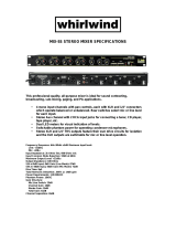
CYCLONE PICTURES
8
CYCLONE 160
CYCLONE 240

9
CYCLONE PICTURES
CYCLONE 320

[ Cyclone Mono Input Channels ]
The Cyclone is supplied with all the connections which pro users deserve to connect every kind of signal sources to
Cyclone inputs.
FUNCTIONAL DESCRIPTION
10
Insert
This unbalanced 1/4" jack connector has been designed to be used as insert
point, breaking the signal path immediately after the preamp section and
before the EQ section to allow the pro user to insert a dynamic compressor,
a parametric EQ, as well as other ancillary equipment. Please note that the
Mute switch of the channel does not affect this connector. The wiring is
Tip = Insert Send, Ring = Insert Return, Sleeve = Screen.
Line in
This balanced input connector has been designed to accept line inputs up
to +22dBu. You can connect here keyboards outputs, mixer outputs, tape
outputs, etc. The wiring is Tip = Hot, Ring = Cold, Sleeve = Screen.
MICROPHONE in
This XLR socket has been designed to accept microphone signals up to
+22dBu, providing phantom power for condenser microphone when the
switch in the front panel is engaged. Pin1 = Screen/Ground, Pin2 = Hot
Signal, Pin3 = Cold Signal.
MIC IN
MIC IN
LINE IN
INSERT
INSERT
LINE IN
CH 2CH 2 CH 1CH 1

We perfectly know the importance of the preamp section, a good preamp section will allow the sound engineer to work
with maximum dynamics, an exceptional signal-to-noise ratio... then to be able to use EQ, external dynamic controls
and other ancillary equipment to shape its own sound!
The Cyclone preamp section features all the useful controls to accurately manage the sound source in the most ver-
satile way.
11
[ Cyclone Mono Input Channels ]
PHANTOM POWER switch & LED
The switch must be engaged when you're using a condenser microphone
or a direct box that can be powered by phantom power, instead of batteries.
The LED gives the user a visual control over channels with phantom
power on.
GAIN & LEVEL SET LED
The GAIN control gives you the chance to continuously adjust the preamplifier
gain for input signal. This control can be adjusted in 0/+60dB range for microphone
input and -25/+35dB for line input. The LEVEL SET LED will help the sound engineer to immediately detect the input level. In
this case the research of the fault will become much faster!
HIGH PASS switch & LED
This section allows the sound engineer to reduce the lower frequencies by engaging the switch This control is very useful
when you detect hum or rumble or you want to cut unwanted low frequency sounds picked-up by microphones. The LED
shows if the HIGH PASS section is active or not.
PHASE switch & LED
This switch allows the user to invert by 180 the signal. This switch is very
useful in a lot of circumstances, in particular when several microphones are
very close (e.g. drum kit, brasses, chorus, etc.) and the sound engineers notices
interferences between microphones that can not be solved moving the
microphones. The LED gives an immediate control over channels with inverted
phase electronic circuits.
0
HIGH PASS
-25
+35
+60
GAIN
LEVEL
SET
PHANTOM 48V
PHASE

We provided a very versatile EQ circuit with two sweep filters to satisfy professional users demand. Thanks to the
wide overlap section of the 4 filters, this EQ allows to shape in a very efficient way the sound of all the sound sources
which the sound engineers has to manage.
12
[ Cyclone Mono Input Channels ]
HIGH gain
It's a shelving filter giving the user a continuous adjustment of boost
and cut from +15dB to -15dB @15KHz.
MID-H gain
It's a peak/dip filter giving the user a continuous adjustment of boost
and cut from +15dB to -15dB @800~8KHz.
MID-L gain
It's a peak/dip filter giving the user a continuous adjustment of boost
and cut from +15dB to -15dB @160~1.6KHz.
LOW gain
It's a shelving filter giving the user a continuous adjustment of boost and cut from +15dB to -15dB @80Hz.
MID-H freq
It's the control to set the centre frequency of the MID-H control. It can
be adjusted in 800~8kHz range. It affects the frequency area from the
upper fundamental frequencies up to the higher harmonic frequencies,
allowing the skilled user to add or to subtract brightness to sound sources
to avoid masking frequencies effects.
MID-L freq
It's the control to set the centre frequency of the MID-L control. It can
be adjusted in 160~1.6kHz range. It affects the frequency area of most
of fundamental tone frequencies up to lower harmonic frequencies,
allowing the skilled user to add/subtract impact and/or presence to
sound sources giving them a particular sound character.
HIGH
15KHz
0dB
MID-H
EQ
MID-H
freq
KHz
8
MID-L
0dB
MID-L
freq
Hz
16K.
160
640
LOW
80Hz
0dB
.8
0dB
-
15
+
15
-
15
+
15
-
15
+
15
-
15
+
15
32.

At LTO we thought that you deserve a very versatile auxiliary section. So we provided you six auxiliary sends.
These AUX sends can control the signals level which come from AUX output, but they have no effect to the main output.
AUX 1
The AUX 1 send level can be adjusted from - up to +10dB.
AUX 2
The AUX 2 send level can be adjusted from - up to +10dB.
AUX 3
AUX 4
13
[ Cyclone Mono Input Channels ]
The AUX 3 send level can be adjusted from - up to +10dB.
The AUX 4 send level can be adjusted from - up to +10dB.
AUX 5
The AUX 5 send level can be adjusted from - up to +10dB.
AUX 6
The AUX 6 send level can be adjusted from - up to +10dB.
+
10
-
8
0dB
0dB
0dB
0dB
AUX1
AUX2
AUX3
AUX4
AUX5
AUX6
0dB
0dB
0dB
-
15
+
15
+
10
-
8
+
10
-
8
+
10
-
8
+
10
-
8
+
10
-
8

The assign section is useful to manage the output assignment to several outputs, listen "in Solo" a channel and mute
or not a channel signal.
OUTPUT Assign to 1/2, 3/4, L/R
These switches allow the sound engineer to address the signal to selected audio
path. The odd/even numbered switches are used to send the signal to sub-groups
while L/R switch sends the signal directly to Main Mix output.
Please check the "technique & trouble-shooting" section of this owner's manual for
further details about the way to use those switches.
PAN
This pot allows the sound engineer to place the channel signal in a stereo front from
hand left to hand right. Of course you can use it also to "move" the channel signal in
stereo front to create spatial effects.
MUTE
You can use the MUTE switch to mute the channel signal when you don't need its
sound.
Fader
This long coarse fader will give the sound engineer the ability to accurately manage
channel output level from - up to +10dB.
the
14
[ Cyclone Mono Input Channels ]
-20 & CLIP LEDs
These LEDs are very useful to control the behaviour of the channel signal path
after the EQ section and before the fader. In this both cases the presence of two
CLIP LEDs will help the sound engineer to immediately detect where is the problem.
PFL switch
This switch allows the sound engineer to control the channel signal. The PFL
(pre-fade listen) signal is pre-fader and mono When this large switch is engaged,
it's illuminated to give you an immediate visual control of which, and how many
channels are in PFL.
PFL
ON
OFF
CH 1
10
5
5
10
20
30
40
50
60
-
0
8
1
2
MUTE
CLIP
-20
PAN
Right
Left
centre
3
4
L
R

[ Cyclone Stereo Input Channels ]
15
Each Cyclone is supplied with four stereo input channels. These channels are ideal for stereo signals but we included
the same circuit of mono inputs, with discrete preamp level section and low-cut filter. So the sound engineer has the
choice to use a mono signal and a stereo signal outputs in the same channel in different times without being obliged
to change the GAIN control!
RIGHT
This balanced input connector has been designed to accept line
inputs up to +22dB. This connector should be only used for the
right output of an instrument. The wiring is Tip = Hot, Ring = Cold,
Sleeve = Screen.
LEFT IN (MONO)
This balanced input connector has been designed to accept line
inputs up to +22dB. This connector should be used for the left or
mono output of an instrument. This input follows the stereo path.
The wiring is Tip = Hot, Ring = Cold, Sleeve = Screen.
MICROPHONE in
This XLR socket has been designed to accept microphone signals
up to +22dB, providing phantom power for condenser microphone
when the switch in the front panel is engaged. Pin1 = Screen/
Ground, Pin2 = Hot Signal, Pin3 = Cold Signal.
MIC IN
RIGHT
MIC IN
LEFT IN (MONO)
RIGHT
LEFT IN (MONO)
ST1ST2

HIGH PASS switch & LED
This section allows the sound engineer to reduce the lower frequencies of MONO INPUT
by engaging the switch This control is very useful when you detect hum or rumble or
you want to cut unwanted low frequency sounds picked-up by microphones. The LED
shows if the HIGH PASS section is active or not.
16
[ Cyclone Stereo Input Channels ]
The Cyclone preamp section is fully featured with all the useful controls to manage the sound source. There are two
different preamp input path for mono or stereo signals, the latter features just GAIN while the mono preamp input is
regularly featured like any other mono input. In this way the sound engineer can use, for example, the stereo keyboard
outputs in the same channel of the entertainer voice, if both signals are not required at the same time and each source
will has its own level control.
MONO IN GAIN & LEVEL SET LED
PHANTOM POWER switch & LED
The switch must be engaged when you're using a condenser microphone or a direct box that can be powered by phantom
power, instead of batteries. The LED gives the user a visual control over channels with phantom power on.
PHASE switch & LED
This switch allows the user to invert by 180 the signal. This switch is very useful in a lot of circumstances, in particular
when several microphones are very close (e.g. drum kit, brass, choirs etc.) and the sound engineer notices interferences
between microphones that can't be solved by moving the microphones. The LED gives an immediate control over
channels with inverted phase electronic circuits.
STEREO IN GAIN
The GAIN control gives you the chance to uously adjust the amplifier gaincontin
for & RIGHT inputs. This control -20/+20dBLEFT (MONO) can be adjusted in
range input.
INPUT SELECT switch
Pressing this switch you'll select the mono input source for this channel, while
releasing this switch you'll use the stereo signal.
INPUT SELECT LED
This LED is lit when you use a mono signal, the INPUT SELECT switch is pressed.
STEREO IN
GAIN
INPUT SELECT
MONO
STEREO
0 +60
PHANTOM 48V
HIGH PASS
20 20
+
-
PHASE
MONO IN
GAIN
LEVEL
SET
The GAIN control gives you the chance to continuously adjust the preamplifier gain for input signal. This control can be
adjusted in 0/+60dB range for microphone input. The LEVEL SET LED will help the sound engineer to immediately detect
the input level. In this case the research of the fault will become much faster!

Stereo sources are generally keyboards outputs, pre-mixers, etc., so the signal deserves few EQ adjustments. For
this reason we choose for the Cyclone stereo channels a four band fixed EQ.
HIGH gain
It's a shelving filter giving the user a continuous adjustment of boost and
cut from +15dB to -15dB @ 12kHz.
MID-L
It's a peak/dip filter giving the user a continuous adjustment of boost and
cut from +15dB to -15dB @ 400Hz.
MID-H
It's a peak/dip filter giving the user a continuous adjustment of boost and
cut from +15dB to -15dB @ 3kHz.
LOW
It's a shelving filter giving the user a continuous adjustment of boost and
cut from +15dB to -15dB @ 80Hz.
17
[ Cyclone Stereo Input Channels ]
LOW
80Hz
0dB
0dB
EQ
0dB
0dB
-
15
+
15
-
15
+
15
-
15
+
15
-
15
+
15
MID-L
MID-H
HIGH
12KHz
3KHz
400Hz

At LTO we thought that you deserve a very versatile auxiliary section. So we provided you the same six discrete
auxiliary sends of mono channels, with independent level controls.
AUX 1
The AUX 1 send level can be adjusted from - up to +10dB.
AUX 2
The AUX 2 send level can be adjusted from - up to +10dB.
18
[ Cyclone Stereo Input Channels ]
AUX 3
The AUX 3 send level can adjusted from -
be up to +10dB.
AUX 4
The AUX 4 send level can abe djusted from - up to +10dB.
AUX 5
The AUX 5 send level can abe djusted from - up to +10dB.
AUX 6
The AUX 6 send level can abe djusted from - up to +10dB.
0dB
0dB
0dB
0dB
0dB
0dB
AUX1
AUX2
AUX3
AUX4
AUX5
AUX6
+
10
-
8
+
10
-
8
+
10
-
8
+
10
-
8
+
10
-
8
+
10
-
8

The assign section is useful to manage the output assignment to several outputs, and also to PFL or MUTE a channel
signal.
19
[ Cyclone Stereo Input Channels ]
OUTPUT Assign to 1/2, 3/4, L/R
BAL
This pot allows the sound engineer to manage the balance of a stereo source
or to place the channel mono signal in a stereo front from hand left to hand
right. Of course you can use it to "move" the channel signal in stereoalso
front to create spatial effects.
Fader
This long coarse fader will give the sound engineer the ability to accurately
manage the channel output level from - up to +10dB.
MUTE
You can use the MUTE switch to mute the channel signal when you don't
need its sound. When this large switch is engaged, it's lit.
PFL
ON
OFF
ST1
10
5
5
10
20
30
40
50
60
-
0
8
1
2
MUTE
CLIP
-20
BAL
Right
Left
centre
3
4
L
R
PFL switch
These switches allow the sound engineer to address the signal to the selected
audio path. The odd/even numbered switches are used to send the signal to
sub-groups while L/R switch sends the signal directly to Main Mix output. Please
check the "technique & troubleshooting" section of this owner's manual for further
details about the way to use those switches.
This switch allows the sound engineer to control the channel signal. The PFL
(pre-fade listen) signal is pre-fader and stereo for stereo inputs and mono for
mono inputs. When this large switch is engaged, it's illuminated to give you
an immediate visual control of which, and how many channels are in PFL.
-20 & CLIP LEDs
These LEDs are very useful to control the behaviour of the channel signal
path after the EQ section and before the fader. In this both cases the presence
of two CLIP LEDs will help the sound engineer to immediately detect where
is the problem.
/