Page is loading ...

Cat. No. 62029-18
APA 6000™ High and Low Range Copper
Process Analyzer
Operation Manual
© Hach Company, 2001, 2002. All rights reserved. Printed in the U.S.A.
dd/dp 02/02 2ed

Page 2
Table of Contents
6202918TOC.fm
Table of Contents
Safety Precautions.................................................................................................................................................... 3
Specifications............................................................................................................................................................ 4
Operation ............................................................................................................................................................... 5
Section 1 Instrument Overview ........................................................................................................................ 6
1.1 How to Use the Manuals..................................................................................................................................... 6
1.2 General Description............................................................................................................................................ 6
1.2.1 Instrument Enclosure................................................................................................................................. 6
1.2.2 Autoburette Module ................................................................................................................................... 6
1.2.3 Colorimeter Module and Holding Coil........................................................................................................ 7
1.2.4 Rotary Valve Module ................................................................................................................................. 7
1.2.5 Mixer Module............................................................................................................................................. 7
1.2.6 Plumbing Diagram and Tubing Lengths..................................................................................................... 7
1.2.7 Vortex Sample Conditioning Block............................................................................................................. 8
1.2.8 Copper Reagents ...................................................................................................................................... 8
Section 2 Theory of Operation........................................................................................................................ 10
2.1 Method of Analysis............................................................................................................................................ 10
2.2 Reagent and Standard Consumption................................................................................................................ 11
Section 3 Parameter Specific Menu Functions........................................................................................... 12
3.1 Calibration History............................................................................................................................................. 12
3.2 Measurement Options....................................................................................................................................... 12
Section 4 Sequence of Instrument Events ............................................................................................ 13
Section 5 Bench Comparison Testing .......................................................................................................... 17
5.1 Comparable Bench Methods............................................................................................................................. 17
5.2 Bench Method Procedure ................................................................................................................................. 17
5.3 Determining Copper Concentration in Samples................................................................................................ 19
Section 6 Replacement Parts.......................................................................................................................... 20

Page 3
6202918 safety.fm Safety Precautions
Safety Precautions
If multiple hazards exist, this manual will use the signal word (Danger, Caution, Note)
corresponding to the greatest hazard.
Read all labels and tags attached to the instrument. Personal injury or
damage to the instrument could occur if not observed.
Use of Hazard Information
Precautionary Labels
DANGER
Indicates a potentially or imminently hazardous situation which, if not
avoided, could result in death or serious injury.
CAUTION
Indicates a potentially hazardous situation that may result in minor or
moderate injury.
NOTE
Information that requires special emphasis.
Please read this entire manual before unpacking, setting up,
or operating this instrument. Pay particular attention to all danger and
caution statements. Failure to do so could result in serious injury to
the operator or damage the equipment.
To ensure the protection provided by this equipment is not impaired,
do not use or install this equipment in any manner other than that
which is specified in this manual.
This symbol, if noted on the instrument, references
the instruction manual for operation and/or safety information.
!
This symbol, if noted on the product, indicates the need
for protective eye wear.

Page 4
Specifications
6202918Specs.fm
Specifications
Specifications are subject to change without notice.
See instrument-specific specifications in the APA 6000™ Installation and
Maintenance Manual, Cat. No. 62005-18.
Performance
Range: 0.05 to 10 mg/L Cu
2+
Accuracy:
Low range (optimum from 0.03 to 1.00 mg/L): ±3% or ±0.03 mg/L,
whichever is greater.
High range (optimum from 1 to 10 mg/L): ±5% or ±0.05 mg/L,
whichever is greater.
Repeatability: ±3% of reading or ±0.03 mg/L, whichever is greater
Response Time: For single channel instruments, less than 5 minutes for 90%
response to step change at sample inlet.
Cycle Time: 4.5 minutes (average)
Sample Temperature Range: 5 to 40 °C (41 to 104 °F)
Instrument Detection Limit: 0.30 mg/L or less
Operating Temperature: 5 to 40 °C (41 to 104 °F)
Relative Humidity: 5 to 95% relative humidity, non-condensing
Sample Requirements
Sample Pressure: 0.5 to 30.0 psig (0.03 to 2.04 bar)
Sample Temperature: 5 to 50 °C (41 to 104 °F)
Sample Flow: 100 to 2000 mL/min. maximum
Sample Inputs: Up to two sample streams

Page 5
6202918operation_stop.fm Operation
DANGER
Handling chemical samples, standards, and reagents can be dangerous. Review the necessary Material
Safety Data Sheets and become familiar with all safety procedures before handling any chemicals.
DANGER
La manipulation des échantillons chimiques, étalons et réactifs peut être dangereuse. Lire les Fiches de
Données de Sécurité des Produits (FDSP) et se familiariser avec toutes les procédures de sécurité avant
de manipuler tous les produits chimiques.
PELIGRO
La manipulación de muestras químicas, estándares y reactivos puede ser peligrosa. Revise las fichas
de seguridad de materiales y familiarícese con los procedimientos de seguridad antes de manipular
productos químicos.
GEFAHR
Das Arbeiten mit chemischen Proben, Standards und Reagenzien ist mit Gefahren verbunden. Es wird dem
Benutzer dieser Produkte empfohlen, sich vor der Arbeit mit sicheren Verfahrensweisen und dem richtigen
Gebrauch der Chemikalien vertraut zu machen und alle entsprechenden Materialsicherheitsdatenblätter
aufmerksam zu lesen.
PERICOLO
La manipolazione di campioni, standard e reattivi chimici può essere pericolosa. La preghiamo di prendere
conoscenza delle Schede Techniche necessarie legate alla Sicurezza dei Materiali e di abituarsi con tutte
le procedure di sicurezza prima di manipolare ogni prodotto chimico.
Operation

Page 6
Instrument Overview
6202918overview.fm
Section 1 Instrument Overview
1.1 How to Use the Manuals
This instrument requires two manuals for complete operating instructions. The
APA 6000™ Installation and Maintenance Manual (Cat. No. 62005-18)
provides instructions for instrument installation, menu setup, operation,
maintenance, and troubleshooting.
This Parameter-specific Operation Manual (Cat. No. 62029-18) contains
information related to parameter specific instrument components and
software functions. Descriptions of reagents and standards and their
consumption rates, method of analysis, operational sequence, and bench
comparison testing are all addressed in this parameter specific manual.
1.2 General Description
The APA 6000 Copper Process Analyzer is a microprocessor-controlled
process analyzer designed to continuously monitor a sample water stream for
copper as Cu
2+
in clean water. Typical samples may include effluent streams
from circuit board manufacturing, integrated circuit manufacturing, metal
plating, and other chemical manufacturing.
Low-range and high-range models are available. The models require a
different calibration standard and circuit board setting. Please see
section 1.2.8 on page 8 for more information.
The analyzer can measure two sample streams. The cycle time is
4.5 minutes. A colorimetric chemical method is used to determine copper
concentrations in the sample streams. Measurement unit options include
ppm, ppb, mg/L, and µg/L.
The reagent containers are sized to provide reagents for 30 days of
continuous operation. All reagent containers are factory-filled to 1000 mL and
meet Hach’s quality standards. Reagents and standards are plumbed from
the reagent enclosures on the side of the instrument. All tubing enters the
instrument at the ports at the bottom of the instrument bezel.
The internal instrument temperature is factory set at 40 °C (104 °F). The
design of the analyzer door and instrument panel provides a small, insulated
space ensuring temperature control for accurate analysis. In order for the
temperature control system to function properly, the instrument door must
remain closed and latched during operation.
1.2.1 Instrument Enclosure
The instrument enclosure houses various modules, the instrument’s
power supply, and control circuitry. Within the enclosure, a module panel
separates sensitive electrical components from the wetted parts. All
openings to the module panel are gasketed to protect against leakage.
The module panel folds out to allow access to the electrical connections at the
back of the instrument.
1.2.2 Autoburette Module
The analyzer uses a positive-displacement autoburette to measure and
move fluids through the various analytical components in the instrument.
The autoburette module consists of a clear acrylic block which houses a
ceramic piston, a double seal for the piston, a linear actuator, a two-way
solenoid valve, and control circuitry. The burette has an overall volume of
1.6 mL and can move in either direction to aspirate or dispense fluids over a
0.1 to 8.0 mL/minute range.

Section 1
Page 7
6202918overview.fm General Description
1.2.3 Colorimeter Module and Holding Coil
Samples are measured in a temperature-controlled single-wavelength flow
cell. Light from an LED in the colorimeter passes through a 440 nm bandpass
filter. The path length is 8.75 mm (0.344 inches).The temperature is controlled
at 40 °C (104 °F).
The holding coil is a length of 0.030 inch ID Tefzel tubing arranged to minimize
mixing. The holding coil allows low volumes of representative sample to be
measured each cycle. The holding coil also effectively brings the sample and
reagents to the temperature control point. Without the holding coil, “old”
sample would need to be flushed from the burette. This would require at least
10x greater volume and longer analysis times, higher wastes, more sample
conditioning, additional standard consumption, etc.
1.2.4 Rotary Valve Module
The rotary valve directs fluids to various components in the instrument.
The valve is a selection valve with a common port at the center. An internal
rotor turns to align a groove between the center port and any one of the ten
available ports around the perimeter. The valve has a face-sealing design.
All tubing is factory-assembled and labeled for each individual chemistry.
1.2.5 Mixer Module
The mixer module mixes reagents, sample, and standards. Fluid normally
enters and exits through the bottom of the module. The openings at the top
supply an overflow and a vent. The vent line is connected to the drain block.
The mixer is made of acrylic and has an approximate volume of 1.0 mL. The
mixer is filled, emptied, and rinsed during a typical measurement cycle. Mixing
and excess air removal is accomplished via a magnetic stir bar.
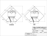
1.2.6 Plumbing Diagram and Tubing Lengths
Figure 1 shows the user-replaceable tubing on the analyzer and Table 1
describes the terminal end sizes of each tube. The tubing is 0.030 inch ID
Tefzel. The small diameter allows for low-volume, high-flow rates. The higher
flow rate, along with properly applied sample conditioning, prevents the tubing
from plugging.
General information for replacing the tubing is presented in the APA 6000
Installation and Maintenance Manual (Cat. No. 62005-18).
CAUTION
To familiarize yourself with
handling precautions, dangers
and emergency procedures,
always review the Material Safety
Data Sheets prior to handling
containers, reservoirs, and
delivery systems that contain
chemical reagents and standards.
Protective eye wear is always
recommended when contact with
chemicals is possible.
PRUDENCE
Pour se familiariser avec les précautions à prendre lors de la manipulation, les
dangers et les procédures d'urgence, toujours lire les Fiches de Données de
Sécurité des Produits avant de manipuler les récipients, les réservoirs et les
systèmes de distribution contenant les réactifs chimiques et les solutions
étalons. Il est toujours recommandé de porter des lunettes de protection
lorsqu'un contact avec les produits chimiques est possible.
CUIDADO
Para familiarizarse con las precauciones de manipulación, los peligros y los
procedimientos de emergencia, siempre estudie las Hojas de Datos de
Seguridad de los Materiales antes de manipular recipientes, depósitos y
sistemas de entrega que contengan reactivos y patrones químicos. Siempre se
recomienda el uso de protectores oculares cuando sea posible el contacto con
productos químicos.

Section 1
Page 8
General Description
6202918overview.fm
VORISCHT
Es wird dringend empfohlen, die Sicherheitsdatenblätter vor der Handhabung
von Behältern, Tanks und Zufuhrsystemen, die chemische Reagenzien und
Standardsubstanzen enthalten, aufmerksam durchzulesen, damit Sie sich mit
den beim Umgang mit diesen Chemikalien notwendigen Vorsichtsmaßnahmen,
Risiken und Notfallschutzmaßnahmen vertraut machen, Es wird empfohlen, in
allen Situationen, in denen mit einem Kontakt mit Chemikalien zu rechnen ist,
eine Schutzbrille zu tragen.
ATTENZIONE
Per familiarizzare con misure di precauzione di controllo manuale, con
procedure pericolose e di emergenza, rileggere sempre le schede di sicurezza
del materiale prima di maneggiare contenitori, imballaggi per spedizione che
contengono reagenti chimici e standards. Si consiglia di indossare sempre gli
occhiali protettivi quando è possibile un contatto con agenti chimici.
1.2.7 Vortex Sample Conditioning Block
The sample conditioning block consists of a 0.5 µm ceramic filter held within a
flow block. Unfiltered sample flows around the outside of the filter and serves
to continuously self-clean the filter element.
1.2.8 Copper Reagents
Calibration depends on the range chosen. The low range gives
optimal accuracy below 1 mg/L and the high range gives optimal accuracy
from 1–10 mg/L. Both use the same reagents, but require different
calibration standards.
The low range model uses the 0- and 1.0-mg/L standards as standard 1 and
standard 2, respectively. The high-range model uses the 0- and 10-mg/L
standards as standard 1 and standard 2, respectively. The low range
calibration is linear; the high range calibration forces the intercept through
zero and is a quadratic function.
• APA Copper Reagent 1 is an acetate buffer used to control the pH at
approximately 5.
• APA Copper Reagent 2 is an indicator. The indicator uses a cuprethol
reagent to chelate to copper and form a yellow color.
• APA Copper Standards 1 and 2 are used for calibration. Standard 1 is
a0mg/L as Cu
2+
solution. Standard 2 is a 1.0 mg/L as Cu
2+
solution for
the low range instrument and a 10.0 mg/L Cu
2+
solution for the high
range instrument.
• The fifth reagent, APA Phosphoric Acid Wash, cleans the system during
the Prime and Instrument Clean functions.This weak phosphoric acid
solution assures the system stays free of metal precipitate buildup.

Section 1
Page 9
6202918overview.fm General Description
Figure 1 Plumbing Diagram for a Copper APA Analyzer
Table 1 Replacement Tubing Lengths for Figure 1
Item Description Length From... To...
1 Tefzel tubing, 0.03 ID x 0.062 OD 7.3 in. (18.5 cm) Port 1 Colorimeter in
2 Tefzel tubing, 0.03 ID x0.062 OD 24 in. (60 cm) Port 2 Sample 1
3 Blank port — — —
4 Blank port — — —
5 Tefzel tubing, 0.03 ID x 0.062 OD 57 in. (145 cm) Port 5 Standard 1
6 Tefzel tubing, 0.03 ID x 0.062 OD 61 in. (152.5 cm) Port 6 Standard 2
7 Tefzel tubing, 0.03 ID x 0.062 OD 34.5 in. (87.5 cm) Port 7 Waste
8 Tefzel tubing, 0.03 ID x 0.062 OD 57 in. (145 cm) Port 8 Reagent 1
9 Tefzel tubing, 0.03 ID x 0.062 OD 60 in. (152.5 cm) Port 9 Reagent 2
10 Tefzel tubing, 0.03 ID x 0.062 OD 8.3 in. (21 cm) Port 10 Mixer module in
11 Tefzel tubing, 0.03 ID x 0.062 OD 27.5 in. (70 cm) Mixer module out Mixer drain
12 Tefzel tubing, 0.03 ID x 0.062 OD 7 in. (17.5 cm) Two-way NC Wash Solution
13 Tefzel tubing, 0.03 ID x 0.062 OD 6 in. (16 cm) Two-way out Autoburette bottom
14 Tefzel tubing, 0.03 ID x 0.062 OD 26 in. (66 cm) Back pressure out Colorimeter drain
15 Holding Coil 8.3 in. (21 cm) Center port Autoburette top

Page 10
Theory of Operation
6202918theory.fm
Section 2 Theory of Operation
The APA 6000™ analyzer is designed to provide reproducible results through
consistent solution handling. Every step in an analysis is performed the same
way each time, ensuring accurate results. Accuracy can be verified and
established by measuring grab samples with a known copper concentration.
The analyzer works as follows:
1. The instrument aspirates sample into the holding coil.
2. Appropriate reagents are aspirated.
3. Sample and reagents are premixed in a mixing chamber.
4. The sample-reagent mixture is dispensed into the reaction coil, then into
the detector.
5. The mixture flows through the detector, where color is measured.
2.1 Method of Analysis
The analyzer determines the copper concentration in a sample stream using
the cuprethol method. Copper in the sample combines with the indicator
reagent to form a yellow-colored chelant, which is directly proportional to the
copper concentration. The buffer reagent ensures the optimal pH conditions
for the cuprethol reaction.
The APA 6000 requires calibration to ensure instrument specifications are
met. The analyzer monitors the response, and that response must be within a
given range to assure the reagents are functional and the proper standards
are in use. Consecutive runs must be repeatable. Repeatable runs increase
confidence that the right value is used from the calibration. If these two criteria
are not met, an error will result and the analyzer will not use the values
obtained from the “failed” calibration.
The measurement cycle performs a colorimetric analysis to make an accurate
measurement of copper in the sample stream. During normal operation the
10-port Rotary Valve rotates to various positions to move sample and
reagents through the analyzer. Table 2 lists the port numbers and their
function.
Table 2 Port Functions For Copper Analysis
Port # Function Port # Function
1 Detector 6 Standard 2
2 Sample 1 7 Waste
3 Sample 2 8 Reagent 1
4 Not used 9 Reagent 2
5 Standard 1 10 Mixer

Section 2
Page 11
6202918theory.fm Reagent and Standard Consumption
2.2 Reagent and Standard Consumption
The rate of reagent use depends on many factors, including the number of
times the instrument cycles, calibration frequency, and the number of clean
cycles. Table 3 provides the approximate volume (in mL) of the reagents
consumed with each type of function per cycle.
Table 3 Reagent Consumption in mL
Solution Measurement Calibration Cleaning
Sample 4.6 0 0
Reagent 1 0.06 0.36 0
Reagent 2 0.06 0.36 0
Standard 1 0 11.7 0
Standard 2 0 11.7 0
Cleaning Solution 0.09 0.6 9.6

Page 12
Parameter Specific Menu Functions
6202918menu.fm
Section 3 Parameter Specific Menu Functions
3.1 Calibration History
This option allows you to review past calibration data.
1. Press the MENU key to start from the Main Menu.
2. Select Sensor Menu and press ENTER.
3. Select the sensor by name and press ENTER.
4. Select Calibration and press ENTER.
5. Select Cal History and press ENTER.
6. A pop-up box will appear with the calibration date and time of the seven
most recent calibrations. Select Review Next Cal to step through the
calibration history screens. After the last calibration, press ENTER to
return to the previous menu. To exit the Cal History Menu, press EXIT.
Data displayed for the seven most recent calibrations include the
concentration (in ppm) of the 0.2 (low range) or 2 (high range) standard in the
first column and the concentration (in ppm) of the 0.8 (low range) or 8 (high
range) standard in the second column. The values are based on the previous
calibration curve applied to the standards on the current calibration. If the
previous calibration was a default calibration (the first calibration) or if
conditions have changed (for example, if new reagents and standards have
been introduced), then a shift is expected.
3.2 Measurement Options
The analyzer allows several options for the display of concentration values.
The units can be changed. Available options are ppm, ppb, mg/L, and µg/L.
Note: If a Digital Display Module (DDM) is used, select SENSOR to DISPLAY in the
Network Menu to set the output of the DDM.
Important Note: Changing the displayed units will cause the stored data for the
AquaTrend channel on which the units were changed to be erased.

Page 13
6202918script.fm Sequence of Instrument Events
Section 4 Sequence of Instrument Events
Table 4 Initialization
Valve Position Volume (µL) Autoburette Action
Mixer 600 Aspirate
Waste 600 Dispense
Mixer 600 Aspirate
Waste 600 Dispense
Sample 1000 Aspirate
Between ports 500 Aspirate
Detector 1500 Dispense
Between ports 1000 Aspirate
Waste 1600 Dispense
Table 5 Measurement Mode
Valve Position Volume (µL) Autoburette Action
Sample 250 Aspirate
Between ports 20 Aspirate
Mixer 200 Aspirate
Waste 470 Dispense
Sample 1410 Aspirate
Waste 0 Depressurize
Between ports 90 Aspirate
Detector 400 Dispense
Mixer 1000 Dispense
Mixer 800 Aspirate
Mixer 220 Aspirate
Waste 1120 Dispense
Sample 1440 Aspirate
Mixer 0 Depressurize
Reagent 2 60 Aspirate
Mixer 680 Dispense
Mixer 0 Depressurize
Reagent 1 60 Aspirate
Mixer 320 Dispense
Mixer 850 Aspirate
Waste 50 Dispense
Detector 1360 Dispense

Section 4
Page 14
Sequence of Instrument Events
6202918script.fm
Table 6 Cleaning
Valve Position Volume (µL) Autoburette Action
Between ports 1600 Aspirate
Waste 1600 Dispense
Between ports 1600 Aspirate
Mixer 1600 Dispense
Between ports 1600 Aspirate
Sample 1600 Dispense
Between ports 1600 Aspirate
Waste 1600 Dispense
Mixer 1600 Aspirate
Sample 1600 Dispense
Sample 1600 Aspirate
Waste 1600 Dispense
Sample 1600 Aspirate
Waste 1600 Dispense
Sample 1600 Aspirate
Waste 1600 Dispense
Sample 1600 Aspirate
Waste 1600 Dispense
Mixer 1600 Aspirate
Waste 1600 Dispense
Table 7 Prime
Valve Position Volume (µL) Autoburette Action
Reagent 1 800 Aspirate
Waste 800 Dispense
Reagent 1 400 Aspirate
Waste 400 Dispense
Reagent 2 800 Aspirate
Waste 800 Dispense
Reagent 2 400 Aspirate
Waste 400 Dispense
Between ports 1600 Aspirate
Waste 1600 Dispense
Standard 2 1600 Aspirate
Waste 1600 Dispense
Standard 1 1600 Aspirate
Waste 1600 Dispense
Between ports 1600 Aspirate
Waste 1600 Dispense
Between ports 1600 Aspirate
Waste 1600 Dispense

Section 4
Page 15
6202918script.fm Sequence of Instrument Events
Table 8 Calibration
Valve Position Volume (µL) Autoburette Action
Std1
Sample 250 Aspirate
Between ports 20 Aspirate
Mixer 200 Aspirate
Waste 470 Dispense
Standard 1 1510 Aspirate
Between ports 90 Aspirate
Detector 500 Dispense
Standard 2 152 Aspirate
Mixer 1000 Dispense
Mixer 800 Aspirate
Mixer 280 Aspirate
Waste 1332 Dispense
Standard 1 1328 Aspirate
Standard 2 112 Aspirate
Mixer 680 Dispense
Waste 760 Dispense
Mixer 600 Aspirate
Mixer 50 Aspirate
Standard 1 638 Aspirate
Standard 2 152 Aspirate
Mixer 790 Dispense
Mixer 790 Aspirate
Reagent 2 60 Aspirate
Mixer 680 Dispense
Reagent 1 60 Aspirate
Mixer 290 Dispense
Mixer 850 Aspirate
Waste 50 Dispense
Detector 1300 Dispense
Detector 90 Dispense

Section 4
Page 16
Sequence of Instrument Events
6202918script.fm
STD2
Sample 250 Aspirate
Between ports 20 Aspirate
Mixer 200 Aspirate
Waste 470 Dispense
Standard 2 1510 Aspirate
Between ports 90 Aspirate
Detector 500 Dispense
Standard 1 152 Aspirate
Mixer 1000 Dispense
Mixer 800 Aspirate
Mixer 280 Aspirate
Waste 1332 Dispense
Standard 2 1328 Aspirate
Standard 1 112 Aspirate
Mixer 680 Dispense
Waste 760 Dispense
Mixer 600 Aspirate
Mixer 50 Aspirate
Standard 2 638 Aspirate
Standard 1 152 Aspirate
Mixer 790 Dispense
Mixer 790 Aspirate
Reagent 2 60 Aspirate
Mixer 680 Dispense
Reagent 1 60 Aspirate
Mixer 290 Dispense
Mixer 850 Aspirate
Waste 50 Dispense
Detector 1300 Dispense
Detector 90 Dispense
Table 8 Calibration (continued)
Valve Position Volume (µL) Autoburette Action

Page 17
6202918bench.fm Bench Comparison Testing
Section 5 Bench Comparison Testing
5.1 Comparable Bench Methods
The procedure presented here uses the APA 6000™ Copper Reagents to
create a correlation between the analyzer and a method performed in the
laboratory.
Other copper procedures may be used to create that correlation. Other
methods presented in Standard Methods for the Examination of Water and
Wastewater should provide comparable results.
5.2 Bench Method Procedure
Calibration is necessary before testing samples for copper. Calibrating with
Standard 1 (0.0 mg/L) and Standard 2 (low range) (1.0 mg/L) determines the
blank and slope value.
Use the following hints to make calibration more efficient:
• Take all measurements at 25 °C for best accuracy.
• Use polyethylene bottles to store standards.
• If measuring high concentration samples (>5 mg/L Cu
2+
), verify the
calibration line using the Standard 2 (high range) 10.0 mg/L.
Copper Calibration Procedure
1. Prepare the Zero
Standard and Standard 1.
2. Using a volumetric
pipet, transfer 5 mL of
APA Copper Reagent 2
(indicator) into a 100-mL
volumetric flask. Add about
75 mL of Zero Standard
and mix.
3. Add 5 mL of APA
Copper Reagent 1 (buffer)
to the same flask. Fill the
volumetric flask to the
mark with the Zero
Standard. Label as
“0 ppm standard”.
4. Invert the flask at least
7 times to mix.
Prepare standards.

Page 18
Bench Method Procedure
6202918bench.fm
Section 5
5. Repeat Steps 2–4,
using the APA Standard 2
(low range) 1.0 mg/L
in Step 2 and 3 in place of
the Zero Standard. Label
as “1 ppm standard”.
6. Using a 1-cm sample
cell and a Hach DR/4000*
Spectrophotometer,
zero at 440 nm with
deionized water.
*High concentration samples
and standards will have an
absorbance >1.5. Use a DR/4000
for accurate measurements at
these conditions.
7. Within 10 minutes of
adding reagents, transfer
3 mL of the 0 ppm
standard into a 1-cm cell.
Measure the absorbance
at 440 nm.
Note: For best accuracy,
rinse the cell three times
with the standard before
measurement.
8. Record the value.
9. Repeat Steps 7–8,
using the 1-ppm standard.
10. The blank is the
absorbance value of the
0-ppm standard. The slope
is the difference between
the absorbance values of
the 1-ppm standard and
the 0-ppm standard.
Repeat Steps 2–4 for
second standard.
440 nm
Repeat Steps 7 and 8.

Section 5
Page 19
6202918bench.fm Determining Copper Concentration in Samples
5.3 Determining Copper Concentration in Samples
Testing Samples
1. Using a volumetric
pipet, transfer 5 mL of
APA Copper Reagent 2
(indicator) into a 100-mL
volumetric flask. Add
approximately 75 mL
of sample to the flask
and mix.
2. Add 5mLof APA
Copper Reagent 1 (buffer)
to the same flask. Fill to
the mark with sample.
Invert the flask at least
seven times to mix.
3. Within 10 minutes of
adding reagents, transfer
3 mL of sample into a 1-cm
cell. Measure the
absorbance at 440 nm.
4. Calculate the total
copper concentration in
the sample using the
following equations.
440 nm
Blank Absorbance of 0 ppm standard=
Slope Abs. of 1 ppm standard – Blank absorbance=
Copper (ppm)
Sample Abs. Blank Abs.–
Slope
--------------------------------------------------------------------
=

Page 20
Replacement Parts
6202918parts.fm
Section 6 Replacement Parts
Reagents and Standards
Description Unit Cat. No.
APA 6000™ Copper Reagent 1 ................................................................................................... 1 L..........27559-53
APA 6000™ Copper Reagent 2 ................................................................................................... 1 L..........27560-53
APA 6000™ Copper Standard 1, 0.0 mg/L .................................................................................. 1 L..........27562-53
APA 6000™Copper Standard 2, low range, 1.0 mg/L.................................................................. 1 L..........27563-53
APA 6000™ Copper Standard 2, high range, 10.0 mg/L ............................................................. 1 L..........27564-53
APA 6000™ Cleaning Solution..................................................................................................... 1 L..........26964-53
Required Reagents for the Bench Procedure
APA 6000™ Copper Standard 1, 0 mg/L as Cu
2+
........................................90 mL..................... 1 L..........27562-53
APA 6000™ Copper Standard 2 (low range), 1 mg/L as Cu
2+
..................... 90 mL .................... 1 L..........27563-53
APA 6000™ Copper Standard 2 (high range), see Optional Reagents and Apparatus
APA 6000™ Copper Reagent 1 ...................................................................15 mL..................... 1 L..........27559-53
APA 6000™ Copper Reagent 2 ...................................................................15 mL..................... 1 L..........27560-53
Water, deionized ..........................................................................................10 mL..................... 4 L..............272-56
Required Apparatus for the Bench Procedure
DR/4000 Spectrophotometer, UV-Vis...............................................................1.......................each..........48000-00
Flask, volumetric, 100 mL, Class A..................................................................3.......................each..........14574-42
Pipet, disposable, transfer................................................................................1..................200/box..........21234-00
Pipet, volumetric, 5.00 mL, Class A.................................................................2.......................each..........14515-37
Pipet bulb, 3-valve............................................................................................1.......................each..........12189-00
Wash Bottle, 500 mL........................................................................................1.......................each..............620-11
Replacement Parts
Mixer Module Assembly, APA 6000, 1-mL .................................................................................each..........51021-00
Colorimeter Assembly, APA 6000...............................................................................................each..........62058-02
Colorimeter Module, 440 nm......................................................................................................each..........62060-02
Optional Reagents and Apparatus
APA 6000™ Copper Standard 2 (high range), 10 mg/L as Cu
2+
................................................. 1 L..........27564-53
Bottles, polyethylene, 60 mL, storage .....................................................................................12/pkg..........20870-71
Kimwipes
®
, 11 x 22 cm (4.5 x 8.5 inches) ............................................................................280/box..........20970-00
Syringe, 3 cc, Luer Lock.............................................................................................................each..........43213-00
For general APA 6000 Parts and Accessories, please see the APA 6000
Process Analyzer Installation and Maintenance Manual, Cat. No. 62005-18.
/