
www.ventiladoreshunter.com.br
MD518-01 • 10/06/14 • © Hunter Fan Company
ENGLISH

Important Instructions: Keep Instructions for future use

1
www.hunterfan.com.br
MD518-01 • 10/06/14 • © Hunter Fan Compan
PAG E
4
30 inches
7 feet
PAG E
2
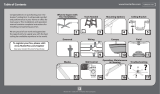
What to Expect with
Your Installation
Ceiling Bracket
Ladder
PAG E
3
Tools Needed
Table of Contents
Mounting Options
PAG E
6
PAG E
9
Wiring CanopyDownrod
PAG E
10
PAG E
18
Maintenance &
Cleaning
Troubleshooting
?
?
?
PAG E
19
Warranty Statement
PAG E
17
PAG E
12
PAG E
13
Switch Housing Light Kit
Blades
PAG E
11
PAG E
4
Congratulations on purchasing your new Hunter®
ceiling fan! It will provide comfort and performance
in your home or ofce for many years. This installation
and operation manual contains complete instructions
for installing and operating your fan.
We are proud of our work and appreciate the
opportunity to supply you with the best ceiling fan
available anywhere in the world.
Wall Control
PAG E
15

www.hunterfan.com.br
2
MD518-01 • 10/06/14 • © Hunter Fan Company
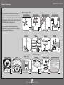
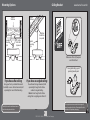
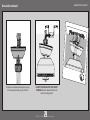
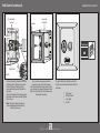
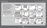
What to Expect with Your Installation
w.1 - To reduce the risk of re, electrical shock, or personal injury,
mount fan directly from building structure and/or an outlet
box marked acceptable for fan support of 31.8 kg and use the
mounting screws provided with the outlet box.
w.2 - To avoid possible electrical shock, before installing or
servicing your fan, disconnect the power by turning off the circuit
breakers to the outlet box and associated wall switch location. If
you cannot lock the circuit breakers in the off position, securely
fasten a prominent warning device, such as a tag, to the service
panel.
w.3 - To reduce the risk of re, electrical shock, or motor damage,
use only Hunter Solid State Speed Controls.
w.4 - To reduce the risk of personal injury, do not bend the blade
brackets when installing the blade brackets, balancing the blades, or
cleaning the fan. Do not insert foreign objects in between rotating fan
blades.
w.5 - This appliance is not intended for use by persons (including
children) with reduced physical, sensory or mental capabilities, or
people with a lack of experience and knowledge, unless they have
received instructions regarding the use of the device or under the
supervision of a person responsible for their safety.
w.6 - It is recommended that children be supervised to ensure that
they are not using the appliance improperly
c.1 - All wiring must be in accordance with national and local
electrical codes. If you are unfamiliar with wiring, use a qualied
electrician.
c.2 - Use only Hunter replacement parts.
You may need a
friend to help you.
Check box to see
fan weight
Assess location
0,50 meters
from blade tip to
nearest wall or
obstruction
2,3 meters
from bottom
edge of blade to
the oor
Know your wiring
If you are unfamiliar
with wiring, use a
qualied electrician.
WARNINGS
CAUTIONS
Must be able to
secure the fan to
building structure or
fan-rated outlet box.
Do not use a plastic
outlet box.
Select a downrod length
1
2
3
Standard Downrod
for ceilings 2,4 -3 meters high
Shorter Downrod
for fans installed close to ceiling
Longer Downrod
for ceilings 3 meters or higher
Use ONLY Hunter
Ceiling Fan branded
accessory light kits.

www.hunterfan.com.br
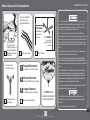
Tools Needed
Ladder
Pliers Wire Strippers
Screwdrivers
Power Drill
(optional)
3.5 mm Drill
Bit (optional)
8 mm Drill Bit
(optional)
If mounting to a support structure, you
will also need these tools.
Hammer
(optional)
3
MD518-01 • 10/06/14 • © Hunter Fan Company

www.hunterfan.com.br
Hang your fan by a standard downrod
(included) or use a shorter downrod (sold
separately) for Low-Prole Mounting.
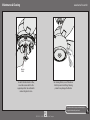
Mounting Options Ceiling Bracket
Note: Do not hang the fan from a
ceiling that is angled greater than 34°.
Support
Structure
Ceiling
Outlet Box
(required)
Angled
Mounting
Style
Standard
Mounting
Style
Support
Structure
Ceiling
Outlet Box
(required)
Carefully choose the installation location
that allows for optimal air ow.
The support structure must be able to support 5
times the weight of the fan. The weight of the fan is
located on the product packaging.
You will need a longer downrod (sold
separately) to hang the fan from a
vaulted or angled ceiling.
If you have a at ceiling: If you have an angled ceiling:
Make sure all four (4) bumpers
are still attached.
For angled ceilings, point
opening toward peak.
OFF
Turn Power
4
MD518-01 • 10/06/14 • © Hunter Fan Company

5
www.hunterfan.com.br
MD518-01 • 10/06/14 • © Hunter Fan Compan
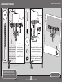
Ceiling Bracket (continued)
Refer to warning w.1 on pg. 2
To avoid possible electrical shock, before
installing your fan, disconnect the power by
turning off the circuit breakers to the outlet
box associated with the wall switch location.
Use wood screws
(included) when securing
to support structure with
approved electrical outlet
box. Drill 3.5 mm pilot
holes in support structure
to aid in securing ceiling
bracket with hardware
found in the hardware
bag.
Use machine screws
(provided with outlet
box) when securing to
existing ceiling fan-rated
outlet box. Make sure
it is securely installed
and is acceptable for fan
support of 31.8 kg or less.
Note: Do not mount ceiling fan
to a plastic outlet box.
Use concrete anchors (included)
when securing to support structure
with approved outlet box in a concrete
ceiling. Drill 8 mm pilot holes in
support structure. Hammer the M6
expansion anchors into the holes until
the ends are ush with the ceiling.
Install the washer, isolator, and nut
found in the hardware bag to
the expansion anchors.

6
www.hunterfan.com.br
MD518-01 • 10/06/14 • © Hunter Fan Compan
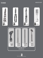
Downrod
Slide
Slide
1 2 3 4 5
678910
Sold Separately
Longer
Downrod
for angled
ceilings or
ceilings 3 m or
higher
Shorter
Downrod
for fans installed
close to ceiling
Standard
Downrod
for ceilings 2,4-3 m
high
Option 1Option 2
Option 3
skip to next page
If you need a different downrod length follow these steps:
Steps 1-5 to remove standard downrod pipe
Steps 6-10 to reassemble with new pipe
Included
(pre-assembled)
Sold Separately

7
www.hunterfan.com.br
MD518-01 • 10/06/14 • © Hunter Fan Compan
20 cm
1 cm
C
U
T
&
S
T
R
I
P
(not to scale)
Remove the pre-installed
setscrew so that the downrod
can be inserted.
Hand tighten the downrod (at
least 4-5 full turns) until it stops.
The wires can be cut,
but leave at least 20 cm
extending from the top of
the downrod.
Downrod (continued)
Tighten the setscrew
with pliers. DO NOT
HAND TIGHTEN.
If the setscrew is not tightened
securely, the fan may fall.
K
E
E
P
!
20 cm 1 cm

8
www.hunterfan.com.br
MD518-01 • 10/06/14 • © Hunter Fan Compan
Downrod (continued)
DO NOT PICK THE FAN UP BY THE CANOPY
OR WIRES. Place the downrod ball into the
slot in the ceiling bracket.
Put the wires and downrod through the canopy.
Let the canopy sit loosely on top of the fan.

9
www.hunterfan.com.br
MD518-01 • 10/06/14 • © Hunter Fan Compan
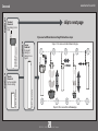
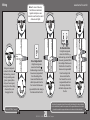
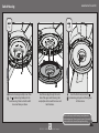
Wiring
Note: To connect the wires,
hold the bare metal leads
together and place a wire
connector over them, then twist
clockwise until tight.
Turn the splices upward and push them carefully back through the hanger bracket
into the outlet box. Spread the wires apart, with the grounded wires on one side of
the outlet box and the ungrounded wires on the other side of the outlet box.
Refer to CAUTION c.1 on pg. 2
F
R
O
M
F
A
N
Blue
Brown
(Grounded)
Note: To connect the wires,
hold the bare metal leads
together and place a wire
connector over them, then twist
clockwise until tight.
Using the orange wire
connectors from the
hardware bag, connect the
brown wire (ungrounded)
from the ceiling to the
brown and the black with
white stripe wires from the
fan. Connect the blue wire
(grounded) from the ceiling to
the blue wire from the fan.
Using the orange wire
connectors from the
hardware bag, connect the
blue wire (grounded) from
the ceiling to the blue wire
from the fan. Connect the
brown wire (ungrounded)
from the ceiling to the
brown wire from the
fan. Connect the second
(ungrounded) wire from
the ceiling to the black
with white stripe wire from
the fan.
F
R
O
M
F
A
N
Blue
(Ungrounded)
Brown
Black with white stripe
(Grounded)
F
R
O
M
C
E
I
L
I
N
G
(Ungrounded)
For Dual Switches
For a Single Switch
F
R
O
M
C
E
I
L
I
N
G
Bl
a
c
k
w
i
t
h
White Stripe
(Ungrounded)
F
R
O
M
F
A
N
F
R
O
M
C
E
I
L
I
N
G
B
R
A
C
K
E
T
Using an orange wire
connector from the
hardware bag, connect
the 4 grounding wires
(green, green/yellow
stripe, or bare copper)
coming from the ceiling,
downrod, fan, and
hanging bracket.
(Grounding)
Green/Yellow
Stripe
Green/Yellow
Stripe
F
R
O
M
C
E
I
L
I
N
G

10
www.hunterfan.com.br
MD518-01 • 10/06/14 • © Hunter Fan Compan
Canopy
Lift the canopy into place so that
the screw holes are aligned.
Position the canopy so that, when
lifted into place, the canopy ts into
the hanging bracket as shown.
Insert the two canopy screws
found in the hardware bag.
Note: Fan style may vary.
Screw
Holes

11
www.hunterfan.com.br
MD518-01 • 10/06/14 • © Hunter Fan Compan
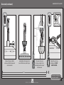
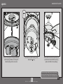
Blades
Your blades are shielded with Dust Armor® which
is a nanotechnology coating that repels dust. For
cleaning the fan, use soft brushes or cloths to prevent
scratching. Cleaning agents may damage the nishes.
Lightly attach the blade irons to the motor
with the blade iron armature screws, found
in the hardware bag. Then, securely
tighten after both screws are attached.
Attach each blade to a blade iron using three
blade washers and three blade assembly
screws, found in the hardware bag.

12
www.hunterfan.com.br
MD518-01 • 10/06/14 • © Hunter Fan Compan
Feed the wire plug through the center
hole of the upper switch housing, then
wrap keyhole slots around the screws and
twist clockwise.
Screw two housing assembly screws from
the hardware bag halfway into the
motor housing. It does not matter which
two screw holes you choose.
Insert the third screw, found in the
hardware bag, into place and then tighten
all three screws.
Make sure the upper switch housing is securely attached
to the mounting plate. Failure to properly secure all 3 assembly
screws could result in the switch housing xture falling.
Switch Housing

13
www.hunterfan.com.br
MD518-01 • 10/06/14 • © Hunter Fan Compan
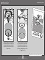
Light Kit
Make sure the lower switch housing is securely attached
to the upper switch housing. Failure to properly secure all
three assembly screws could result in the light xture falling.
Connect the plugs from the upper and lower
switch housings. Make sure to line up the
colored markings on the connectors.
Install the three switch housing screws
found in the bag.
Install a 20W CFL bulb (sold separately) into
each of the E27 sockets. When necessary,
replace with bulbs of same wattage.
Bulb

14
www.hunterfan.com.br
MD518-01 • 10/06/14 • © Hunter Fan Compan
Light Kit (continued)
CONGRATULATIONS!
YOU’RE DONE!
Note: Glass shade style and number of lights may vary.
To install the outer glass, raise the outer
glass to the light xture. Align the holes
in the outer glass with the holes in the
upper switch housing brackets. Securely
tighten the included thumbscrews, found
in the hardware bag.
Shade
Thumbscrew
Carefully lift the glass so the threaded rod
on the light xture goes through the hole
in the globe. With the other hand, install
the nial cap onto the threaded rod and
tighten securely.
Glass
Finial Cap
Metal
Plate

15
www.hunterfan.com.br
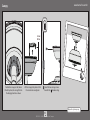
MD518-01 • 10/06/14 • © Hunter Fan Compan
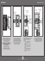
Press the rotary switch terminal
into the hole in the faceplate as
shown with screw terminals facing
away from the light switch. Install
the knob onto the switch after it is
pressed into the faceplate.
Attach a jumper wire (not included)
from terminal 2 of the rotary switch
to the center terminal of the rocker
switch. Tighten the set screws.
Connect the wires from the capacitor
to the rotary switch terminal as
follows:
• Grey from the capacitor to
terminal 3. Tighten the set
screw.
• Brown from the capacitor to
terminal 1. Tighten the set
screw.
• Green from the capacitor to
terminal 4. Tighten the set
screw.
To install the wall control, you must
first remove the faceplate and switch
assembly from the existing wall
control, if you have one.
Save the screws you removed from
the faceplate to use with the new
included faceplate.
Wall Control
4
1
2
3
Rotary Switch
Terminal
Rotary Switch
Terminal
Capacitor
Knob
4
1
2
3
Rotary Switch
Terminal
Rocker
Switch
Note: A power disconnect
switch should be installed in
conjunction with the wall control.

16
www.hunterfan.com.br
MD518-01 • 10/06/14 • © Hunter Fan Compan
Wall Control (continued)
The light switch turns the light on and off.
The fan control controls the speed of the fan
as follows:
High Speed
Medium Speed
Low Speed
Fan Off
3
2
1
0
Be sure no bare wire is exposed at the
connection points. Attach the faceplate
assembly to the wall box using the two screws
you saved from the original faceplate intalled
with your wall switch. Press the faceplate onto
the faceplate assembly.
Faceplate
Faceplate
Assembly
• Connect the wire for the fan to the rotary
switch terminal 3. Tighten the set screw.
• Connect the wire to the light to the
rocker switch top terminal. Tighten the
set screw.
• Connect the wire from the supply main to
the rocker switch center terminal. Tighten
the set screw.
Fan Wire
Supply Main
Light Wire
4
1
2
3
Note: The rocker switch terminal may
have an additional bottom terminal
that will not be used.
ON
Turn Power
Rocker Switch
Terminal

17
www.hunterfan.com.br
MD518-01 • 10/06/14 • © Hunter Fan Compan
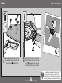
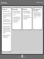
Maintenance & Cleaning
To switch the direction of air ow,
move the reverse switch to the
opposite position. You will need to
remove the glass to do so.
For cleaning the fan, use soft brushes or
cloths to prevent scratching. Cleaning
products may damage the nishes.
To avoid accident or injury, avoid touching the
ceiling fan blades with your hands.
Reverse
Switch

18
www.hunterfan.com.br
MD518-01 • 10/06/14 • © Hunter Fan Compan
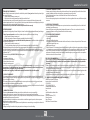
Troubleshooting
Excessive wobbling
• Tighten all of the blade and
blade iron screws until they
are snug.
• Turn the power off, support
the fan carefully, and check
that the hanger ball is
properly seated.
Noisy Operation
• Tighten the blade and blade
iron screws until they are snug.
• Check to see if any of the
blades are cracked. If so, replace
all of the blades.
Fan doesn’t work
• Make sure power switch is on.
• Push the motor reversing switch
rmly left or right to ensure that
it is engaged.
• Check the circuit breaker to
ensure the power is turned on.
• Make sure the blades spin freely.
• Turn off power from the circuit
breaker, then loosen the canopy
and check all the connections
according to the wiring diagram
on page 9.
• Check the plug connection in
the switch housing.
Lights dim when turned on or
do not turn on at all.
• Make sure the wattage of the
light bulbs installed matches
the specications on the light
sockets.
Page is loading ...
-
 1
1
-
 2
2
-
 3
3
-
 4
4
-
 5
5
-
 6
6
-
 7
7
-
 8
8
-
 9
9
-
 10
10
-
 11
11
-
 12
12
-
 13
13
-
 14
14
-
 15
15
-
 16
16
-
 17
17
-
 18
18
-
 19
19
-
 20
20
-
 21
21


Hunter Fan 50080 Owner's manual
- Type
- Owner's manual
Ask a question and I''ll find the answer in the document
Finding information in a document is now easier with AI
Related papers
-
 Hunter Fan 50820 Owner's manual
-
 Hunter Fan 50850 Owner's manual
-
 Hunter Fan 50857 Owner's manual
-
 Hunter Fan 50016 Owner's manual
-
 Hunter Fan 50065 Owner's manual
-
 Hunter Fan 50027 Owner's manual
-
 Hunter Fan 50052 Owner's manual
-
 Hunter Fan 50889 Owner's manual
-
Hunter Fan 50086 Owner's manual
-
 Hunter Fan 50816 Owner's manual


Other documents
-
AURORA MOUNTS AFC-CP User manual
-
Crystorama MAR-A8031-PN User manual
-
Crystorama MAR-A8031-MK User manual
-
Crystorama MAR-A8031-AG User manual
-
Filament Design CLI-JB-037371 Installation guide
-
Hunter Installation guide
-
 Hunter Fan Company 59136 User manual
-
-
Hunter Fan Company 52" Builder Elite User manual
-
 Hunter Fan Company 53243 User manual

