
Model No. 831.215000
Sedal No.
Write the sedaUnumber in the
space above for reference.
SedaU
Number
DecaU
, Assembly
, Operation
. Maintenance
, Part List and Drawing
Read aH precautions and instruco
tions in this manual before using
this equipment. Keep this manual
for future reference.
User's Manua
Sears, Roebuck and Co., Hoffman Estates, IL 60179

TABLE OF CONTENTS
iMPORTANT PRECAUTIONS ................................................................ 2
BEFORE YOU BEGIN ...................................................................... 3
ASSEMBLY ............................................................................... 4
HOW TO OPERATE THE EXERCISE CYCLE .................................................... 8
MAINTENANCE AND TROUBLESHOOTING .................................................... 11
CONDiTiONiNG GUiDELiNES ............................................................... 12
PART LiST .............................................................................. 14
EXPLODED DRAWING .................................................................... 15
ORDERING REPLACEMENT PARTS .................................................. Back Cover
FULL 90 DAY WARRANTY .......................................................... Back Cover
mMPORTANT PRECAUTmONS
A WARNING: Toreducether_skofso.cue_njury,readthefo,owingimportant precau-
tionsbefore using the exercise cycle.
Read aH instructions in this manual and aH 8. Wear appropriate clothes when exercising; do
warnings on the exercise cycle before using not wear loose cJothes that could become
the exercise cycle. Use the exercise cycle onJy caught on the exercise cycle. Always wear
as described in this manual athJetic shoes for foot protection.
2. it is the responsibility of the owner to ensure
that aH users of the exercise cycle are ade=
quately informed of aH precautions.
3. The exercise cycle is intended for home use
onJy. Do not use the exercise cycle in
a commercial, rental, or institutional eetting.
,
Keep the exercise cycle indoors, away from
moisture and dust. Place the exercise cycle
on a leveJ surface, with a mat beneath it to
protect the floor or carpet. Make sure that
there is enough clearance around the exer-
cise cycle to mount, dismount, and use it.
6. Keep children under the age of !2 and pets
away L'rom the exercise cycle at aH times.
9. The pulse sensor is not a medicaJ device.
Various factors, including the user's move-
ment, may affect the accuracy of heart rate
readings. The pulse sensor isintended only
as an exercise aid in determining heart rate
trends in general
7. The exercise cycle should not be used by
persons weighing mote than 250 pounds.
10. Always keep your back straight when using
the exercise cycle; do not arch your back.
11. If you feel pain or dizziness while exercising,
stop immediately and cool down.
12. The exercise cycle does not have a freewheeJ;
the pedals will continue to move until the fly-
Inspect and properly tighten alJ parts reguJarly, wheel stops.
Replace any worn parts immediately.
13. The decal shown on page 3 has been placed
on the exercise cycle. If the decaJ is missing,
or if it is not legible, pJease call toil-free
1-866-699-3756 and order a free replacement
decal AppJy the decal in the Jocation shown.
;_ WARNING: Beforebeginningth_soranyexerc_eeprogram,consultyourphysician.Thie
is especially important for persons over the age of 35 or persons with pre-existing health problems.
Read aH instructions before using. Sears assumes no responsibility for personal injury or property
damage sustained by or through the use of this product.

BEFORE YOU BEGIN
CongratuUations for sebcting the new WESLO ®
PURSUF 330 exercise cycle, Cycling is one of the
most effective exercises for increasing cardiovascuUar
fitness, building endurance, and toning the body, The
PURSUF 330 exercise cycle offers a sebction of fea-
tures designed to bt you enjoy this heaUthfuUexercise
in the convenience and privacy of your home,
For your benefit, read this manual carefully before
you use the exercise cycle, ff you have questions
after reading this manual phase call 1-800-4-MY-
HOME ®(1-800-469-4663), To heUpus assist you,
phase note the product modeUnumber and sedaU
number before calling, The modeUnumber is
831,215000, The serial number can be found on a
decal attached to the exercise cycle (see the front
cover of this manual),
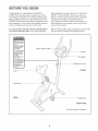
Before reading further, please familiarize yourself with
the parts that are labeled in the drawing below,
°Misuse oftMs machine
may result in serious
injury.
Read user's manuaU
prior to use and follow
air warnings and
instructions.
oDo not allow children
on or around machine
• Pedals continue to
spin when you stop
pedaling.
• Spinning pedaUs can
cause injury,.
Reduce pedamspeed
in a conttoOed manner
User weight must not
exceed 250 pounds.
.RepBace mabemif
damaged, iUlegibUe,or
removed.
Seat
Water Bottle
Seat Knob
REAR
Console
Handlebar
Resistance Knob
FRONT
PedaVStrap
RIGHT SIDE
*No water bottle is included
3

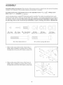
Assembly requires two persons. Hace aHparts of the exercise cycle in a cleared area and remove the packing
matedaUs, Do not dispose of the packing matedaUs until assemMy is compUeted,
Assembly requires the included tools and your own adjustable wrench _, Phillips screw-
driver _-11-- , and pliers
Use the drawings beUowto identify the small parts used for assemMy, The number in parenthesis beUoweach
drawing is the key number of the part, from the PART LUSTon page 14, The number following the key number is
the quantity needed for assemMy, Note: Some small parts may have been pre-assembled. If a part is not in
the parts bag, check to see if it has been pre-assemb[ed, if a part is missing, ca[[ toil-free 1-866-699-3756.
M4 x 5mm M4 x 16mm M8 x 15mm Button
Screw (14)-2 Screw (49)-5 Screw (34)-3
M8 x 58mm Button Bolt (6)-1
M8 Split M8 Nylon MIO Nylon
Washer (42)-8 Locknut (10)-5 Locknut (33)-4
/ '
MIO x 65mm Carriage Bolt (30)-4
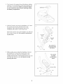
1, While another person lifts the front of the Frame (1)
slightly, attach a Stabilizer (2) with two MIO x 65mm
Carriage Bolts (30) and two MIO Nylon Locknuts (33),
2, While another person lifts the rear of the Frame (1)
slightly, attach a Stabilizer (2) with two MIO x 65mm
Carriage Bolts (30) and two MIO Nylon Locknuts (33),
3O
33
3O

3, TheConsoUe(16)requiresthreeAAbatteries;aUkaHne
batteriesarerecommended,Insertthreebatteriesinto
thebatterycompartment,Makesurethatthebatter-
iesareorientedasshownbythemarkingsinside
thebatterycompartment.
HoUdtheConsoUe(16)neartheHandUebar(15),Insert
theconsoUewireintotheindicatedhoUeinthe
HandUebar,Next,attachthegroundwiretothe
HandUebarwithanM4x 16mmScrew(49),
AttachtheConsoUe(16)totheHandUebar(15)withfour
M4x 16mmScrews(49),Becarefulto avoidpinch-
ingthewires.
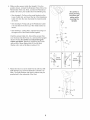
5, WhileanotherpersonhoUdstheHandUebar(15)near
theUpright(13),connecttheconsoUewiretothe
ExtensionWire(56),AttachtheHandUebartothe
UprightwiththreeM8x 15mmButtonScrews(34)and
threeM8SplitWashers(42),Becarefulto avoid
pinchingthewires.
/
/
16
\
\
\
\
\
Console \
Wire.
\
Hole Ground
Wire
Be carefuJ to
avoid pinching
the wires.
Be careful
\, '\
\ '\ to avoid
\
\, pinching the
\
wires.
34 J -I_ 13

6, While another person hoUdsthe Upright (13) in the
position shown, connect the Extension Wire (56) to the
Reed Switch Wire (43), Next, connect the Resistance
CaMe (19) to the Lower Cabb (45) in the following way:
See drawing A, Pull up on the metal bracket on the
Lower Cable (45), and insert the tip of the Resistance
Cable (19) into the wire clip inside the metal bracket
as shown,
See drawing B, FirmUypull up the Resistance CaMe
(19) and sfide it into the top of the metaUbracket as
shown,
See drawing C, Using pliers, squeeze the prongs on
the upper end of the metal bracket together,
Push the excess Cable (19, 45) and the excess Wire
(43, 56) down into the Frame (1), and insert the Upright
into the Frame, Be carefut to avoid pinching the
CabJes and Wires. Attach the Upright to the Frame
with an M8 x 58mm Button Bolt (6), an M8 Split
Washer (42), and an M8 Nylon Locknut (10),
7, Attach the Seat (12) to the Seat Post (5) with four M8
Split Washers (42) and four M8 Nylon Locknuts (10),
Note: The Split Washers and Nylon Locknuts may be
preattached to the underside of the Seat,
4--13
Be carefuJ to
avoid pinching
the wires and
cables while
inserting the
Upright.
-- 56
B
ii
iS/ 19
Metal_
Bracket
sS
_,' 10
/

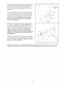
Orient the Seat Bushing (8) so that the indicated hoUein
the Seat Bushing is aligned with the indicated hoUein
the Frame (1), and press the Seat Bushing into the
Frame. Attach the Seat Bushing with two M4 x 5mm
Screws (14).
Insert the Seat Post (5) into the Frame (1), and align
one of the adjustment hoUesin the Seat Post with the
hoUein the Frame. Next, insert the Seat Knob (9) into
the Frame and the Seat Post, and turn the Seat Knob
clockwise until it is tight. Make sure that the Seat
Knob is inserted through one of the adjustment
hotes in the Seat Post.
Udentifythe Left PedaU(24), which is marked with an
"L." Using an adjustaMe wrench, firmJy tighten the
Left PedaU codn,._e,,_Hockwf_einto the Ueftarm of the
Crank (21). Tighten the Right Pedal (not shown) ciocA'o
wi:s'einto the right arm of the Crank. Important:
Tighten both PedaJs as firmly as possibJe. After
using the exercise cycJe for one week, retighten the
PedaJs. For best performance, the Pedals must be
kept tightened.
Adjust the Left Pedal Strap (53) to the desired position,
and press the end of the Left Pedal Strap onto the tab
on the Left Pedal (24). Adjust the Right Pedal Strap
(not shown} in the same way.
14
Holes
/ i
/ I
/ /
/ 4
\
Tab/
10. Make sure that all parts are properly tightened before you use the exercise cycle. Note: After assemMy is
completed, some extra parts may be left over. Place a mat beneath the exercise cycle to protect the floor.
7

HOW TO OPERATE THE EXERCISE CYCLE
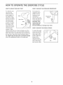
HOW TO ADJUST THE SEAT POST
For effective exer-
cise, the seat
shouHdbe at the
proper height, As
you pedal there
shouHdbe a slight
bend in your knees
when the pedaHs
are in the Howest
position, To adjust
the height of the
seat, first turn the
seat knob counter°
cHockwise and
remove it, Next,
Seat
HoHe
Knob
slide the seat post up or down and align one of the
adjustment holies in the seat post with the indicated
hoHein the Frame, Hnsertthe knob into the frame and
the seat post, and turn the knob cHockwise until it is
tight, Make sure that the knob is inserted through
one of the adjustment hotes in the seat post,
HOW TO ADJUST THE PEDALING RESISTANCE
To increase the
resistance of the
pedaHs,turn the
resistance knob
cHockwise; to
decrease the resis-
tance, turn the knob
countercHockwise,
Important: Stop
turning the knob
when turning it
becomes difficult, or damage may result,
HOW TO ADJUST THE PEDAL STRAPS
To adjust the pedaH
straps, first puHHthe
ends of the straps
off the tabs on the
pedaHs,Adjust the
straps to the
desired position,
and then press the
ends of the straps
back onto the tabs,
Tab
Strap
8

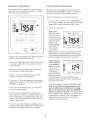
FEATURES OF THE CONSOLE
The consob features a sebction of modes that pro-
vide instant exercise feedback during your workouts,
The modes are described below,
PACE
2°'Fm
100_/
60 _/
40 _/
20 _
rpm
SCAN FAT CALS CALORIES
SPEED T_ME D_STANCE
/ , ......
L............. i', /
Speed--This mode displays your pedaling speed, in
miles per hour or kilometers per hour,
Time--This mode displays the elapsed time, Note:
if you stop pedaling for a few seconds, the time
mode will pause,
Distance--This mode displays the distance you
have pedaled, in miles or kilometers,
Calories--This mode displays the approximate
number of calories you have burned,
Fat Calories--This mode displays the approximate
number of fat calories you have burned (see FAT
BURNING on page 12),
Pulse--This mode displays your heart rate when
you use the pulse sensor,
Scan--This mode displays the speed, time, dis-
tance, calories, fat calories, and pulse modes, for a
few seconds each, in a repeating cycle, Note: The
pulse mode wiii be displayed only when the pulse
sensor is being used,
Pace--The pace bar shows your pedaling pace, in
revolutions per minute (RPM), Note: The pace mode
will always be displayed while you are pedaling,
HOW TO OPERATE THE CONSOLE
Make sure there are batteries in the console (see
BATTERY REPLACEMENT on page 11), if there is a
sheet of clear plastic on the console, remove it,
Follow the steps below to operate the console,
1, To turn on the console, press the ON/RESET but-
ton or begin pedaling, The entire display will briefly
appear; the console will then be ready for use,
2, Select one of the modes:
Scan mode--
When the power Mode indicators
is turned on, the SCAN CALORIES
scan mode will be
selected automati-
cally, One mode
indicator wiii
appear below the
word SCAN to SPEEDTIME DISTANCE
show that the
scan mode is
selected, and a second mode indicator will show
which mode is currently displayed, Note: if you
have selected a different mode, press the MODE
button repeatedly to reselect the scan mode,
Speed, time, dis-
tance, calories, SCAN FAT CALS CALORIES
or fat calories
mode--To select
one of these
modes for contin-
uous display, SPEED TIME DISTANCE
press the MODE
button repeatedly,
The mode indicators will show which mode is
selected, Make sure there is not a mode indicator
below the word SCAN,
To reset the display, press the ON/RESET button,
Note: The consoJe can display speed and dis-
tance in either miles or kiJometers. To change
the unit of measurement, press the ON/RESET
button for about five seconds. The letters mph or
km/h will appear in the display to show which unit of
measurement is selected, When the batteries are
replaced, it may be necessary to reselect the
desired unit of measurement,
9

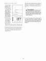
3, Measure your heart rate, if desired,
To measure your
heart rate, stop
pedaling and
pUaceyour thumb
on the puUsesen°
sor as shown, Do
not press too
hard, or the cir-
culation in your
thumb will be
restricted and
your pulse will
not be detected.
After a few sec-
onds, the heart-
shaped indicator
in the display will
flash steadily,
two dashes will
appear, and then
your heart rate
Pube Sensor
SCAN FAT CALS CALORIES
SPEED TIME DISTANCE
wHUbe shown, HoUdyour thumb on the pube sensor
for about 15 seconds for the most accurate reading,
if the dispUayed heart rate appears to be too high or
too bw, or if your heart rate is not dispUayed, Hft
your thumb off the puUsesensor for a few seconds,
Then, pUaceyour thumb on the pube sensor as
described above,
Make sure you are applying the proper amount of
pressure to the pulse sensor, Try the pulse sensor
several times until you become familiar with it,
Remember to sit still while measuring your heart
rate,
is not a medical device. Various factors
may affect the accuracy of heart rate read-
ings. The pulse sensor is intended onty as
an exercise aid in determining heart rate
trends in general
4, To turn off the console, simply wait for a few mino
utes, The console has an "auto-off" feature, if
the pedaJs are not moved and the consote but-
tons are not pressed for a few minutes, the
power will turn off automatically to save the
batteries.
10

MAINTENANCE AND TROUBLESHOOTmNG
Unspect and tighten aHparts of the exercise cycUereg-
uUady,RepUace any worn parts immediateUy,
To clean the exercise cycUe,use a damp cloth and a
small amount of mild detergent, Important: To avoid
damage to the console, keep liquids away from
the console and keep the console out of direct
sunlight.
BATTERY REPLACEMENT
Ufthe consoUe dispUaybecomes dim, the batteries
shouUd be repUaced; most consoUe proMems are the
resuUtof Uowbatteries, To repUacethe batteries, see
step 4 on page 5 and remove the consoUefrom the
handlebar, Next, see step 3 on page 5 and insert
three batteries into the consoUe, Reattach the consoUe
to the handUebar, being carefuU not to pinch the wires,
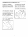
HOW TO ADJUST THE REED SWITCH
If the console does not display correct feedback, the
reed switch should be adjusted, In order to adjust the
reed switch, the left side shield must be removed,
Using an adjustable wrench, turn the Left Pedal (24)
clockwise and remove it, Next, remove the five M4 x
28mm Screws (41) from the Left Side Shield (17),
Carefully remove the Left Side Shield,
24
\
Next, turn the resistance knob to the lowest setting
With the left side shield removed, locate the Reed
Switch (43), Turn the Crank (21) until the Magnet (38)
is aligned with the Reed Switch, Loosen, but do not
remove, the M4 x 16mm Screw (49), Slide the Reed
Switch slightly closer to or away from the Magnet,
Retighten the Screw, Turn the Crank for a moment,
Repeat until the console displays correct feedback,
When the Reed Switch is correctly adjusted, reattach
the left side shield and the left pedal,
11

CONDiTiONiNG GUiDELiNES
The following guidelines wiii help you to plan your
exercise program. Remember that proper nutrition
and adequate rest are essential for successful resuUts.
WARN ING: Beforebegino n
this or any exercise program, consult your
physician. This is especialJy important for
persons over the age of 35 or persons with
pre-existing health problems.
The pulse sensor is not a medical device.
Various factors may affect the accuracy of
heart rate readings. The pulse sensor is
intended only as an exercise aid in determin-
ing heart rate trends in general
EXERCISE iNTENSiTY
Whether your goal is to burn fat or to strengthen your
cardiovascular system, the key to achieving the
desired results is to exercise with the proper
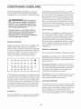
The proper intensity level can be found by using your
heart rate as a guide. The chart below shows recom-
mended heart rates for fat burning, maximum fat
burning, and cardiovascular (aerobic) exercise.
165 155 145 140 130 125 I15 _
145 138 130 125 128 110 103 _
125 120 115 110 105 95 90
20 30 40 50 60 70 80
To find the proper heart rate for you, first find your age
at the bottom of the chart (ages are rounded off to the
nearest ten years). Next, find the three numbers above
your age. The three numbers are your "training zone."
The lowest number is the recommended heart rate for
fat burning; the middle number is the recommended
heart rate for maximum fat burning; the highest num-
ber is the recommended heart rate for aerobic exer-
cise.
Fat Burning
To burn fat effectively, you must exercise at a relative=
ly low intensity level for a sustained period of time.
During the first few minutes of exercise, your body
uses easily accessible ca,@oiTy_?3.@calories for ener-
gy. Only after the first few minutes of exercise does
your body begin to use stored @tcalories for energy.
if your goal is to burn fat, adjust the intensity of your
exercise until your heart rate is near the lowest num-
ber in your training zone as you exercise. For maxi-
mum fat burning, adjust the intensity of your exercise
until your heart rate is near the middle number in your
training zone as you exercise.
Aerobic Exercise
if your goal is to strengthen your cardiovascular sys=
tem, your exercise must be "aerobic." Aerobic exer-
cise is activity that requires large amounts of oxygen
for prolonged periods of time. This increases the
demand on the heart to pump blood to the muscles,
and on the lungs to oxygenate the blood. For aerobic
exercise, adjust the intensity of your exercise until
your heart rate is near the highest number in your
training zone.
WORKOUT GUiDELiNES
Each workout should include the following three parts:
A warm-up, consisting of 5 to 10 minutes of stretching
and light exercise. A proper warm-up increases your
body temperature, heart rate, and circulation in prepa-
ration for exercise.
Training zone exercise, consisting of 20 to 30 min-
utes of exercising with your heart rate in your training
zone. Note: During the first few weeks of your exer-
cise program, do not keep your heart rate in your
training zone for longer than 20 minutes.
A coo!-down, with 5 to 10 minutes of stretching. This
will increase the flexibility of your muscles and will
help to prevent post-exercise problems.
EXERCISE FREQUENCY
To maintain or improve your condition, plan three work-
outs each week, with at bast one day of rest between
workouts. After a few months of regular exercise, you
may complete up to five workouts each week, if
desired. Remember, the key to success is make exer-
cise a regular and enjoyable part of your everyday life.
12

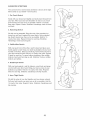
SUGGESTED STRETCHES
The correct form for severaU basic stretches is shown at the right,
Move sbwUy as you stretch--never bounce,
1. Toe Touch Stretch
Stand with your knees bent slightly and slowly bend forward from
your hips, Allow your back and shoulders to relax as you reach
down toward your toes as far as possible, Hold for 15 counts,
then relax, Repeat 3 times, Stretches: Hamstrings, back of knees
and back,
2. Hamstring Stretch
Sit with one leg extended, Bring the sob of the opposite foot
toward you and rest it against the inner thigh of your extended
leg, Reach toward your toes as far as possible, Hold for 15
counts, then relax, Repeat 3 times for each leg, Stretches:
Hamstrings, lower back and groin,
3. Caff/Achiltes Stretch
With one leg in front of the other, reach forward and place your
hands against a wall, Keep your back leg straight and your back
foot fiat on the floor, Bend your front leg, ban forward and move
your hips toward the wall, Hold for 15 counts, then relax, Repeat
3 times for each leg_ To cause further stretching of the achilles
tendons, bend your back leg as well, Stretches: Calves, achilles
tendons and ankles,
4. Quadriceps Stretch
With one hand against a wall for balance, reach back and grasp
one foot with your other hand, Bring your heel as close to your
buttocks as possible, Hold for 15 counts, then relax, Repeat 3
times for each leg, Stretches: Quadriceps and hip muscles,
5. runnerThigh Stretch
Sit with the sobs of your feet together and your knees outward,
Pull your feet toward your groin area as far as possible, Hold for
15 counts, then relax, Repeat 3 times, Stretches: Quadriceps and
hip muscles,
13

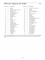
PART LiST--Model No. 831.215000 Ro2o B
Key No. Qty. Description Key No. Qty.
1 1 Frame 30
2 2 Stabilizer 31
3 2 M4 x 16mm Round Head Screw 32
4 4 33
5 1 Seat Post 34
6 1 M8 x 58mm Button BoUt 35
7 2 Handbbar Endcap 36
8 1 Seat Bushing 37
9 1 Seat Knob 38
10 7 M8 Nybn Locknut 39
11 1 C-Magnet 40
12 1 Seat 41
13 1 Upright 42
14 2 M4 x 5mm Screw 43
15 1 Handbbar 44
16 1 Consob 45
17 1 Left Side ShbUd 46
18 1 Right Side ShbUd 47
19 1 Resistance ControU/Cabb 48
20 1 Seat Post Bushing 49
21 1 50
22 1 Reed Switch CUamp 51
23 1 MIO Washer 52
24 1 Left PedaU 53
25 2 6200Z Bearing 54
26 1 Right PedaU 55
27 1 Resistance Knob 56
28 2 U-bracket #
29 1 Crank Nut #
4
2
4
4
3
1
1
1
1
1
1
5
8
1
Note: "#" indicates a nonqHustrated part, Specifications are subject to
call toll-free 1-866-699-3756. See the back cover of this manuaU for
parts,
Description
1
1
1
1
1
6
1
1
1
1
1
1
1
1
2
MIO x 65mm Carriage BoUt
EyeboUt
M6 Nut
MIO Nybn Locknut
M8 x 15mm Button Screw
BeUt
M4 x 19mm Screw
FUywheeU
Magnet
FUywheeUAxb
11mm Spacer
M4 x 28mm Round Head Screw
M8 Split Washer
Reed Switch/Wire
Crank Bearing Set
Lower Cable
M8 x 63mm Button Bolt
13mm Spacer
Spring
M4 x 16ram Screw
Cable Clamp Set
M6 x 40ram Bolt
M8 Flange Nut
Left Pedal Strap
Right Pedal Strap
Return Spring
Extension Wire
User's Manual
Allen Wrench
change without notice, If a part is missing,
information about ordering replacement
14

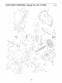
EXPLODED DRAWING--Model No. 831.215000 Ro2osB
\
\
3O
3
41
34
56
45
17
41L
42
49
, 43
49
12
6
20
14
14
44
29
/
/
32
18
35
53
38
54
/
i
26
i
i
i
39
25
32
I 46
11
52 4=
10
32
48
15

Your Home
For repaur - in your home - of aH major brand appliances, lawn and garden equipment,
or heating and cooling systems, no matter who made it, no matter who sold it!
For the replacement parts, accessories, and user's manuals thal you need to do-it-yourself.
For Sears professional installation of home appliances
and items like garage door openers and water heaters.
l o800o4-MYoHOME _ Anytime, day or ntght
_1=800=469=4663) tU°S.A, ana Canada_
wwwosearsocom wwwosears.ca
Our Home
For repair of carrvqn products like vacuums, lawn equipment,
and electronics, call or go on=line for the location of your nearest
Sears Parts and Repair Center.
1_800488-1222 Anytime, day or night (U.S.A. oniyj
www.seal's.oom
To purchase a protection agreement (U.S.A.)
or maintenance agreement (Canada) on a product serviced by Sears:
1-800o827o6655 (U.S.A._ 1-800o361-6665 (Canada)
Para pedir servicio de reparacion a domicilio y para ordenar piezas:
1-888-SU-NOGAR sM d =888=784=6427
FM SM
® Registered Trademark / Trademark / Service Mark of Sears, Roebuck and Co.
® Marca Registrada / TM Marca de FAbrica / SMMarca de Servicio de Sears, Roebuck and Co.
f
FULL 90 DAY WARRANTY
s
For 90 days from the date of purchase, if failure occurs due to defect in material or workmanship in this
Sears Bike Exerciser, contact the nearest Sears Service Center throughout the United States and
Sears will repair or replace the Bike Exerciser, free of charge,
This warranty does not apply when the Bike Exerciser is used commercially or for rental purposes,
This warranty gives you specific legal rights, and you may also have other rights which vary from state
to state,
Sears, Roebuck and Co., Dept. 817WA, Hoffman Estates, IL 60179
Part No, 222864 RO205B Printed in China © 2005 Sears, Roebuck and Co,
-
 1
1
-
 2
2
-
 3
3
-
 4
4
-
 5
5
-
 6
6
-
 7
7
-
 8
8
-
 9
9
-
 10
10
-
 11
11
-
 12
12
-
 13
13
-
 14
14
-
 15
15
-
 16
16


Weslo 831.215000 User manual
- Type
- User manual
- This manual is also suitable for
Ask a question and I''ll find the answer in the document
Finding information in a document is now easier with AI
Related papers
-
Weslo Pursuit 510 cs User manual
-
-
-
LIFESTYLER ALTA 831.2836 User manual
-
-
-
-
Weslo 831283101 User manual
-
-
Other documents
-
 DMI 802-2008-0099 Installation guide
-
NordicTrack SL 710 User manual
-
ProForm PFEXF495.0 User manual
-
-
Reebok EXERCISE CYCLE RBEX49840 User manual
-
-
-
Insportline Alfan User manual
-
-
NordicTrack CX 1055 User manual
