Page is loading ...

OPERATOR’S MANUAL
OBS-3A Turbidity and
Temperature Monitoring System
Revision: 2/16
Copyright © 2007- 2016
Campbell Scientific, Inc.


Limited Warranty
“Products manufactured by CSI are warranted by CSI to be free from defects
in materials and workmanship under normal use and service for twelve months
from the date of shipment unless otherwise specified in the corresponding
product manual. (Product manuals are available for review online at
www.campbellsci.com.) Products not manufactured by CSI, but that are resold
by CSI, are warranted only to the limits extended by the original manufacturer.
Batteries, fine-wire thermocouples, desiccant, and other consumables have no
warranty. CSI’s obligation under this warranty is limited to repairing or
replacing (at CSI’s option) defective Products, which shall be the sole and
exclusive remedy under this warranty. The Customer assumes all costs of
removing, reinstalling, and shipping defective Products to CSI. CSI will return
such Products by surface carrier prepaid within the continental United States of
America. To all other locations, CSI will return such Products best way CIP
(port of entry) per Incoterms ® 2010. This warranty shall not apply to any
Products which have been subjected to modification, misuse, neglect, improper
service, accidents of nature, or shipping damage. This warranty is in lieu of all
other warranties, expressed or implied. The warranty for installation services
performed by CSI such as programming to customer specifications, electrical
connections to Products manufactured by CSI, and Product specific training, is
part of CSI's product warranty. CSI EXPRESSLY DISCLAIMS AND
EXCLUDES ANY IMPLIED WARRANTIES OF MERCHANTABILITY
OR FITNESS FOR A PARTICULAR PURPOSE. CSI hereby disclaims,
to the fullest extent allowed by applicable law, any and all warranties and
conditions with respect to the Products, whether express, implied or
statutory, other than those expressly provided herein.”

Assistance
Products may not be returned without prior authorization. The following
contact information is for US and international customers residing in countries
served by Campbell Scientific, Inc. directly. Affiliate companies handle
repairs for customers within their territories. Please visit
www.campbellsci.com to determine which Campbell Scientific company serves
your country.
To obtain a Returned Materials Authorization (RMA), contact CAMPBELL
SCIENTIFIC, INC., phone (435) 227-9000. After an application engineer
determines the nature of the problem, an RMA number will be issued. Please
write this number clearly on the outside of the shipping container. Campbell
Scientific’s shipping address is:
CAMPBELL SCIENTIFIC, INC.
RMA#_____
815 West 1800 North
Logan, Utah 84321-1784
For all returns, the customer must fill out a “Statement of Product Cleanliness
and Decontamination” form and comply with the requirements specified in it.
The form is available from our website at www.campbellsci.com/repair. A
completed form must be either emailed to repair@campbellsci.com or faxed to
(435) 227-9106. Campbell Scientific is unable to process any returns until we
receive this form. If the form is not received within three days of product
receipt or is incomplete, the product will be returned to the customer at the
customer’s expense. Campbell Scientific reserves the right to refuse service on
products that were exposed to contaminants that may cause health or safety
concerns for our employees.

Safety
DANGER — MANY HAZARDS ARE ASSOCIATED WITH INSTALLING, USING, MAINTAINING, AND WORKING ON OR AROUND
TRIPODS, TOWERS, AND ANY ATTACHMENTS TO TRIPODS AND TOWERS SUCH AS SENSORS, CROSSARMS, ENCLOSURES,
ANTENNAS, ETC. FAILURE TO PROPERLY AND COMPLETELY ASSEMBLE, INSTALL, OPERATE, USE, AND MAINTAIN TRIPODS,
TOWERS, AND ATTACHMENTS, AND FAILURE TO HEED WARNINGS, INCREASES THE RISK OF DEATH, ACCIDENT, SERIOUS
INJURY, PROPERTY DAMAGE, AND PRODUCT FAILURE. TAKE ALL REASONABLE PRECAUTIONS TO AVOID THESE HAZARDS.
CHECK WITH YOUR ORGANIZATION'S SAFETY COORDINATOR (OR POLICY) FOR PROCEDURES AND REQUIRED PROTECTIVE
EQUIPMENT PRIOR TO PERFORMING ANY WORK.
Use tripods, towers, and attachments to tripods and towers only for purposes for which they are designed. Do not exceed design
limits. Be familiar and comply with all instructions provided in product manuals. Manuals are available at www.campbellsci.com or
by telephoning (435) 227-9000 (USA). You are responsible for conformance with governing codes and regulations, including safety
regulations, and the integrity and location of structures or land to which towers, tripods, and any attachments are attached. Installation
sites should be evaluated and approved by a qualified engineer. If questions or concerns arise regarding installation, use, or
maintenance of tripods, towers, attachments, or electrical connections, consult with a licensed and qualified engineer or electrician.
General
• Prior to performing site or installation work, obtain required approvals and permits. Comply
with all governing structure-height regulations, such as those of the FAA in the USA.
• Use only qualified personnel for installation, use, and maintenance of tripods and towers, and
any attachments to tripods and towers. The use of licensed and qualified contractors is highly
recommended.
• Read all applicable instructions carefully and understand procedures thoroughly before
beginning work.
• Wear a hardhat and eye protection, and take other appropriate safety precautions while
working on or around tripods and towers.
• Do not climb tripods or towers at any time, and prohibit climbing by other persons. Take
reasonable precautions to secure tripod and tower sites from trespassers.
• Use only manufacturer recommended parts, materials, and tools.
Utility and Electrical
• You can be killed or sustain serious bodily injury if the tripod, tower, or attachments you are
installing, constructing, using, or maintaining, or a tool, stake, or anchor, come in contact with
overhead or underground utility lines.
• Maintain a distance of at least one-and-one-half times structure height, 20 feet, or the distance
required by applicable law, whichever is greater, between overhead utility lines and the
structure (tripod, tower, attachments, or tools).
• Prior to performing site or installation work, inform all utility companies and have all
underground utilities marked.
• Comply with all electrical codes. Electrical equipment and related grounding devices should
be installed by a licensed and qualified electrician.
Elevated Work and Weather
• Exercise extreme caution when performing elevated work.
• Use appropriate equipment and safety practices.
• During installation and maintenance, keep tower and tripod sites clear of un-trained or non-
essential personnel. Take precautions to prevent elevated tools and objects from dropping.
• Do not perform any work in inclement weather, including wind, rain, snow, lightning, etc.
Maintenance
• Periodically (at least yearly) check for wear and damage, including corrosion, stress cracks,
frayed cables, loose cable clamps, cable tightness, etc. and take necessary corrective actions.
• Periodically (at least yearly) check electrical ground connections.
WHILE EVERY ATTEMPT IS MADE TO EMBODY THE HIGHEST DEGREE OF SAFETY IN ALL CAMPBELL SCIENTIFIC PRODUCTS,
THE CUSTOMER ASSUMES ALL RISK FROM ANY INJURY RESULTING FROM IMPROPER INSTALLATION, USE, OR
MAINTENANCE OF TRIPODS, TOWERS, OR ATTACHMENTS TO TRIPODS AND TOWERS SUCH AS SENSORS, CROSSARMS,
ENCLOSURES, ANTENNAS, ETC.


i
Table of Contents
PDF viewers: These page numbers refer to the printed version of this document. Use the
PDF reader bookmarks tab for links to specific sections.
1. Introduction ................................................................ 1
2. Precautions ................................................................ 1
3. Initial Inspection ......................................................... 1
3.1 Ships With ............................................................................................ 2
4. Overview ..................................................................... 2
4.1 OBS Sensor .......................................................................................... 2
4.2 Temperature and Optional Sensors ...................................................... 3
4.3 Optics and Turbidity Measurements .................................................... 3
5. Specifications ............................................................. 4
5.1 Measurement Range ............................................................................. 5
5.2 Accuracy .............................................................................................. 5
5.3 OBS Sensor .......................................................................................... 5
5.4 Other Data ............................................................................................ 5
5.5 Physcial ................................................................................................ 6
6. Operations .................................................................. 6
6.1 Instrument Setup .................................................................................. 6
6.1.1 Mounting Suggestions .................................................................. 6
6.1.2 Battery Installation ........................................................................ 8
6.2 Software Installation ............................................................................ 9
6.3 Running HydroSci.............................................................................. 10
6.4 Testing Sensors .................................................................................. 11
6.5 Water-Density and Barometric Corrections ....................................... 12
6.6 Menus ................................................................................................. 13
6.7 Connection ......................................................................................... 13
6.8 OBS-3A Configuration ...................................................................... 14
6.8.1 Information ................................................................................. 14
6.8.2 Operations ................................................................................... 15
6.8.3 Survey Configuration .................................................................. 20
6.8.4 Cyclic Configuration ................................................................... 22
6.8.5 Scheduled Configuration ............................................................ 25
6.8.6 Setpoint Configuration ................................................................ 29
6.9 Monitor .............................................................................................. 31
6.10 View Data .......................................................................................... 34
6.10.1 Data Retrieval ............................................................................. 34
6.10.2 Graphing and Printing ................................................................. 37
6.11 Show Terminal ................................................................................... 39
6.12 Shutdown ........................................................................................... 40
6.13 Excel Spreadsheets ............................................................................. 40
6.14 Erasing Memory Data ........................................................................ 41

Table of Contents
ii
7. Calibration ................................................................ 42
7.1 Turbidity ............................................................................................ 42
7.1.1 Equipment and Materials ........................................................... 42
7.1.2 Preparation ................................................................................. 43
7.1.3 HydroSci Software Steps ........................................................... 43
7.1.4 Making Turbidity Standards ....................................................... 44
7.2 Sediment ............................................................................................ 45
7.2.1 Equipment and Materials ........................................................... 46
7.2.2 Sediment Preparation ................................................................. 46
7.3 Salinity, Pressure and Temperature Calibrations .............................. 48
8. Troubleshooting ....................................................... 48
9. Maintenance ............................................................. 52
9.1 OBS Sensor ....................................................................................... 52
9.2 Pressure Sensor ................................................................................. 52
9.3 Conductivity Sensor .......................................................................... 53
9.4 Batteries ............................................................................................. 53
9.5 Pressure Housing ............................................................................... 54
9.6 Antifoulant Coatings ......................................................................... 54
9.7 User-serviceable Parts ....................................................................... 54
10. Factors Affecting OBS Response ........................... 54
10.1 Particle Size ....................................................................................... 55
10.2 Suspensions with Mud and Sand ....................................................... 56
10.3 High Sediment Concentrations .......................................................... 57
10.4 Sediment Color .................................................................................. 58
10.5 Water Color ....................................................................................... 58
10.6 Bubbles .............................................................................................. 59
10.7 Biological and Chemical Fouling ...................................................... 60
11. References ................................................................ 60
Figures
4-1. Anatomy of an OBS sensor ................................................................. 3
4-2. Optical particle detectors ..................................................................... 3
5-1. Dimensions .......................................................................................... 6
6-1. Components ......................................................................................... 8
6-2. Battery installation .............................................................................. 9
7-1. Effects of disaggregation ................................................................... 47
8-1. Component locations ......................................................................... 49
10-1. Response to sand, silt and clay .......................................................... 55
10-2. Effects of particle size ....................................................................... 56
10-3. Response at high sediment concentrations ........................................ 57
10-4. IR reflectance of minerals ................................................................. 58
10-5. Scattering intensity vs. angle ............................................................. 59
Tables
6-1. Working and Maximum Depths .......................................................... 7
7-1. Mixing Volumes for Formazin Standards ......................................... 45
7-2. Sample Durations for Sediment Calibrations .................................... 47
9-1. Battery Life (Hours) .......................................................................... 53

1
OBS-3A Turbidity and Temperature
Monitoring System
1. Introduction
The OBS-3A combines our OBS® probe with pressure, temperature, and
conductivity sensors in a battery-powered recording instrument. Batteries and
electronics are contained in a housing capable of operating at depths of up to
300 meters—depending on the pressure sensor installed.
Before installing the OBS-3A, please study:
• Section 2, Precautions
• Section 3, Initial Inspection
2. Precautions
• Although the OBS-3A is rugged, it should be handled as precision
scientific instruments.
• Maximum depth for the OBS-3A housing is 300 meters. Working depths
for individual instruments are limited by the installed pressure sensor. If
exceeded, the pressure sensor will rupture and the housing will flood.
• Bright sun near the surface (<2 meters) or black-colored sediments can
cause erroneous OBS readings.
• The OBS sensor must be kept clean to measure sediment concentration or
turbidity accurately.
• When cleaning the OBS-3A, do not use MEK, benzene, toluene, or
electronic cleaners as they could damage the OBS window.
• The conductivity sensor is very fragile and is enclosed in a hole behind the
OBS sensor. Do not poke it with any tool or object as the electrodes may
be damaged.
• Always put the OBS-3A in sleep mode when it will not be used for a while
to conserve battery capacity (see Section 6.12, Shutdown
(p. 40)).
3. Initial Inspection
• Upon receipt of the OBS-3A, inspect the packaging and contents for
damage. File damage claims with the shipping company.
• Check this information against the shipping documents to ensure the
correct product is received (see Section 3.1, Ships With
(p. 2)).

OBS-3A Turbidity and Temperature Monitoring System
2
3.1 Ships With
CSI pn 21229 Accessory Kit
ResourceDVD
CSI pn 29225 HydroSci Software on DVD
4. Overview
The heart of the OBS-3A is an OBS
sensor for measuring turbidity and
suspended solids concentrations by detecting near infrared (NIR) radiation
scattered from suspended particles. With a unique optical design, OBS sensors
perform better than most in situ turbidity sensors in the following ways:
1. Small size and sample volume,
2. Linear response and wide dynamic range,
3. Insensitivity to bubbles and organic matter,
4. Rejects effects of ambient light and temperature change.
The OBS-3A includes a temperature sensor and may be equipped with pressure
and conductivity sensors. Batteries and electronics are contained in a housing
capable of operating at depths of up to 300 meters, depending on which
pressure sensor is installed. A survey cable may be used to tow the OBS-3A
and a depressor weight by clamping a cable harness to the housing.
Depending on the number of sensors and the statistics selected, the OBS-3A
can log as many as 200,000 lines of data (one per hour for 23 years) including:
time, date, depth, nephelometric turbidity units (NTUs), °C, and salinity.
When sampling with a full suite of sensors, the unit will run about 300 hours.
When using the instrument for surveys, the data are captured by a PC running
the HydroSense software in the log file created at initialization.
4.1 OBS Sensor
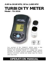
The OBS sensor consists of an infrared-emitting diode (IRED) with a peak
wavelength of 875 nm, four photodiodes, and a linear temperature transducer.
The IRED produces a conical beam with half-power points at 50°
(FIGURE
4-1). The IR scattered between 140° and 160° is detected after passing through
a daylight-rejection filter and is proportional to turbidity and sediment
concentration. See Section 5, Specifications
(p. 4).

OBS-3A Turbidity and Temperature Monitoring System
3
FIGURE 4-1. Anatomy of an OBS sensor
4.2 Temperature and Optional Sensors
Temperature is measured with a fast-response, stainless steel-clad thermistor.
Pressure is measured with a semiconductor piezoresistive strain gage.
Conductivity is measured with a four-electrode conduction-type cell. Working
depths for available pressure sensors are listed in TABLE 6-1.
4.3 Optics and Turbidity Measurements
Turbidity is the cloudy appearance of a liquid produced by light scattered from
suspended matter. It is an apparent optical property that depends on the size,
color, and shape of scattering particles, and the instrument used to measure it.
In accordance with standard method 2130B and ISO 7027, turbidity is usually
measured with a 90°-scatterance nephelometer and reported in NTUs.
Turbidity standards are discussed in Section 7, Calibration
(p. 42).
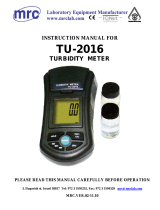
FIGURE 4-2. Optical particle detectors

OBS-3A Turbidity and Temperature Monitoring System
4
Light transmission in water is attenuated by scattering (deflection by water
molecules, and suspended matter) and absorption, which converts light to heat.
Attenuation, absorption, and scattering are inherent properties of water that are
affected only by impurities such as color and suspended organic matter.
Optically pure water is not readily available; however deionized water that has
passed through a 0.2 µm filter is adequate for most practical purposes.
There are dozens of turbidimeter designs, however most are configured in one
of the ways shown in FIGURE 4-2. These include: forward-scatterance, 90°
scatterance, and backscatterance nephelometers. Some instruments combine
two or more of these configurations and blend signals to produce a useful
output. The transmissometer measures attenuation, an inherent optical
property, but is not approved for turbidity measurements except by ISO 7027.
OBS sensors have superior linearity in turbid water but a transmissometer is
more sensitive at low concentrations (<~25 mg/L). Data from turbidimeters
made by different companies should be compared cautiously. Inconsistencies
between instruments results from variations in light sources, detectors, optical
configurations, and turbidity standards.
Can turbidity be converted to suspended solids concentrations and vise-
versa?
In most situations, conversions between turbidity and suspended solids
concentrations will give misleading results because the conversion equates to
an apparent optical property, in relative units, with one precisely defined in
terms of mass and volume; these are “apples and oranges”.
Conversion of turbidity to suspended solids concentration is recommended
only when:
• Measurements are made with the same turbidimeter.
• The turbidimeter is intercalibrated with a turbidity standard and suspended
matter from the waters to be monitored.
• Particle size and composition do not change over the monitoring period.
Compliance with the last condition is crucial but virtually impossible to verify
in the field because it is difficult to sample particles in their natural state and
preserve them for laboratory analysis in a consistent and meaningful way.
5. Specifications
Features:
• Measures turbidity with patented, field-proven OBS technology,
• Runs up to 8,000 hours on three D-cell batteries,
• Monitors sediment concentrations up to 5,000 mg/L and turbidity up
to 4,000 NTUs,
• Logs depth, wave height, wave period, temperature, and salinity.

OBS-3A Turbidity and Temperature Monitoring System
5
5.1 Measurement Range
Turbidity (AMCO Clear): 0.4 to 4,000 NTU
1
Mud (D
50
=20 µm):
0.4 to 5,000 mg/L
Sand (D
50
=250 µm):
2 to 100,000 mg/L
Pressure
2
: 0 to 10, 20, 50, 100, or 200 m
Temperature: 0 to 35 °C
Conductivity (salinity): 0 to 65 mS/cm (40 PSU, o/oo)
1
0 to 100, 0 to 250, 0 to 500, 0 to 1000, 0 to 2000, and 0 to 4000 NTU
ranges are available.
2
Range depends on pressure sensor option chosen.
5.2 Accuracy
Turbidity (AMCO Clear,
0 to 2,000 NTU): <2.0%
Mud (0.4 to 4,000 mg/L): 2.0% of reading
Sand (0.4 to 60,000 mg/L): 3.5% of reading
Pressure: ±0.5% full scale
Temperature: ±0.5 °C
Conductivity: 1%
5.3 OBS Sensor
Frequency: 5 Hz
Drift over time: <2% per year
Drift over temperature: 0.05% per °C
5.4 Other Data
Maximum size sample: 2048
Sampling rate when
connected to the PC: 1 to 25 Hz
Maximum data rate: 25 Hz (connected to PC), 5 Hz (used
autonomously)
Data capacity: 8 Mbytes

OBS-3A Turbidity and Temperature Monitoring System
6
Maximum number
of data lines: 200,000
Battery capacity: 18 A h
Maximum battery life: 8,000 hours
Data protocols: RS-232 / RS-485
Maximum housing depth: 300 m (984 ft)
Infrared wavelength: 850 nm
Operating temperature
range: 0 to 35 °C
Storage temperature range: –20 to 70 °C
5.5 Physcial
Length / diameter: 362 mm (14.3 in) / 76 mm (3.0 in)
Weight (w/o batteries): 1.5 kg (3.4 lb)
Weight (submerged): 0.2 kg (0.5 lb)
FIGURE 5-1. Dimensions
6. Operations
6.1 Instrument Setup
6.1.1 Mounting Suggestions
Maximum depth for the OBS-3A housing is 300 meters.
Working depths for individual instruments are limited by the
installed pressure sensor. If exceeded, the pressure sensor
will rupture and the housing will flood.
CAUTION
USE HOSE CLAMPS HERE
↑
76 mm
(3.0 in)
↓
362 mm (14.3 in)

OBS-3A Turbidity and Temperature Monitoring System
7
TABLE 6-1. Working and Maximum Depths
Pressure Sensor Working Depth Maximum Depth
0.2 Bar 0 to 2 meters 3 meters
1 Bar 0 to 10 meters 15 meters
5 Bar 0 to 50 meters 75 meters
10 Bar 0 to 100 meters 150 meters
20 Bar 0 to 200 meters 300 meters
(1 Bar = 10 dBar ≅ 10 meters of fresh water)
Schemes for mounting the OBS-3A will vary with applications; however, the
same basic precautions should be followed to ensure the unit is not lost or
damaged.
• The most important general precaution is to orient the unit so that the
OBS sensor “looks” into clear water without reflective surfaces.
• Nearly all exposed parts of the instrument are made of Delrin®, a strong
but soft plastic. Always pad the parts of the OBS-3A housing that will
contact metal or other hard objects with electrical tape or neoprene.
Expanded polyethylene tubes make excellent padding.
• Never mount the instrument by the end-caps or attach anything to them.
This could stress the screws holding the unit together, cracking either the
end-caps or pressure housing, and cause a leak.
Moorings
The most convenient means for mounting the unit to a frame or wire is to use
large high-strength nylon cable ties (7.6 mm or 0.3 in width) or stainless steel
hose clamps. Use at least six cable ties or two hose clamps for redundancy.
Position the clamps on the inner 2/3rds of the pressure tube, labeled “USE
HOSE CLAMPS HERE”, so stress is not transmitted to the ends (see FIGURE
5-1.). First cover the area(s) to be clamped with tape or 2 mm (1/16 in)
neoprene sheet. Clamp the unit to the mounting frame or wire using the
padded area. Do not tighten the hose clamps more than necessary to produce a
firm grip. Over tightening may crack the pressure housing and cause a leak.
Use spacer blocks when necessary to prevent chafing the unit with the frame or
wire.
Surveys
The OBS-3A will usually be towed from a cable harness for surveys. The
serial cable supplied with the unit is strong enough to tow the OBS-3A and a
5-kg depressor weight; however, the towing forces must be transmitted to the
pressure housing and not to the connector. To provide strain relief for the
connector, attach a cable grip about 30 cm above the SUBCONN® connector
(FIGURE 6-1) and attach a short length of 3 mm (1/8 in) wire rope to the cable
grip. Clamp the wire rope to the pressure housing in the clamping area with
two stainless steel hose clamps. Provide a small loop of slack cable between
the cable grip and connector and put chafe protection on the sensor head where
it contacts the wire rope.

OBS-3A Turbidity and Temperature Monitoring System
8
FIGURE 6-1. Components
6.1.2 Battery Installation
If unit is wet, perform the following operations with the unit held sensor end
up. Remove the three hex screws from the end with the handle and pull the cap
down and out of the housing.
Use caution if you have significantly changed elevation
since the OBS-3A may be under pressure and the cap could
pop out.
Wipe water from inside walls of the tube with a paper towel (FIGURE 6-2).
Slide the battery clip back and insert the batteries with the positive terminal (+)
toward the clip. Push the batteries down and slide the clip against the housing
wall to hold them in place. Inspect the O-ring in the cap and replace the cap
and screws.
CAUTION

OBS-3A Turbidity and Temperature Monitoring System
9
FIGURE 6-2. Battery installation
For extended deployment time, lithium batteries are a good alternative to
alkaline batteries. Campbell Scientific sells a D-cell-sized battery spacer
(pn 21906) that allows lithium D-cell batteries to be used with the OBS-3A.
Lithium D-cell batteries have a higher voltage than their alkaline counterparts,
necessitating the spacer. Campbell Scientific does not sell lithium D-cell
batteries.
6.2 Software Installation
Install HydroSci before connecting the OBS-3A to the computer.
Insert the ResourceDVD and type “OBS-3A” in the product window. Install
the HydroSci software. Follow the installation wizard to install the software.
This utility is your interface with the OBS-3A. As part of the installation, a
system-maintenance program is included. Communication drivers exist on the
CD.
The main purpose of this section is to explain how to program and operate the
OBS-3A with HydroSci. It covers: 1) turning the OBS-3A ON and testing the
sensors, 2) setting it up to sample in one of its four modes, 3) recording data
with a PC or uploading data from the OBS-3A, 4) importing data into a
spreadsheet, 5) plotting data, and 6) turning the OBS-3A OFF.
NOTE

OBS-3A Turbidity and Temperature Monitoring System
10
6.3 Running HydroSci
1. Select the HydroSci program to start the program.
2. Physically connect the OBS-3A to a PC with the test cable.
3. Select OBS-3A on the left side of the screen and select the
appropriate COM Port and Baud Rate at which to communicate. Press
the Connect button.
4. Upon successful connection, the Monitor screen will appear:

OBS-3A Turbidity and Temperature Monitoring System
11
5. Synchronize the OBS-3A clock with your PC by clicking Set OBS-3A
Time.
6. Configure your OBS-3A as desired. For more information on
configuration options, see Section 6.8, OBS-3A Configuration
(p. 14).
7. After you have finished interacting with your sensor, click on the
Connection tab and press the Disconnect button to disconnect from your
sensor.
6.4 Testing Sensors
Before daily operations and deployments, verify the instrument works by
pressing Survey Configuration and Start Survey. Then press Monitor to see
the plot.

OBS-3A Turbidity and Temperature Monitoring System
12
Blow on the temperature sensor to observe an increase in temperature (red
trace line on the top plot).
Dip the sensor in salty water and conductivity will increase (aqua trace line on
the top plot).
Wave your hand in from of the OBS sensor; the turbidity signal will fluctuate
and data will scroll (green trace line on the middle plot).
Blow into the pressure sensor and a small elevation in the pressure signal will
occur (blue trace line on bottom plot).
Click on OBS-3A Configurations | Information to view Sampling, Serial
Numbers, Calibration Dates, and Firmware.
6.5 Water-Density and Barometric Corrections
Since depths are estimated from pressure measurements, it is important to set
the water temperature and salinity so the OBS-3A can correct for water density
and calculate depth in meters or feet (this will not affect temperature or salinity
measurements). Also, the sensor measures absolute pressure so another
correction must be made for barometric pressure. Be sure to do this while the
OBS-3A is at the surface. Doing so when the instrument is submerged will
result in large errors in the depth measurement. The error will be
approximately equal to the instrument depth when the correction is made.
Depending on the magnitude of barometric pressure fluctuations at the
sampling site and the desired accuracy, you may want to correct data for
atmospheric effects using barometric pressure simultaneously recorded at a
nearby site.
/