Blue Sea Systems 8179 is a marine electrical AC main panel that serves 6 main purposes on any vessel: power distribution, circuit protection, circuit ON/OFF switching, reverse polarity indication, voltage and amperage metering, and condition indication. It is made of 0.125” 5052-H32 Aluminum Alloy with a textured Polyurethane finish and it has Double Pole AC / DC Magnetic Breakers that are rated for 65VDC/277V AC Maximum.
Blue Sea Systems 8179 is a marine electrical AC main panel that serves 6 main purposes on any vessel: power distribution, circuit protection, circuit ON/OFF switching, reverse polarity indication, voltage and amperage metering, and condition indication. It is made of 0.125” 5052-H32 Aluminum Alloy with a textured Polyurethane finish and it has Double Pole AC / DC Magnetic Breakers that are rated for 65VDC/277V AC Maximum.


-
 1
1
-
 2
2


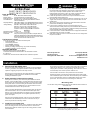
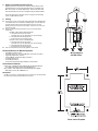
Blue Sea Systems 8179 Operating instructions
- Type
- Operating instructions
Blue Sea Systems 8179 is a marine electrical AC main panel that serves 6 main purposes on any vessel: power distribution, circuit protection, circuit ON/OFF switching, reverse polarity indication, voltage and amperage metering, and condition indication. It is made of 0.125” 5052-H32 Aluminum Alloy with a textured Polyurethane finish and it has Double Pole AC / DC Magnetic Breakers that are rated for 65VDC/277V AC Maximum.
Ask a question and I''ll find the answer in the document
Finding information in a document is now easier with AI
Related papers
-
Blue Sea Systems 8051 Operating instructions
-
-
-
-
-
-
-
Blue Sea Systems 8176 Operating instructions
-
-
Other documents
-
Hubbell Wiring Device-Kellems PD1123 Installation guide
-
Sea Ray 2013 SEA RAY 610 SUNDANCER Owner's manual
-
-
-
-
-
-
-
-