Page is loading ...

Alpha American Co., 10 Industrial Blvd., Palisade, MN 56469
www.yukon-eagle.com 1-800-358-0060
Oil/Wood/Coal - Gas/Wood/Coal
Warm Air Central Heating Furnaces
OWNER'S
MANUAL
• Assembly
• Installation
• Operation
• Repair Parts
• Maintenance Tips
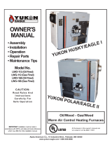
Model No.
LWO-112 (Oil Fired)
LWG-112 (Gas Fired)
LWO-168 (Oil Fired)
LWG-168 (Gas Fired)
CAUTION:
Read Rule s And
In st ru ct io ns
Ca re fu ll y F or Sa fe
Op er at io n
IMPORTANT: Installation must be made in
accordance with NFPA, and state and local ordinances
which may differ from this installation manual.
YUKON HUSKY/EAGLE I
YUKON POLAR/EAGLE II
All furnaces in this owner's manual are
UL Listed in UL File #MH11057

DANGER
RISK OF FIRE OR EXPLOSION
Do not burn garbage, gasoline, drain oil, kerosene, thinners, etc.
WARNING
RISK OF FIRE
Tightly close the firing door and ash door during operation.
Do not operate with flue draft exceeding .03" W.C.
Do not store flammable materials within marked installation clearance.
Frequently inspect and clean soot and/or creosote from the heat exchanger,
smoke pipe, and chimney.
Do not connect this unit to a chimney flue serving another appliance.
CAUTION
BLACK SURFACES ARE HOT
Keep children away. Do not touch.
Questions?
Visit www.yukon-eagle.com
or call
1-800-358-0060
For repair or replacement parts,
See back cover for details.
Before installing this
furnace, read and follow all
instructions in this manual.
It is recommended that a
heating professional installs
or supervises the entire
installation of the furnace,
ducts, chimney, electrical
and gas or oil hook ups.
FOR YOUR SAFETY:
If you smell gas:
1. Open windows
2. Do not touch electrical switches
3. Extinguish any open flame
4. Immediately call your gas supplier
FOR YOUR SAFETY:
Do not store or use gasoline or other
flammable vapors and liquids in the
vicinity of this or any other appliance.
2

TABLE OF CONTENTS
INTRODUCTION
Safety Statements & EPA Compliance . . . . . . . . . . . . . . . . . . . . . . . . . . . . . . . . . . . . . . . . . . . . . . .. . . . . . . . . . . . . .. . . . . .2, 4, 5-6
Specifications . . . . . . . . . . . . . . . . . . . . . . . . . . . . . . . . . . . . . . . . . . . . . . . . . . . . . . . . . . . . . . . . . . . . . . . . . . . . . . . . . . .7
Features and Benefits . . . . . . . . . . . . . . . . . . . . . . . . . . . . . . . . . . . . . . . . . . . . . . . . . . . . . . . . . . . . . . . . . . . . . . . . . . . . . . . . 8-11
Unpack and Check Cartons. . . . . . . . . . . . . . . . . . . . . . . . . . . . . . . . . . . . . . . . . . . . . . . . . . . . . . . . . . . . . . . . . . . . . . . . . . . . . . .12
PLAN YOUR INSTALLATION
Plan Your Installation . . . . . . . . . . . . . . . . . . . . . . . . . . . . . . . . . . . . . . . . . . . . . . . . . . . . . . . . . . . . . . . . . . . . . . . . . . . . . . . . . .13
Clearance to Combustible Material . . . . . . . . . . . . . . . . . . . . . . . . . . . . . . . . . . . . . . . . . . . . . . . . . . . . . . . . . . . . . . . . . . . . . . . . .14
Typical Installation . . . . . . . . . . . . . . . . . . . . . . . . . . . . . . . . . . . . . . . . . . . . . . . . . . . . . . . . . . . . . . . . . . . . . . . . . . . . . . . . . . . .15
Proper Chimney. . . . . . . . . . . . . . . . . . . . . . . . . . . . . . . . . . . . . . . . . . . . . . . . . . . . . . . . . . . . . . . . . . . . . . . . . . . . . . . . . . . . . . . 16
Combustion Air . . . . . . . . . . . . . . . . . . . . . . . . . . . . . . . . . . . . . . . . . . . . . . . . . . . . . . . . . . . . . . . . . . . . . . . . . . . . . . . . . . . . . . . .17
Furnace Located in Confined Space . . . . . . . . . . . . . . . . . . . . . . . . . . . . . . . . . . . . . . . . . . . . . . . . . . . . . . . . . . . . . . . . . . . . . . .18
INSTALLATION
Place Furnace . . . . . . . . . . . . . . . . . . . . . . . . . . . . . . . . . . . . . . . . . . . . . . . . . . . . . . . . . . . . . . . . . . . . . . . . . . . . . . . . . . . . . . . .19
Secondary Air Intake . . . . . . . . . . . . . . . . . . . . . . . . . . . . . . . . . . . . . . . . . . . . . . . . . . . . . . . . . . . . . . . . . . . . . . . . . . . . . . . . . . .19
Secondary Air Shut Off . . . . . . . . . . . . . . . . . . . . . . . . . . . . . . . . . . . . . . . . . . . . . . . . . . . . . . . . . . . . . . . . . . . . . . . . . . . . . . . . .19
Draft Tube . . . . . . . . . . . . . . . . . . . . . . . . . . . . . . . . . . . . . . . . . . . . . . . . . . . . . . . . . . . . . . . . . . . . . . . . . . . . . . . . . . . . . . . . .19
Oil Burner . . . . . . . . . . . . . . . . . . . . . . . . . . . . . . . . . . . . . . . . . . . . . . . . . . . . . . . . . . . . . . . . . . . . . . . . . . . . . . . . . . . . . . . . . . .20
Gas Burner . . . . . . . . . . . . . . . . . . . . . . . . . . . . . . . . . . . . . . . . . . . . . . . . . . . . . . . . . . . . . . . . . . . . . . . . . . . . . . . . . . . . . . . . . .20
Fuel Tanks and Fuel Lines . . . . . . . . . . . . . . . . . . . . . . . . . . . . . . . . . . . . . . . . . . . . . . . . . . . . . . . . . . . . . . . . . . . . . . . . . . . . . .21
Gas Piping . . . . . . . . . . . . . . . . . . . . . . . . . . . . . . . . . . . . . . . . . . . . . . . . . . . . . . . . . . . . . . . . . . . . . . . . . . . . . . . . . . . . . . . . . .22
Draw Collar . . . . . . . . . . . . . . . . . . . . . . . . . . . . . . . . . . . . . . . . . . . . . . . . . . . . . . . . . . . . . . . . . . . . . . . . . . . . . . . . . . . . . . . . . .23
Yukontrol DS-103 Damper Control . . . . . . . . . . . . . . . . . . . . . . . . . . . . . . . . . . . . . . . . . . . . . . . . . . . . . . . . . . . . . . . . . . . . . . . .23
Smoke Baffles . . . . . . . . . . . . . . . . . . . . . . . . . . . . . . . . . . . . . . . . . . . . . . . . . . . . . . . . . . . . . . . . . . . . . . . . . . . . . . . . . . . . . . . .24
Installing the Fan and Limit Control . . . . . . . . . . . . . . . . . . . . . . . . . . . . . . . . . . . . . . . . . . . . . . . . . . . . . . . . . . . . . . . . . . . . . . .25
Fume Sensor . . . . . . . . . . . . . . . . . . . . . . . . . . . . . . . . . . . . . . . . . . . . . . . . . . . . . . . . . . . . . . . . . . . . . . . . . . . . . . . . . . . . . . . .26
Electrical Wiring . . . . . . . . . . . . . . . . . . . . . . . . . . . . . . . . . . . . . . . . . . . . . . . . . . . . . . . . . . . . . . . . . . . . . . . . . .. . . . . . . . . .27
Mounting Thermostats and Settings . . . . . .. . . . . . . . . . . . . . . . . . . . . . . . . . . . . . . . . . . . . . . . . . . . . . . . . . . . . . . . . . . . . . . . . .28
24 Volt Field Wiring . . . . . . . . . . . . . . . . . . . . . . . . . . . . . . . . . . . . . . . . . . . . . . . . . . . . . . . . . . . . . . . . . . . . . . . . . . . . . .. . . . . . .29
Wiring Diagrams. . . . . . . . . . . . . . . . . . . . . . . . . . . . . . . . . . . . . . . . . . . . . . . . . . . . . . . . . . . . . . . . . . . . . . . . . . . . . . . . . . . . . .30-33
Connecting Smoke Pipe ... . . . . . . . . . . . . . . . . . . . . . . . . . . . . . . . . . . . . . . . . . . . . . . . . . . . . . . . . . . . . . . . . . . . . . . . . . . . . . .34
Barometric Draft Regulator. . . . . . . . . . . . . . . . . . . . . . . . . . . . . . . . . . . . . . . . . . . . . . . . . . . . . . . . . . . . . . . . . . . .. . . . . . . . . . .35-36
Testing for Efficiency . . . . . . . . . . . . . . . . . . . . . . . . . . . . . . . . . . . . . . . . . . . . . . . . . . . . . . . . . . . . . . . . . . . . . . . . . . . . .37
Test Procedure . . . . . . . . . . . . . . . . . . . . . . . . . . . . . . . . . . . . . . . . . . . . . . . . . . . . . . . . . . . . . . . . . . . . . . . . . . . . . . . . . . . . . . .38
Importance of Draft. . . . . . . . . . . . . . . . . . . . . . . . . . . . . . . . . . . . . . . . . . . . . . . . . . . . . . . . . . . . . . . . . . . . . . . . . . . . . . . . . . . . .39
OPERATION
Oil Firing Unit . . . . . . . . . . . . . . . . . . . . . . . . . . . . . . . . . . . . . . . . . . . . . . . . . . . . . . . . . . . . . . . . . . . . . . . . . . . . . . . . . . . . . . . .40
Starting Burner after Ignition Failure . . . . . . . . . . . . . . . . . . . . . . . . . . . . . . . . . . . . . . . . . . . . . . . . . . . . . . . . . . . . . . . . . . . . . . .40
Gas Firing Unit . . . . . . . . . . . . . . . . . . . . . . . . . . . . . . . . . . . . . . . . . . . . . . . . . . . . . . . . . . . . . . . . . . . . . . . . . . . . . . . . . . . . . . .41
Best Wood To Burn . . . . . . . . . . . . . . . . . . . . . . . . . . . . . . . . . . . . . . . . . . . . . . . . . . . .. . . . . . . . . . . . . . . . . . . . . . . . . . . . . . . .42
Best Burn Practices . . . . . . . . . . . . . . . . . . . . . . . . . . . . . . . . . . . . . . . . . . . . . . . . . . . .. . . . . . . . . . . . . . . . . . . . . . . . . . . . . . . .43
Proper Use of DS-103 Damper Control and After Burner Jet System . . . . . . .. . . . . . . .. . . . . . . . . . . . . . . . . . . . . . . . . . . . . . . .43
Firing Wood with Gas or Oil . . . . . . . . . . . . . . . . . . . . . . . . . . . . . . . . . . . . . . . . . . . . . . . . . . . . . . . . . . . . . . . . . . . . . . . . . . . . . .44
Coal Firing Unit. . . . . . . . . . . .. . . . . . . . . . . . . . . . . . . . . . . . . . . . . . . . . . . . . . . . . . . . . . . . . . . . . . . . . . . . . . . . . . . . . . . . . . . .45
Miscellaneous Coal Burning Tips . . . . . . . . . . . . . . . . . . . . . . . . . . . . . . . . . . . . . . . . . . . . . . . . . . . . . . . . . . . . . . . . . . . . . . . . .46
MAINTENANCE
Grate Care & Ash Removal . . . . . . . . . . . . . . . . . . . . . . . . . . . . . . . . . . . . . . . . . . . . . . . . . . . . . . . . . . . . . . . . . . . . . . . . . . . . .47
Smoke Pipe, Chimney & Secondary Heat Exchanger . . . . . . . . . . . . . . . . . . . . . . . . . . . . . . . . . . . . . . . . . . . . . . . . . . . . .48
Blower Adjustment . . . . . . . . . . . . . . . . . . . . . . . . . . . . . . . . . . . . . . . . . . . . . . . . . . . . . . . . . . . . . . . . . . . . . . . . . . . . . . . . . . . . .49
Duct Work and Blower Speed Adjustment. . . . . . . . . . . . . . . . . . . . . . . . . . . . . . . . . . . . . . . . . . . . . . . . . . . . . . . . . . . . . . . . . . . .50
Fire Brick Placement . . . . . . . . . . . . . . . . . . . . . . . . . . . . . . . . . . . . . . . . . . . . . . . . . . . . . . . . . . . . . . . . . . . . . . . . . . . . . . . .51
Oil Burner . . . . . . . . . . . . . . . . . . . . . . . . . . . . . . . . . . . . . . . . . . . . . . . . . . . . . . . . . . . . . . . . . . . . . . . . . . . . . . . . . . . . . . .52
Miscellaneous Maintenance . . . . . . . . . . . . . . . . . . . . . . . . . . . . . . . . . . . . . . . . . . . . . . . . . . . . . . . . . . . . . . . . . . . . . . . . . . . . .53-54
Over Heating Unit . . . . . . . . . . . . . . . . . . . . . . . . . . . . . . . . . . . . . . . . . . . . . . . . . . . . . . . . . . . . . . . . . . . . . . . . . . . . . . . . . . . . . .55
Exploded Views and Parts Lists. . . . . . . . . . . . . . . . . . . . . . . . . . . . . . . . . . . . . . . . . . . . . . . . . .. . . . . . . . . . . . . . . . . . . . . 56-65
Trouble Shooting . . . . . . . . . . . . . . . . . . . . . . . . . . . . . . . . . . . . . . . . . . . . . . . . . . . . . . . . . . . . . . . . . . . . . .66

Safety Statements
STOP FOR SAFETY!
Safe assembly, operating and maintenance practices should always be
followed whenever using any equipment. Wherever you see the caution sign,
extra safety precautions should be taken.
You must stop, read, and carefully follow the safety instructions before proceeding.
READ THROUGH THE ENTIRE MANUAL
It is recommended to read through the entire manual before beginning your
installation and/or operating your furnace. Follow all steps exactly.
UL LABEL AND NFPA PRACTICES
Areas of this manual refer to Underwriters Laboratories (UL)
and the National Fire Protection Association (NFPA).
UL & NFPA are non-profit organizations. This furnace must be installed according to NFPA codes.
UL is the oldest and largest public safety testing laboratory in the world. All furnaces in this manual are Listed by
the UL. They have passed all safety and efficiency requirements for both gas and oil in the U.S. The UL Listing
label is also your assurance that UL employees inspect our furnaces during the manufacturing process. This can
happen several times a year on an unannounced basis.
NFPA Codes, Standards, recommended practices, and guides referred to in this document are approved by the
American National Standards Institute. State and local codes are adopted from these standards.
4
DANGERS-CAUTION - FIRE HAZARDS
(BURN WOOD LOGS OR COAL ONLY)
Ducts and Plenums shall be constructed entirely of sheet metal
Do Not use flammable liquids to start a fire.
Do Not attempt to light a wood fire when gas or oil vapors are present.
Do Not install on a combustible floor.
In the event of an electrical power failure, be sure ash door and fire door remain closed.
Do Not install a power humidifier on warm air plenum.
Store all ashes in a metal container with a tight fitting lid. Allow ashes to cool before disposing of them.
Be sure there is a sufficient supply of outside combustion air to the area where the furnace is located.
Keep smoke pipe connection as short as possible with a minimum of 1-inch rise per linear foot from the
furnace to the chimney opening. Smoke pipe shall be 24 gauge galvanized or black pipe.
Before servicing, allow furnace to cool. Shut off electricity.
Familiarize yourself with this wood burning furnace before leaving it unattended.
Follow a regular service and maintenance schedule of furnace and chimney.
IN THE EVENT OF A CHIMNEY FIRE, CALL FIRE DEPARTMENT, AND THEN BE SURE ALL FURNACE
DOORS ARE CLOSED TIGHTLY. TURN OFF ELECTRIC POWER TO FURNACE.

5
This manual describes the installation and operation of the Models LWO-112,
LWG-112, LWO-168 and LWG-168 oil or gas and wood or coal burning
furnaces.
These furnace models meet the 2015 U.S. Environmental Protection Agency’s
(EPA) requirements for central forced air furnaces sold after May 15, 2015.
Under specific testing done by Underwriter’s Laboratories (UL) these furnace
models have been shown to deliver heat at the rates as follows:
● Models LWO-112 and LWG-112 have an output of 112,000 BTU’s
● Models LWO-168 and LWG-168 have an output of 151,000 BTU’s
WARNING: The wood furnaces in this manual have a manufacturer-set minimum
low burn rate that must not be altered. It is against federal regulation to alter this
setting or otherwise operate this furnace in a manner inconsistent with operating
instructions in this manual.
NOTE:
The 30-YEAR LIMITED WARRANTY: Alpha American Company will repair or replace, at its option, any casing or
heat exchanger which fails as a result of a defect in material or workmanship during the first year after purchase
or 18 months after date of manufacture, whichever comes first. Thereafter, replacement of any casing or heat
exchanger which fails as a result of a defect in material or workmanship at a cost to the purchaser of a proportion
of the existing suggested retail prices as follows:
HOW TO OBTAIN PERFORMANCE UNDER THIS WARRANTY
Purchaser should first contact the dealer or contractor from whom the Yukon Furnace was purchased, and notify
them of the defect or malfunction complained of, purchasers name, serial number and date of installation of the
Yukon Furnace. Parts to be replaced under this warranty should be delivered to the dealer or contractor, or
shipped directly to Alpha American Co., 10 Industrial Blvd., Palisade, MN 56469, freight prepaid. If satisfactory
performance of this warranty is not available through the dealer or contractor, the purchaser may contact Alpha
American Co., 10 Industrial Blvd., PO Box 20, Palisade, MN 56469 to obtain performance, but all such communi-
cations must be in writing.
CONDITIONS OF THE WARRANTY
Read the warranty sheet that is included with this furnace in its entirety! There are conditions that apply to the
performance of this warranty by Alpha American Company.
IMPORTANT! Operation of this furnace in a manner that is inconsistent with the
owner’s manual would void the warranty!
EPA Compliance Requirements
YEAR AFTER
PURCHASE
% OF RETAIL COST TO
PURCHASER
YEAR AFTER
PURCHASE
% OF RETAIL COST TO
PURCHASER
2-3 40% 7-10 60%
4-6 50% 11-30 80%

6
This furnace is designed to burn oil or gas and coal and natural wood only. Higher efficiencies and lower emis-
sions generally result when burning air dried seasoned hardwoods, as compared to softwoods or to green or
freshly cut hardwoods.
DO NOT BURN:
(1) Garbage;
(2) Lawn clippings or yard waste;
(3) Material containing rubber; including tires;
(4) Materials containing plastic;
(5) Waste petroleum products, paints or paint thinners, or asphalt products;
(6) Materials containing asbestos;
(7) Construction or demolition debris;
(8) Railroad ties or pressure-treated wood;
(9) Manure or animal remains;
(10) Salt water driftwood or other previously salt water saturated materials;
(11) Unseasoned wood; or
(12) Paper products, cardboard, plywood, or particle board. The prohibition against burning these
materials does not prohibit the use of fire starters made from paper, cardboard, saw dust, wax and
similar substances for the purpose of starting a fire in this furnace.
NOTE: This furnace can be started automatically using the oil or gas. Put wood in the firebox and turn up
the liquid fuel thermostat until the wood lights on fire. Once the fire is established, turn the wood
thermostat up to call for the temperature that you want.
WARNING: Burning these materials may result in release of toxic fumes or render
the furnace ineffective and cause smoke!
CAUTION: Do not turn wood thermostat down or off while the firebox is full. This
will cause the furnace to damper down and smolder, which could cause creosot-
ing of the furnace or chimney pipe.
EPA Compliance Requirements

MODEL LWO-112 (Oil)
Input Rating ......................................................................................................................................140,000 BTU/HR
Nozzle ..............................................................................................................................................1.0 G.P.H. - 80 H
Burner ........................................................................................................................................Wayne Model - MSR
MODEL LWG-112 (Gas)
Input Rating………...........................................................................................................................140,000 BTU/HR
Output Rating .....................................................................................................................................112,000 BTU/HR
NAT LP
Orifice.......................................................................................7/32" (.218 dia.) 9 (.136 dia.)
Manifold Pressure.....................................................................3.5 W.C.P 11.0 W.C.P.
Burner.............................................................................................................................Wayne Model P250-AF-DI-Y
MODEL LWO-112 or LWG-112
Blower Size (Belt Drive) ................................................................................................................................10" x 10"
Blower C.F.M ............................................................................................................................................. 800 - 1800
Motor Size........................................................................................................................................1/3 - 1/2 - 3/4 HP
Firebrick Lined..........................................................................................................(7) 9” x 6” x 2” • (8) 12” x 6” x 2”
Cast Iron Grates - Standard.......................................................................................................................(3) 16” x 8”
Wood Fire Door .............................................................................................................................................11" x 10"
Air Filter................................................................................................................................................. 20" x 25" x 1"
Firebox Size……………………................................................................................................................ 24" x 16"
MODEL LWO-168 (Oil)
Input Rating………...........................................................….…......................................................................189,000
BTU/HR Output Rating....................................................................................................................................151,000
BTU/HR Nozzle .....................................................….…….......… ...................................................1.35 G.P.H - 80 H
Burner.........................................................................….………................................................ Wayne Model - MSR
MODEL LWO-168 (Gas)
Input Rating........….…………............................................................................................................189,000 BTU/HR
Output Rating.....................................................................................................................................151,000 BTU/HR
NAT LP
Orifice ......................................................................................“F" (.257 dia.) “23” (.154 dia.)
Manifold Pressure.....................................................................3.5 W.C.P 11.0 W.C.P.
Burner.............................................................................................................................Wayne Model P250-AF-DI-Y
MODELS LWO-168, or LWG-168
Blower Size (Belt Drive).................................................................................................................................11" x 10"
Blower C.F.M ............................................................................................................................................1200 - 2000
Motor Size........................................................................................................................................1/3 - 1/2 - 3/4 HP
Firebrick ................................................................................(10) 9” x 6” x 2” • (7) 12” x 6” x 2” • (1) 9” x 4-1/2” x 2”
Cast Iron Grates - Standard.......................................................................................................................(3) 18” x 8”
Wood Fire Door................................................................................................................................ 13-1/4" x 13-1/4"
Air Filter..................................................................................................................................................20" x 25" x 1"
Firebox Size …………………………................................................................................................................24" x 18"
NOTE: It is recommended that a 2", non combustible, raised pad be used for the furnace.
This will prevent moisture from getting under the furnace and causing corrosion.
Questions? Visit www.yukon-eagle.com or call 1-800-358-0060
7
Specifications

YUKONTROL DS-103 SOLID-STATE
FURNACE CONTROL This is the solid-state
control that coordinates the gas or oil burner
function with the wood/coal damper so that your
home is always comfortable using your choice of
fuels.
MORE HEAT EXCHANGE SURFACE
MEANS LESS HEAT UP THE CHIMNEY
The secondary heat exchanger is made up of type
304 Stainless Steel tubes, which the heat produced
by the furnace, must pass through before entering
the chimney. This feature increases the heating
surface to 54 square feet. Standard gas or oil
furnaces have only 25-30 square feet.
GAS BURNER OPTION FOR AUXILIARY
FUEL Our gas model comes with a Wayne P250
AF DIN hi-efficiency gas burner. This burner
features a Honeywell electronic ignition and gas
valve. It is certified by Underwriters Laboratories to
provide up to 80.1% steady state efficiency. It can
be switched from LP Gas to Natural Gas or visa-
versa. This burner can be interchanged with our
Wayne model MSR oil burner at your option.
THE OIL (OR GAS) BURNER FIRES INTO
AN ENGINEERED PYROLITE HIGH
TEMPERATURE CERAMIC CHAMBER
WHICH ASSURES COMPLETE
COMBUSTION This flame is then directed
horizontally into the wood/coal firebox to
automatically ignite those fuels. This design assures
the gas or oil burner to be free of any wood/coal
smoke from the fire box.
THE EAGLE I INCORPORATES AN EASY
ACCESS CLEAN-OUT DOOR TO
MAINTAIN TOP HEATING EFFICIENCY
This is an openable door which connects the four
secondary heat tubes to the flue pipe that leads to
the chimney. Keeping the inside of your furnace
clean insures high efficiency.
2-INCH THICK HI-TEMPERATURE
FIREBRICK SURROUNDS THE
WOOD/COAL FIRE The EAGLE I furnace
features 180 pounds of firebrick. It is 18 inches
high on the side opposite the burner and the
backside of the firebox. It is 9 inches high on the
burner side. This firebrick not only protects the steel
from the extreme combustion temperatures in the
firebox, but it also retains a substantial amount of
heat after the wood/coal fire burns down.
AFTER-BURNER JET SYSTEM GIVES
MAXIMUM SOLID FUEL BURNING
EFFICIENCY Twenty percent of the air required
for proper wood/coal combustion is drawn in above
the firebox, and then distributed around the top of
the flame to create an afterburner effect. Forty
percent of the energy in wood/coal leaves the initial
flame in the form of an unburned gas (smoke). This
patented system burns these gases, thereby
substantially increasing the efficiency of the wood or
coal.
2 DIFFERENT STYLES OF HEAVY CAST
IRON GRATES It is imperative that 80 percent of
the air for combustion enters the firebox from below
a wood/coal grate to insure an efficient and clean
burning fire. Our standard heavy cast iron grate is
adequate for a wood fire. A much heavier cast iron
shaker grate is also available as an option for dense
coal use.
OIL BURNER OPTION FOR AUXILIARY
FUEL If oil is your preference for a back-up fuel,
your burner will be a Wayne model MSR 321-009
hi-efficiency oil burner. Features are a Stainless
Steel flame retention head and Honeywell Premium
controls. It is certified by Underwriters Laboratories
to provide up to 80.1 % steady state efficiency. If at
some time in the future, you decide you would
rather have LP or Natural Gas as your backup fuel,
this burner can be interchanged with our Wayne
P250 AF DIN gas burner. (A nice insurance policy.)
AIR CIRCULATING BLOWER AND
MOTOR The EAGLE I is designed with 10 inch
wide, ten inch- diameter belt drive blower. This
oversized blower turns slower than ordinary
furnaces because of its large size. It is therefore
quieter than most furnaces, Each EAGLE I is
equipped with a premium Class A motor with Class
B insulation, which means it will operate in a higher
temperature atmosphere. This motor also features
a 1.35 service factor, which means it has 35% more
power than a standard motor of the same size. Up
to four tons (48,000 BTU’s) of air conditioning can
be added to an EAGLE I.
8
Furnace Features - Eagle I- Husky

9
Furnace Features - Eagle I- Husky

Furnace Features - Eagle II - Polar
YUKONTROL DS-103 SOLID-STATE
FURNACE CONTROL This is the solid-state
control that coordinates the gas or oil burner
function with the wood/coal damper so that your
home is always comfortable using your choice of
fuels.
MORE HEAT EXCHANGE SURFACE
MEANS LESS HEAT UP THE CHIMNEY
The 8-inch diameter type 304 Stainless Steel
secondary heat exchanger recovers heat that would
normally go out the chimney. This added surface
plus the large firebox and massive primary heat
exchanger provide a total of 82 square feet of
heating surface compared to 30-35 square feet on a
comparable size oil or gas furnace.
GAS BURNER OPTION FOR AUXILIARY
FUEL Our gas model comes with a Wayne Model
P250 AF DIN hi-efficiency gas burner. This burner
features a Honeywell electronic ignition and gas
valve. It is certified by Underwriters Laboratories to
provide up to 80.1% steady state efficiency. It can
be switched from LP Gas to Natural Gas or visa-
versa. This burner can be interchanged with our
Wayne model MSR oil burner at your option.
2 DIFFERENT STYLES OF HEAVY CAST
IRON GRATES It is imperative that 80 percent
of the air for combustion enters the firebox from
below a wood/coal grate to insure an efficient and
clean burning fire. Our standard heavy cast iron
grate is adequate for a wood fire. A much heavier
cast iron shaker grate is also available as an option
for dense coal use.
A SEPARATE OIL OR GAS FIRE
CHAMBER ENGINEERED FOR THOSE
FUELS This is an important feature.
The chamber is lined with PYROLITE
TM
, an extremely
high temperature resistant ceramic material. It assures
efficient combustion of oil or gas, and directs those
flames into the wood burning chamber for automatic
ignition of the wood fire.
FIRE BRICK LINING EXTENDS
FURNACE LIFE Every Eagle furnace features
two inch thick fire brick, 18" high. Fire brick is used,
not only because of its lasting quality, but because it
also retains heat for better efficiency.
AFTER-BURNER
TM
JET SYSTEM GIVES
MAXIMUM SOLID FUEL BURNING
EFFICIENCY It extracts maximum BTUs from
the wood or coal. Superheated air is introduced
above the fire to ignite and extract heat from the
unburned combustible gases. Without this feature,
up to 40% of the available solid-fuel energy would
be wasted.
OIL BURNER OPTION FOR AUXILIARY
FUEL If oil is your preference for a back-up fuel,
your burner will be a Wayne model MSR 321-009
hi-efficiency oil burner. Features are a Stainless
Steel flame retention head and Honeywell Premium
controls. It is certified by Underwriters Laboratories
to provide up to 80.1 % steady state efficiency. If at
some time in the future, you decide you would
rather have LP or Natural Gas as your backup fuel,
this burner can be interchanged with our Wayne
P250 AF DIN gas burner. (A nice insurance policy.)
AIR CIRCULATING BLOWER AND
MOTOR The EAGLE II is designed with 10 inch
wide, ten inch- diameter belt drive blower. This
oversized blower turns slower than ordinary
furnaces because of its large size. It is therefore
quieter than most furnaces, Each EAGLE II is
equipped with a premium Class A motor with Class
B insulation, which means it will operate in a higher
temperature atmosphere. This motor also features
a 1.35 service factor, which means it has 35% more
power than a standard motor of the same size. Up
to 5 tons (60,000 BTU’s) of air conditioning can be
added to an EAGLE II.
10
Furnace Features - Eagle II- Polar

11
Furnace Features - Eagle II- Polar

Unpack and Check Your Cartons
INSPECT SHIPMENT
Your furnace is shipped complete in three cartons.
Note any damage to the shipping cartons. Remove all
items from your shipping cartons. Check all items
against the packing list below. Note any items lost or
damaged in shipment. Refer to the exploded view and
parts list in the back of the manual for the part names
and numbers of missing or damaged items. Keep the
small parts in the parts bag until you are ready to
install them.
PACKING LIST
1. Carton One: The basic furnace comes in the crate.
The blower cabinet below the filter door contains:
• Pre-assembled circulating fan, motor, belt and drives
• Drip shield for oil or gas burner
• The air filter lies on a frame inside the filter door,
below the flue outlet.
Inside the furnace wood-firing door are:
• Three wood grates (installed)
• Secondary air shut-off assembly
• Smoke pipe draw collar (Polar Unit Only)
• Primary air draft tube
• Door handle weldment and handle assembly for both
fire door and ash pan
Remove these items and set aside for later installation.
2. Carton Two: This accessory package contains the
following items:
• Secondary air intake cover
• Thermostats
• Barometric draft regulator
• Fan and limit control
• Yukontrol DS-103 damper assembly
• Transformer
• Wiring harness
• Fume sensor (gas only)
• Owner's manual
• Warranty sheet
• Moisture Meter (for measuring the moisture in fire wood)
• DVD “Getting to know your furnace”
Remove these items and set aside for later installation.
3. Carton Three: The oil or gas burner is in this
carton. It is pre-assembled and ready for installation.
A flue brush is in the warm air plenum opening. Remove this before installing plenums.
FIG. 1
12
Unpack and Check your Cartons
DS-103 DAMPER CONTROL
FAN AND LIMIT
CONTROL

Questions? Visit www.yukon-eagle.com or call 1-800-358-0060
PLAN YOUR INSTALLATION
It is recommended to read through the entire manual
before beginning your installation. Follow all steps exactly.
Reading this manual will also help you get all the benefits
from your furnace.
CAUTION: Read these rules and the
instructions carefully. Failure to follow these
rules and instructions could cause a
malfunction of the furnace. This could
result in death, serious bodily injury and/or
property damage.
IMPORTANT!
CHECKING THE FURNACE INSTALLATION AND
MAKING ADJUSTMENTS
It is imperative that a heating professional, before startup
and at the beginning of each heating season, inspects the
entire installation and make any necessary adjustments.
RULES FOR SAFE INSTALLATION AND OPERATION
1. Check your local codes. The installation must comply
with them.
2. Use only the type of fuel approved for this furnace.
Over firing will result in failure of heat exchanger and
cause dangerous operation.
3. Oil storage tanks, piping and valves should be installed
and tested in accordance with NFPA 31.
4. You must have a sufficient supply of combustion air to
the area in which the furnace is located. (See page 17).
5. Factory Built Chimneys: Connect this furnace to a
chimney that complies with NFPA 211. Factory built
chimneys for use with wood-burning appliances shall
comply with the HT requirements of UL 103 or
CAN/ULC-S629-M87. This means you must install what
is referred to as type HT all fuel chimney.
Masonry Chimneys: Connect this furnace to a
chimney that complies with NFPA 211. A field
constructed chimney of solid masonry units, bricks,
stones, listed masonry chimney units, or reinforced
Portland cement concrete that is lined with suitable
chimney flue liners and built in accordance with the
provisions of Chapter 4 of this standard.
6. Follow a regular service and maintenance schedule for
efficient and safe operation.
7. Before servicing, allow furnace to cool. Always shut off
electricity and fuel to furnace when working on it. This
will prevent electrical shocks or burns.
LOCATING THE FURNACE
The furnace should be located no more than 10 feet
away from chimney. You will need 1” rise per linear
foot of pipe as a minimum.
The furnace should be located with respect to building
construction and the placement of other equipment.
Consideration should be given to sufficient clearance.
Sufficient clearance provides adequate access for the
cleaning of surfaces; the replacement of air filters,
blowers, motors, controls and the chimney connector;
and for the lubrication and servicing of moving parts.
See Fig. 4 and 5.
UL Listed installation clearances from combustible
surfaces are 48" in the front of this furnace.
18" from the sides, rear and smoke pipe.
See Fig. 4.
A 2-INCH NON-COMBUSTIBLE PAD OR PAVERS
IS RECOMMENDED UNDER THE FURNACE.
FIG. 3
FIG. 2
Unit Dimensions
LWO-112 & LWG-112
LWO-168 & LWG-168
13
Plan Your Installation

FIG. 4
ABOVE TOP OF
WARM AIR PLENUM
FROM THE
FRONT
FROM SIDES
AND BACK
FROM CHIMNEY
CONNECTOR
6 FT OF
PLENUM
BEYOND
6 FT OF
PLENUM
CLEARANCES TO COMBUSTIBLES
6” 48” 18” * 18” 6” 1”
! !
CAUTION
ALL METAL DUCTING SHALL BE
USED AND INSTALLED WITH
CLEARANCES SHOWN HERE
Floor Joist or Combustible Material
FURNACE
WARM AIR
PLENUM
6 Inches
6 Feet
Heat Supply
Ducts
1”
1” CLEARANCE TO
COMBUSTIBLES
BEYOND 6’ TO A
POINT WHERE
THERE IS A
CHANGE IN
DIRECTION OF
90 DEGREES OR
MORE.
Top View
Top View
Warm Air
Plenum
Cold Air
Plenum
18” MIN
18” MIN
8” Dia.
Flue Pipe
Combustible
Walls
NOTE:
DUCT AND PLENUMS SHALL BE
CONSTRUCTED ENTIRELY OF
SHEET METAL.
* Up to 50% less clearance between combustible
walls and chimney connector to furnace and
ducts is allowed if insulated according to NFPA
Standard 90B or your local building code. This
copyrighted book is available from the National
Fire Protection Association, Inc., PO Box 9101,
Quincy, MA 02269-9101
SERVICE CLEARANCE OF 24 INCHES
MINIMUM REQUIRED TO SERVICE
BLOWER
FLOOR TO BE NON-COMBUSTIBLE MATERIAL
14
Plan Your Installation

FIG. 5
IMPORTANT!
AIR CONDITIONING COIL MUST
BE INSTALLED WITH A METAL
CONDENSATE PAN.
DO NOT USE PLASTIC PAN
DUCTS SHOULD BE LARGE ENOUGH
TO HANDLE GRAVITY AIR FLOW IN THE
EVENT OF ELECTRIC POWER OR FURNACE
FAN FAILURE.
IMPORTANT!
DUCTS AND PLENUMS SHALL BE
CONSTRUCTED ENTIRELY OF
SHEET METAL.
TYPICAL INSTALLATION
15
Plan Your Installation

PROPER CHIMNEYS
The National Fire Protection Association (NFPA) requires that all factory built chimneys be Listed and
installed in accordance with conditions of the Listing in the manufacturers instructions. NFPA also
requires that your chimney extend at least three (3) feet above the highest point when it passes through
the roof and at least two (2) feet higher than any portion of the building within ten (10) feet of the
chimney.
Factory built chimneys must be what NFPA refers to in NFPA 211 1-5.217.4 as Type HT. HT is an
abbreviation meaning high temperature.
Masonry Chimneys as referred to in NFPA 211 1-5.2.17.6, a field constructed chimney of solid masonry
units, bricks, stones, listed masonry chimney units, or reinforced concrete that is lined with suitable chim-
ney flue liners and built with the provisions of Chapter 4 of this standard.
As described in NFPA 54 (National Fuel Gas Code) section 7.5.5 (c) A Listed combination gas and solid
fuel appliance equipped with a manual reset device to shut off gas to the main burner in the event of flue
gas spillage shall be permitted to be connected to a single chimney flue. The chimney flue shall be sized
to properly vent the appliance.
All gas-solid fuel and oil-solid fuel combination furnaces in this manual are Underwriters Laboratories
Listed for one flue.
RIDGE
More than 10 ft.
(3.1m)
10 ft. (3.1m)
2 ft. (0.61m)
minimum
Chimney 3ft. (0.92m)
minimum
RIDGE
Less than 10 feet
(3.1m)
2 ft. (0.61m)
minimum
Chimney 3 ft. (0.92m)
minimum
CHIMNEY TERMINATION (LESS THAN 10 FEET)
CHIMNEY TERMINATION (MORE THAN 10 FEET)
16
WARNING: CHECK YOUR CHIMNEY.
The chimney should be no less than
8 inches inside diameter or equal. The
chimney is a very important part of your
heating system. It must be the right size, properly
constructed and in good condition. No furnace can
function properly with a bad chimney. The chimney
must supply a draft of at least -.03 Water Column.
If possible, use a 15 foot or higher chimney. Add
an additional foot to chimney for each 1000 feet of
elevation above sea level.
Plan Your Installation

COMBUSTION AIR
Make-up outside air must be provided to furnace for
proper fuel combustion. This is provided by openings
to outside of building. These openings shall have
unobstructed areas not less than the areas of the flue
pipe. See Figs. 6, 7 and 8
IMPORTANT:
Outside air is needed to replace air used by
the burner and wood/coal combustion
process. Outside air is required to replace
air used for taking the by-products of
combustion out the chimney. Outside air is
needed to replace air expelled by kitchen or
bathroom fans. It is also needed to replace
air expelled by water heater chimneys, fans
or dryers. See Figs. 6, 7 and 8
Failure to provide outside air to the furnace area will
result in negative pressure, or vacuum, in the home.
Smoke from the wood fire may not be drawn up the
chimney. This causes creosote buildup and sometimes
causes smoke to enter furnace room.
See Figs. 6, 7, and 8
WARNING: You must provide for
enough fresh air to assure proper
combustion. The fire in the furnace uses
oxygen and must have a continuous
supply. The air in a house contains only enough
oxygen to supply the furnace for a short time.
Outside air must enter the house to replace that
used by the furnace.
FIG. 7
FIG. 6
FIG. 8
Gooseneck Trap
17
Plan Your Installation

Questions? Visit www.yukon-eagle.com or call 1-800-358-0060
FURNACE LOCATED IN CONFINED SPACE
When the furnace is in a utility room, install two open
grilles. (See Fig. 9) Place them in a wall or door opening
to the rest of the house. One grille will supply combustion
air.
Locate it near the floor. The other grille is for ventilation.
Locate it close to the ceiling. Each grille must have a free
area. It should be not less than one square inch for each
1000 BTU/hr. of the total input rating of appliances in
confined space.
FOR EXAMPLE: Your furnace is rated at 150,000 BTU
per hour. The water heater is rated 30,000 BTU per hour.
The total is 180,000 BTU per hour. You need two grilles,
each with 180 square inches of free opening. Metal grilles
have about 60% free (open) area. Therefore, you need
two metal grilles with 300 square inches each of louvered
area. The height should be about half the width.
FIG. 9
SIZE
1/4” MESH
SCREEN
BTU
WOOD
LOUVERS
BTU
METAL
LOUVERS
BTU
3-1/4 X 12 INCH
8 INCH ROUND
8 X 12 INCH
8 X 16 INCH
144,000
200,000
382,000
512,000
36,000
50,000
96,000
128,000
108,000
150,000
288,000
384,000
BTU Per Hour Input*
* Based on opening covered by 1/4 inch mesh screen, wood or metal louvers.
FRESH AIR DUCT CAPACITIES
Fresh air duct capacities for duct supplying fresh air
18
Plan Your Installation

FIG. 11
PLACE FURNACE
Review all instructions in the Planning Your
Installation section. Place the furnace in the pre-
selected location.
Refer to Figs. 4 & 5 (on pages 14 and 15 ) in the
Planning Your Installation section. Make sure the
furnace is level.
SECONDARY AIR INTAKE COVER
1. Remove secondary air intake cover from
accessory package and align over mounting
holes located above fire door assembly on face
of furnace. See Fig. 11.
2. Insert 12 ea. # 10 x 3/4 hex HD drill screws
(furnished with cover) through mounting holes
and tighten.
SECONDARY AIR SHUT OFF
MODELS LWO-112 & LWG-112 ONLY
1. Remove round secondary air shut off disc from
plastic bag.
2. Screw the shutoff disc to the intake cover just
installed.
Opening the disc when burning wood/coal,
provides room air to the round perforated tubes
between the top and bottom row of firebrick,
thereby causing secondary combustion of the
unburned wood/coal gases as they leave the initial
flame. This patented feature increases wood/coal
burning efficiency up to 40% while reducing
smoke and creosote. When burning gas or oil for
extended periods of time, this disc should be
closed.
It is not necessary to provide this shutoff disc on
models LWG-168 and LWO-168. Maximum
efficiency is achieved without this disc.
FIG. 10
SMOKE
PIPE
RETURN AIR
PLENUM
WARM AIR
PLENUM
DS-103 DAMPER
CONTROL
24-VOLT
TRANSFORMER
19
FUME SENSOR
(GAS MODEL ONLY)
Installation
YUKONTROL DS-103 DAMPER CONTROL
NOTE: Refer to the wiring diagrams section in this
manual.
Remove control from accessory box and install as
follows:
1. Remove the four screws that hold the gasket to the
DS-103 damper control.
2. Mount the DS-103 damper control to the draft tube
using screws removed above. Make sure gasket
stays in place. See Fig. 11
3. Loosen the two screws located at slotted end of
draft tube, and remove remaining 10 screws. Make
sure gasket stays in place.
4. Mount DS-103 damper control and draft tube
assembly to furnace as shown. See Fig. 11
5. The electrical connections will be completed later in
the Installation Instructions.
FIG. 12
SECONDARY AIR INTAKE COVER
DS-103
DAMPER
CONTROL

FIG. 13
OIL BURNER INSTALLATION
• Model LWO-112 burner has a (140,000 BTU input)
1.00 G.P.H. 80 degree H nozzle installed at the factory. •
Model LWO-168 burner has a (189,000 BTU input)
1.35 G.P.H. 80 degree H nozzle installed at the factory.
Install burner as follows:
1. Make sure hole in side of pyrolite chamber lines up
with hole in the end of the blast tube. (See Fig. 13)
2. Remove nuts from burner mounting studs on face of
the furnace.
3. Install drip shield (shipped in blower compartment)
over studs. Place gasket (packed in burner box) over
drip shield. (Fig. 14)
4. Assemble mounting flange over burner blast tube (flat
surface away from burner housing). Do not tighten
clamping screws.
5. Insert burner tube into furnace. Align holes in
mounting flange over studs on furnace. Replace nuts
removed in step 2 above and tighten.
6. Insert burner so that burner housing is tight against
mounting flange (end of blast tube should be flush
with inside of pyrolite chamber). Level burner and
tighten clamping screws.
GAS BURNER INSTALLATION
• Model LWG-112 A 7/32" dia. orifice has been installed
at the factory. (140,000 BTU input - nat. gas). To
convert to LP gas, see manufacturers instructions
packed with the burner.
• Model LWG-168 A "F" (.257 dia.) orifice has been
installed at the factory (189,000 BTU input - nat. gas).
To convert to LP gas, see manufacturers instructions
packed with burner.
Install burner as follows:
1. Make sure hole in side of pyrolite chamber lines up
with hole in the end of the blast tube. (See Fig. 13)
2. Remove nuts from burner mounting studs on face of
the furnace.
3. Install drip shield (shipped in blower compartment)
over studs. Place gasket (packed in burner box) over
drip shield. (Fig. 14)
4. Assemble mounting flange over burner blast tube (flat
surface away from burner housing). Do not tighten
clamping screws.
5. Insert burner tube into furnace. Align holes in
mounting flange over studs on furnace. Replace nuts
removed in step 2 above and tighten.
6. Insert burner so that burner housing is tight against
mounting flange (end of blast tube should be flush
with inside of pyrolite chamber). Level burner and
tighten clamping screws.
FIG. 14
Drip
Shield
CUT AWAY VIEW
BURNER COMBUSTION CHAMBER
Burner
Blast Tube
Pyrolite Liner
In combustion
Chamber
20
IMPORTANT!
PYROLITE LINER (FIG 13) MUST BE
CHECKED REGULARLY TO ENSURE
INTEGRITY OF MATERIAL IS GOOD.
FAILURE TO REPLACE PART WHEN
NECESSARY MAY RESULT IN DAMAGE
TO THE STEEL CHAMBER.
Installation
/