Page is loading ...

IN-E-HL-NT-V2_17
Rotronic AG
Bassersdorf, Switzerland
Document code
Unit
HygroLog HL-NT data logger:
instruction manual
Instruction Manual
Document Type
Page
1 of 75
Document title
© 2017; Rotronic AG IN-E-HL-NT-V2_17
HygroLog HL-NT Data Logger
Instruction Manual

IN-E-HL-NT-V2_17
Rotronic AG
Bassersdorf, Switzerland
Document code
Unit
HygroLog HL-NT data logger:
instruction manual
Instruction Manual
Document Type
Page
2 of 75
Document title
© 2017; Rotronic AG IN-E-HL-NT-V2_17
Table of contents:
1. Overview.................................................................................................................................. 4
1.1 General ................................................................................................................................ 4
1.2 Compatibility with previous models of probes and docking stations ................................... 6
2. General description of the HygroLog HL-NT ....................................................................... 7
2.1 Models ................................................................................................................................. 7
2.2 Required accessories .......................................................................................................... 8
2.3 HygroLog HL-NT inputs ....................................................................................................... 9
2.4 Power supply ..................................................................................................................... 12
2.5 Memory card ...................................................................................................................... 14
2.6 LED Indicators ................................................................................................................... 15
2.7 Beeper ............................................................................................................................... 15
2.8 HygroLog HL-NT functions ................................................................................................ 16
2.9 HygroClip 2 probe functions .............................................................................................. 21
2.10 Event tracking .................................................................................................................... 21
2.11 Operating limits (electronics only) ..................................................................................... 25
3. Docking stations for the HygroLog HL-NT ........................................................................ 26
3.1 Models ............................................................................................................................... 27
3.2 Installation .......................................................................................................................... 32
3.3 Relay contacts ................................................................................................................... 39
4. Pin-out diagrams .................................................................................................................. 40
5. HW4 software ........................................................................................................................ 43
5.1 Computer/Operating System Requirements ..................................................................... 43
5.2 Operating System Compatibility ........................................................................................ 44
5.3 Settings and functions accessible only with HW4 ............................................................. 45
6. ERES regulatory compliance .............................................................................................. 47
7. Getting started ...................................................................................................................... 48
8. Stand-alone operation ......................................................................................................... 48
8.1 Operating modes ............................................................................................................... 48
8.2 Display and keypad ........................................................................................................... 49
8.3 Display modes ................................................................................................................... 51
8.4 Settings and functions accessible from the Keypad .......................................................... 52
8.5 Internal function menu (models with display and keypad)................................................. 53
9. Operation on a network ....................................................................................................... 59
9.1 Baud rate and communications protocol compatibility requirements ................................ 59
9.2 Ethernet local area network ............................................................................................... 60
9.3 RS-485 multi-drop network ................................................................................................ 61
9.4 General wiring guidelines .................................................................................................. 63
9.5 Guidelines for RS-485 wiring ............................................................................................. 64
10. HygroClip probe adjustment procedures ..................................................................... 65
10.1 Single Point adjustment ..................................................................................................... 65
10.2 Multi-Point adjustment ....................................................................................................... 67
11. Warnings and useful tips ................................................................................................ 67
12. Communications protocol .............................................................................................. 68
13. Firmware updates ............................................................................................................ 68
14. Specifications .................................................................................................................. 69
15. Accessories ...................................................................................................................... 73
16. Supporting documents ................................................................................................... 74
17. Document releases .......................................................................................................... 75

IN-E-HL-NT-V2_17
Rotronic AG
Bassersdorf, Switzerland
Document code
Unit
HygroLog HL-NT data logger:
instruction manual
Instruction Manual
Document Type
Page
3 of 75
Document title
© 2017; Rotronic AG IN-E-HL-NT-V2_17
Applicability:
This manual is valid for instruments with firmware version 2.0x (see MENU - Instrument or check
using the ROTRONIC HW4 software, Device Manager). Examples: 2.0a, 2.0b. Changes in the last
character of the version number reflect minor changes in the internal software of the instrument
that do not affect the manner in which the instrument should be operated.

IN-E-HL-NT-V2_17
Rotronic AG
Bassersdorf, Switzerland
Document code
Unit
HygroLog HL-NT data logger:
instruction manual
Instruction Manual
Document Type
Page
4 of 75
Document title
© 2017; Rotronic AG IN-E-HL-NT-V2_17
1. Overview
1.1 General
HygroLog HL-NT is a series of networkable data loggers primarily designed for use with the
HygroClip 2 digital humidity-temperature probes.
Depending on the model and options, the HygroLog HL-NT main features are as follows:
o Internal probe input: allows installing a HC2-S humidity-temperature probe internally to
prevent unauthorized removal. This input can also be connected to an external probe by
means of an extension cable.
o Inputs for up to 6 additional external probes, including analog probes and 4-wire passive
RTD probes.
o Monitoring of up to two external contacts (relay output, door, etc.).
o Large recording capacity with removable flash memory card. Up to 750,000 values can be
recorded with the standard 64 MB card. Cards with a capacity of up to 1 GB are available.
o Display with backlight and keypad. This allows the HygroLog HL-NT to operate as a stand-
alone unit after initial configuration with the HW4 software.
o Compliance with FDA 21 CFR Part II and GAMP regulations regarding electronic records
and electronic signatures (ERES).
o Compatible with Ethernet networks (TCP / IP protocol – LAN or WLAN).
o Dedicated RS-485 network of up to 64 HygroLog HL-NT per communication port
o Simultaneous data recording and data display either locally or on a PC.
Internal power for both the HygroLog HL-NT and probes is provided by a 9V battery (factory
standard) or by a 9V rechargeable battery (user supplied).
The HygroLog HL-NT requires a docking station to (a) to power the HygroLog HL-NT with an
external AC adapter, (b) to configure the HygroLog HL-NT and communicate with a PC, (c) to
connect the HygroLog HL-NT to a network and (d) to mount the HygroLog HL-NT to a wall or to
place the HygroLog HL-NT on the optional desk-top stand.

IN-E-HL-NT-V2_17
Rotronic AG
Bassersdorf, Switzerland
Document code
Unit
HygroLog HL-NT data logger:
instruction manual
Instruction Manual
Document Type
Page
5 of 75
Document title
© 2017; Rotronic AG IN-E-HL-NT-V2_17
The most basic model of docking station simply provides a means of mounting the HygroLog HL-
NT to a wall and of powering the HygroLog HL-NT with an external AC adapter. All other models
offer the same functionality as the basic model and also provide a communication port (RS232,
USB or RJ45 / Ethernet) as well as additional inputs for probes and external contacts. Docking
stations with an RS232 or USB port are used to connect the HygroLog HL-NT directly to a PC.
Docking stations with an RJ45 connector are used to connect the HygroLog HL-NT to an Ethernet
LAN. In both cases, the docking station features an RS485 port that can be used to connect up to
64 HygroLog HL-NT in a multi-dropped arrangement (dedicated RS-485 network). This is useful
when the PC does not have an Ethernet network interface card or when the number of available
Ethernet ports is limited. Direct connection to an Ethernet LAN allows, in principle, an unlimited
number of HygroLog HL-NT to be put on a network monitored by the HW4 software. HW4 allows
any combination of RS-232, USB, Ethernet and RS-485 connections.
When equipped with a docking station, the HygroLog HL-NT can be used together with the
ROTRONIC HW4 software for Windows based PCs (version 2.3.0 or higher). In addition to
providing for the networking of large quantities of data loggers and other instruments, the main
functions of HW4 include:
o Configuration of the HygroLog HL-NT and docking station
o Programming of the HygroLog HL-NT logging function
o Manual or automatic downloading of the data recorded by the HygroLog HL-NT
o On-line data monitoring and direct data recording by the PC
o Automatic generation of graphs and data tables
o Monitoring of the networked instruments and data for alarm conditions
o Alarm reporting
o Maintenance of audit trails
o Calibration and adjustment of the HygroClip 2 probes
o Generation of protocols, electronic signatures, etc.
A high level of protection against network failures can be achieved by logging data directly on the
PC while also recording the data locally on the HygroLog HL-NT with automatic download to the
PC at regular interval of times.
Note: Instructions for using the HW4 software are not included in this manual. These instructions
are shipped separately on the software CD ROM.

IN-E-HL-NT-V2_17
Rotronic AG
Bassersdorf, Switzerland
Document code
Unit
HygroLog HL-NT data logger:
instruction manual
Instruction Manual
Document Type
Page
6 of 75
Document title
© 2017; Rotronic AG IN-E-HL-NT-V2_17
1.2 Compatibility with previous models of probes and docking
stations
o The HygroLog HL-NT is designed for use with the HygroClip 2 probes (UART interface)
and is not compatible with the previous generation of HygroClip probes (DIO interface).
o Docking stations designed for the previous generation of HygroClip probes (such as DS-
U1, DS-U4, etc.) are not compatible with the HygroLog HL-NT.
o RS-485 drop-down networks: the HygroLog HL-NT is compatible with previous versions of
the HygroLog NT and with other legacy products. The HygroLog HL-NT cannot be used in
the same RS-485 drop-down as a HF4 or HF5 transmitters or any product that rely on the
RO-ASCII communications protocol.
o Unlike previous versions, The HygroLog HL-NT does not have a remote mode

IN-E-HL-NT-V2_17
Rotronic AG
Bassersdorf, Switzerland
Document code
Unit
HygroLog HL-NT data logger:
instruction manual
Instruction Manual
Document Type
Page
7 of 75
Document title
© 2017; Rotronic AG IN-E-HL-NT-V2_17
2. General description of the HygroLog HL-NT
2.1 Models
Basic models without display and keypad
o HygroLog HL-NT2: logger for plug-in HygroClip 2 probe (probe is not included and must
be ordered separately). Probe model HC2-S can be mounted either internally or in the
extended position. Other probe models are external and require an extension cable.
o HygroLog HL-NT3: same as HL-NT2 with 2 additional connectors suitable for a HygroClip2
digital probe.
Models with display and keypad
o HygroLog HL-NT2-D: same probe as HygroLog HL-NT2
o HygroLog HL-NT3-D: same probe / probe inputs as HygroLog HL-NT3
Models with internal HC2-S probe pre-installed
o Models HL-NT2-P, HL-NT2-DP, HL-NT3-P and HL-NT3-DP are supplied with an internal
HC2-S probe pre-installed.

IN-E-HL-NT-V2_17
Rotronic AG
Bassersdorf, Switzerland
Document code
Unit
HygroLog HL-NT data logger:
instruction manual
Instruction Manual
Document Type
Page
8 of 75
Document title
© 2017; Rotronic AG IN-E-HL-NT-V2_17
2.2 Required accessories
● Models without display/keypad:
The following accessories are required in order to be able to use the logger:
- Any model of docking station (except model DS-NT1)
- Connecting cable docking station to PC
- PC with the ROTRONIC HW4 software installed (version 2.3.0 or higher)
● Models with display/keypad:
In principle, these models can be used without any accessory. However, accessing all of the
product functions and changing some important settings such as the date and time requires the
same accessories as for the models without display.

IN-E-HL-NT-V2_17
Rotronic AG
Bassersdorf, Switzerland
Document code
Unit
HygroLog HL-NT data logger:
instruction manual
Instruction Manual
Document Type
Page
9 of 75
Document title
© 2017; Rotronic AG IN-E-HL-NT-V2_17
2.3 HygroLog HL-NT inputs
2.3.1 Probe input 1
HygroLog HL-NT2-P, HL-NT2-DP, HL-NT3-P and HL-NT3-DP: these models are supplied with
an internal HC2-S plug-in probe. This probe can be either retracted or extended. The probe can
also be separated from the logger with an extension cable, and in this case the HC2-S probe may
be replaced with another model of HygroClip 2 probe so as to meet specific application
requirements (see document E-M-HC2 Probes-V1). Open the housing of the HygroLog to change
the position of the probe or to install a probe extension cable.
To extend the probe, lift the HygroClip S probe from its position and remove the slotted cap from
the HygroLog. To extend the probe, place on the probe the ring supplied with the HygroLog. Insert
the ring into the slot in the instrument housing where the slotted cap was. Relocate the probe
connector up by one or two ribs. Close the instrument housing. Proceed in a similar manner to
install a probe extension cable.
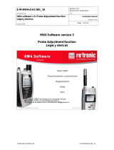
To open the housing of the
HygroLog, remove the five
screws, as indicated by the
arrows.
The far right drawing shows
the HygroClip S probe in the
retracted position. The base
of the probe is plugged into
a connector that is
separated from the main
board by a length of wire.
Probe
connector
The shorter screw
goes here

IN-E-HL-NT-V2_17
Rotronic AG
Bassersdorf, Switzerland
Document code
Unit
HygroLog HL-NT data logger:
instruction manual
Instruction Manual
Document Type
Page
10 of 75
Document title
© 2017; Rotronic AG IN-E-HL-NT-V2_17
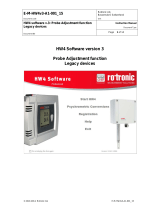
HygroClip S
extended position
Extension cable used to
separate the probe from
the HygroLog.
Ring
(replaces the slotted cap)

IN-E-HL-NT-V2_17
Rotronic AG
Bassersdorf, Switzerland
Document code
Unit
HygroLog HL-NT data logger:
instruction manual
Instruction Manual
Document Type
Page
11 of 75
Document title
© 2017; Rotronic AG IN-E-HL-NT-V2_17
Notes:
o For maximum protection against vandalism, use the HC2-S probe in the retracted position.
For a faster response, use the probe in the extended position.
o For additional information on the HygroClip 2 probes see document
E-M-HC2 Probes-V1.
2.3.2 Probe inputs 2 and 3 (HygroLog HL-NT3)
The HygroLog HL-NT3 can be used with up to 2 additional HygroClip 2 probes. For further
information on the HygroClip 2 probes, see document E-M-HC2 Probes-V1.
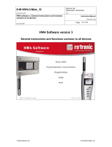
2.3.3 Connector identification
Input 1 (HygroClip 2 probe)
Input 2 (HygroClip 2 probe)
Input 3 (HygroClip 2 probe)
Input 1 (HygroClip 2 probe)
HL-NT2
HL-NT3

IN-E-HL-NT-V2_17
Rotronic AG
Bassersdorf, Switzerland
Document code
Unit
HygroLog HL-NT data logger:
instruction manual
Instruction Manual
Document Type
Page
12 of 75
Document title
© 2017; Rotronic AG IN-E-HL-NT-V2_17
2.4 Power supply
The HygroLog HL-NT ships with a regular 9V battery which must be inserted first (see battery
replacement).
To conserve battery power, models with the LC display and keypad are shipped with the Display
Sleep function enabled (see Software Functions). When the keypad has not been used for some
time, this function automatically turns off the display off. The display can be temporarily activated
by pressing on any key of the keypad.
When connected to a docking station, the HygroLog HL-NT can be powered with an external AC
adapter.
Note: most models of docking station require the use of an external AC adapter due to the current
consumption of the docking station internal electronics.
After reconfiguring the HygroLog HL-NT with the ROTRONIC HW4.software, a rechargeable
battery (accumulator) can be used instead of a regular battery. Recharging the battery require a
docking station and an external AC adapter.
WARNING: Trying to recharge a regular battery is potentially dangerous. Whenever a regular
battery is being used, the logger should be configured with the internal battery charge
function disabled.

IN-E-HL-NT-V2_17
Rotronic AG
Bassersdorf, Switzerland
Document code
Unit
HygroLog HL-NT data logger:
instruction manual
Instruction Manual
Document Type
Page
13 of 75
Document title
© 2017; Rotronic AG IN-E-HL-NT-V2_17
2.4.1 Battery lifetime
The battery lifetime depends on the manner in which the HygroLog HL-NT is being used. The
HygroLog HL-NT has a battery lifetime of one year when just one HygroClip probe is being used
(standard 500 mAh alkaline battery), when no docking station with internal electronics is connected
to the HygroLog HL-NT and when the logger is configured / programmed as follows:
Display Sleep function enabled (models with display)
No docking station with internal electronics
LED and beeper functions disabled
Log interval set to 15 minutes
Additional examples of battery lifetime (LED turned off, Logging active): in the following table, LCD
means that the LC display is permanently on (Display Sleep function disabled). No docking station
with internal electronics is connected to the HygroLog HL-NT.
Lifetime in days
Rechargeable
Battery
120mAh
Rechargeable
Battery
150mAh
Regular
Battery
500mAh
Regular
Battery
1000mAh
1 Probe / 5s Interval
2.7
3.4
11
22
1 Probe / 5s Interval / LCD
2.1
2.6
8.9
17
1 Probe / 1min Interval
14
17
59
118
1 Probe / 1min Interval / LCD
5.8
7.3
24
48
1 Probe / 15min Interval
89
111
372
744
1 Probe / 15min Interval / LCD
8.9
11
37
74
Note: the consumption of the display is negligible when the Display Sleep function is enabled. With
the display always on, power consumption is at its highest when the display refresh rate is set with
HW4 to the minimum of 5 sec.
Because of the requirement to keep track of the date and time, the HygroLog HL-NT does not have
a power on/off switch. Every minute, both the date and time are recorded to the internal EEPROM.
Seconds are not recorded. In the event of a relatively brief interruption of power (such as when
replacing the battery), time may fall behind in increments of one minute. Removing the battery for
an extended period of time will cause the logger to completely lose track of the date and time.

IN-E-HL-NT-V2_17
Rotronic AG
Bassersdorf, Switzerland
Document code
Unit
HygroLog HL-NT data logger:
instruction manual
Instruction Manual
Document Type
Page
14 of 75
Document title
© 2017; Rotronic AG IN-E-HL-NT-V2_17
2.4.2 Battery replacement
2.5 Memory card
The HygroLog HL-NT has a non-volatile 64 kb EEPROM internal memory that is used to save the
logger configuration data, the logger events and to temporarily hold measurement data.
The main memory is a plug-in flash memory card. As a standard, the HygroLog HL-NT ships with
a 64 MB card. This card allows the recording of up to 400,000 values in text file format (unprotected)
or up to 750,000 values in binary file format (protected). Memory cards with a capacity of up to 1
GB can be purchased from third parties. Regardless of its size, the flash memory card holds a
maximum of 512 files and directories, including one logger-configuration and one logger-event file.
The measurement data can be saved either to a file with extension XLS or to a file with extension
LOG. Files with XLS extension can be read with Notepad or imported into Microsoft Excel. Files
with extension LOG are encoded in binary format so as to prevent data manipulation and can only
be read with the ROTRONIC HW4 software. Both types of files can co-exist on the memory card.
The memory card can be removed from the logger and transferred to a card reader, a PDA, etc.
The flash memory card can also be read without being removed from the logger.
cover
To access the battery,
remove the screw shown
to the right and open the
rubber cover.
The battery is located at
the bottom of the
instrument.
battery

IN-E-HL-NT-V2_17
Rotronic AG
Bassersdorf, Switzerland
Document code
Unit
HygroLog HL-NT data logger:
instruction manual
Instruction Manual
Document Type
Page
15 of 75
Document title
© 2017; Rotronic AG IN-E-HL-NT-V2_17
2.6 LED Indicators
The HygroLog HL-NT is equipped with a green and red LED. The logger can be configured with
HW4 to have the green side of the LED flash when logging is active. The red side of the LED can
be made to flash when there is an alarm condition (see note below) and / or when the logger
requires attention (low battery, flash memory card full, etc.)
In the transient alarm mode, the red LED flashes for only as long as the data from a probe
corresponds to an alarm condition. In the durable alarm mode, the red LED stays on even after the
alarm condition has disappeared. When the LED is set to provide a durable alarm, it can be reset
from the keypad or with HW4.
2.7 Beeper
The HygroLog HL-NT is equipped with an internal beeper and can be configured with HW4 to make
a clicking sound when any key is being pressed. The beeper can also be configured to emit a 5-
second non-repeating sound when there is an alarm condition and / or when the logger requires
attention.
cover
memory
card
Memory Card:
To access the memory
card, remove the screw
shown to the right and pull
out the rubber cover.
The plug-in flash memory
card is located on top of
the main board.
screw

IN-E-HL-NT-V2_17
Rotronic AG
Bassersdorf, Switzerland
Document code
Unit
HygroLog HL-NT data logger:
instruction manual
Instruction Manual
Document Type
Page
16 of 75
Document title
© 2017; Rotronic AG IN-E-HL-NT-V2_17
2.8 HygroLog HL-NT functions
2.8.1 Calculated parameter
Using the HW4 software, the HygroLog HL-NT can be set to compute for each HygroClip probe
one of the following psychrometric parameters.
o Dew point (Dp)
o Frost point (Fp)
o Wet bulb temperature (Tw)
o Enthalpy (H)
o Vapor concentration (Dv)
o Specific humidity (Q)
o Mixing ratio by weight (R)
o Vapor concentration at saturation (Dvs)
o Vapor partial pressure (E)
o Vapor saturation pressure (Ew)
Each individual probe input can be associated with a different parameter.
Note: depending on whether dew point or frost point was selected, both the HygroLog HL-NT and
HW4 will display either the symbol Dp or the symbol Fp for values below freezing. The symbol Fp
indicates that the value is a frost point as opposed to being a dew point. Regardless of the dew
point / frost point selection, the symbol Dp is always displayed for values above freezing.
Some of the above parameters require barometric pressure as an input. When an analog pressure
probe is connected to one of the HygroLog HL-NT inputs, the logger can be set to use the
measurement from this probe. When no pressure probe is being used, a fixed pressure value can
be used. This value can be specified as part of the HygroLog HL-NT settings.

IN-E-HL-NT-V2_17
Rotronic AG
Bassersdorf, Switzerland
Document code
Unit
HygroLog HL-NT data logger:
instruction manual
Instruction Manual
Document Type
Page
17 of 75
Document title
© 2017; Rotronic AG IN-E-HL-NT-V2_17
2.8.2 Data logging
Data logging requires that a flash memory card be inserted inside the logger. Using the HW4
software, log files can be set to one of the following formats:
HW4 binary format [LOG]: files in this format are encoded and can be opened only with the
ROTRONIC HW4 software. HW4 does not allow any manipulation / alteration of the data
and requires a password to log in. Should the file be somehow modified, HW4 will give a
warning that the file is not an original.
Text file format [XLS]: in principle, files in this format can be opened with any text editor
and / or imported into Microsoft Excel.
The log file format is a global setting of the flash memory card (changing this setting requires the
HW4 software). At any given time, the card records data from all inputs in either one format or the
other. Files of different formats can co-exist in the flash memory card. Binary files (protected) use
substantially less memory space than text files (unprotected).
The logging function is independently activated for each individual input. The HygroLog HL-NT
creates a separate file for each input that is to be recorded. Multiple inputs cannot be recorded to
the same file. The HygroLog HL-NT automatically generates each file name. A file name consists
of 8 digits followed by the extension LOG or XLS. The first 4 digits are the same as the last 4 digits
of the logger serial number, the 5
th
digit is the same as the input number and the last 3 digits are a
number between 000 and 999 used to differentiate log files created for the same input. The last
number that was created is retained in the non-volatile EEPROM and is updated whenever a new
file is created for the input. When the number reaches 999, the next update will reset it to 000.
All files are located in the root directory of the flash memory card, including the logger event file
and the logger configuration file. Regardless of the memory card capacity, the root directory is
limited to a maximum of 250 files. This means that the memory card can hold a maximum of 248
log files, and that a card with this amount of files is considered to be full, even if all the memory has
not been used.

IN-E-HL-NT-V2_17
Rotronic AG
Bassersdorf, Switzerland
Document code
Unit
HygroLog HL-NT data logger:
instruction manual
Instruction Manual
Document Type
Page
18 of 75
Document title
© 2017; Rotronic AG IN-E-HL-NT-V2_17
Using HW4, the following log settings can be defined individually for each input:
Start date and time
Stop date and time
Log interval (minimum 5 seconds)
Measured values and computed parameter, or any parameter combination
User custom text (used for the log file header)
User name, HW4-ID, HW4 Serial Number
Automatic creation of a new file after 200,000 data points or at the end of each day, week
or month
Note: unlimited logging (loop mode logging) is not possible. Logging stops automatically when the
flash memory card is full. Prior to logging, the user may use HW4 to check the amount of free
memory, and verify that there is enough room available.
If the flash memory card is removed when logging is active, the HygroLog HL-NT will stop logging
until a new card is inserted. Unless the stop date and time have been reached, logging will start
again under the next available file name when a new card is inserted.
Warning: removing the memory card while logging is active may result in a corrupted log file and
in loss of data.
Logging can be started immediately for any individual input from the keypad of the HygroLog HL-
NT. A deferred start can only be programmed with the HW4 software. The green LED of the
HygroLog HL-NT can be set to flash when the instrument is recording data. To conserve battery
power, you may want to do this only when an external power source is being used.
Logging can be immediately stopped for any individual input directly from the keypad. With HW4,
logging can be stopped either immediately or at a future date and time for any individual input or
for all inputs.
When logging is ended, the HygroLog HL-NT returns to the measuring mode.

IN-E-HL-NT-V2_17
Rotronic AG
Bassersdorf, Switzerland
Document code
Unit
HygroLog HL-NT data logger:
instruction manual
Instruction Manual
Document Type
Page
19 of 75
Document title
© 2017; Rotronic AG IN-E-HL-NT-V2_17
2.8.3 Trend indicators
See also: Main operating modes and measurement interval
When the trend indicator function is enabled, a symbol appears on the left side of the LC display,
on the line corresponding to each measured or calculated value. An up arrow denotes a rising value
and a down arrow denotes a decreasing value. Both arrows denote a stable value.
The trend of a parameter is evaluated by comparing successive averages made of 6 values each.
With the shortest possible measurement interval of 5 seconds, each average covers a time period
of 30 seconds and the first indication of a trend is available after one minute. Subsequently, the
trend is evaluated and updated every 30 seconds. With a longer measurement interval, each
average is computed over a longer period of time (always using 6 values) and the trend is also
updated over longer intervals of time.
For any measured or calculated parameter, the trend indicator shows a stable condition when the
absolute value of the difference between two successive averages is < 0.02.
2.8.4 Alarm function
Using the HW4 software, both a high and a low alarm value can be associated with the humidity,
temperature and calculated parameter of each probe input, A hysteresis value can also be entered
for each parameter. This value is used for both the low and the high alarm conditions.
The HygroLog HL-NT has a red LED which can be set with HW4 to flash whenever the value of
any parameter corresponds to an alarm condition. The LED can be set to flash only as long as the
alarm condition exits or it can be set to provide a durable alarm and, in this case, it will to keep
flashing until the alarm is reset.
The HygroLog HL-NT can also be set with HW4 to beep for 5 seconds when there is an alarm
condition. The HygroLog HL-NT will beep only once, when the condition occurs.
Log files do not record the existence of an alarm condition. However, when the contents of a log
file are viewed as a data table with the HW4 software, values that correspond to an alarm condition

IN-E-HL-NT-V2_17
Rotronic AG
Bassersdorf, Switzerland
Document code
Unit
HygroLog HL-NT data logger:
instruction manual
Instruction Manual
Document Type
Page
20 of 75
Document title
© 2017; Rotronic AG IN-E-HL-NT-V2_17
are printed over a red background, based on the alarm settings that HW4 downloaded from the
logger.
2.8.5 Display-Sleep function
This function can be enabled and configured only with the HW4 software.
Using the Display Sleep function can substantially extend the lifetime of the battery. When the
Display Sleep function is active, the LC display of the HygroLog HL-NT stays blank. The Display
Sleep function is effective both in the measure and in the record mode.
The display of the HygroLog HL-NT can be set to be always on. It can also be set to automatically
go blank after 30 seconds, 1, 5, 10 or 20 minutes when no key is being pressed or when there is
no communication with a PC. If the HygroClip NT was in the function menu at the time the display
goes blank, it automatically exits the menu.
The HygroLog suspends the Display Sleep function whenever a key is pressed. The function is
also suspended when external power is available or when the logger receives a communication
request (for example from a PC
1
). When the display comes up again, it shows by default the
measurements from the probe that was selected last.
1
When the HygroLog HL-NT is connected by means of a docking station to a PC and HW4
is running, you should use an external AC adapter to power both the HygroLog HL-NT and
docking station. HW4 can be set to use a polling interval as short as 5 seconds to interrogate all
instruments connected to the PC and this could cause the battery life time to be sharply reduced.
/