
E
n
AV Receiver
TX-SR607
Instruction Manual
Thank you for purchasing an Onkyo AV Receiver.
Please read this manual thoroughly before making
connections and plugging in the unit.
Following the instructions in this manual will enable
you to obtain optimum performance and listening
enjoyment from your new AV Receiver.
Please retain this manual for future reference.
Contents
Introduction ...................................2
Connection ..................................15
Turning On & First Time Setup
.....38
Basic Operations.........................51
Using the Listening Modes ........62
Advanced Setup ..........................69
Zone 2 .........................................85
Controlling Other Components
....89
Others.........................................100

2
Important Safety Instructions
1. Read these instructions.
2. Keep these instructions.
3. Heed all warnings.
4. Follow all instructions.
5. Do not use this apparatus near water.
6. Clean only with dry cloth.
7. Do not block any ventilation openings. Install in
accordance with the manufacturer’s instructions.
8. Do not install near any heat sources such as radia-
tors, heat registers, stoves, or other apparatus
(including amplifiers) that produce heat.
9. Do not defeat the safety purpose of the polarized or
grounding-type plug. A polarized plug has two
blades with one wider than the other. A grounding
type plug has two blades and a third grounding
prong. The wide blade or the third prong are pro-
vided for your safety. If the provided plug does not
fit into your outlet, consult an electrician for
replacement of the obsolete outlet.
10. Protect the power cord from being walked on or
pinched particularly at plugs, convenience recepta-
cles, and the point where they exit from the appara-
tus.
11. Only use attachments/accessories specified by the
manufacturer.
12. Use only with the cart, stand,
tripod, bracket, or table spec-
ified by the manufacturer, or
sold with the apparatus.
When a cart is used, use cau-
tion when moving the cart/
apparatus combination to
avoid injury from tip-over.
13. Unplug this apparatus during lightning storms or
when unused for long periods of time.
14. Refer all servicing to qualified service personnel.
Servicing is required when the apparatus has been
damaged in any way, such as power-supply cord or
plug is damaged, liquid has been spilled or objects
have fallen into the apparatus, the apparatus has
been exposed to rain or moisture, does not operate
normally, or has been dropped.
15. Damage Requiring Service
Unplug the apparatus from the wall outlet and refer
servicing to qualified service personnel under the
following conditions:
A. When the power-supply cord or plug is dam-
aged,
B. If liquid has been spilled, or objects have fallen
into the apparatus,
C. If the apparatus has been exposed to rain or
water,
D. If the apparatus does not operate normally by
following the operating instructions. Adjust
only those controls that are covered by the oper-
ating instructions as an improper adjustment of
other controls may result in damage and will
often require extensive work by a qualified tech-
nician to restore the apparatus to its normal
operation,
E. If the apparatus has been dropped or damaged in
any way, and
F. When the apparatus exhibits a distinct change in
performance this indicates a need for service.
16. Object and Liquid Entry
Never push objects of any kind into the apparatus
through openings as they may touch dangerous volt-
age points or short-out parts that could result in a
fire or electric shock.
The apparatus shall not be exposed to dripping or
splashing and no objects filled with liquids, such as
vases shall be placed on the apparatus.
Don’t put candles or other burning objects on top of
this unit.
17. Batteries
Always consider the environmental issues and fol-
low local regulations when disposing of batteries.
18. If you install the apparatus in a built-in installation,
such as a bookcase or rack, ensure that there is ade-
quate ventilation.
Leave 20 cm (8") of free space at the top and sides
and 10 cm (4") at the rear. The rear edge of the shelf
or board above the apparatus shall be set 10 cm (4")
away from the rear panel or wall, creating a flue-
like gap for warm air to escape.
WARNING:
TO REDUCE THE RISK OF FIRE OR ELECTRIC
SHOCK, DO NOT EXPOSE THIS APPARATUS TO
RAIN OR MOISTURE.
CAUTION:
TO REDUCE THE RISK OF ELECTRIC SHOCK,
DO NOT REMOVE COVER (OR BACK). NO
USER-SERVICEABLE PARTS INSIDE. REFER
SERVICING TO QUALIFIED SERVICE
PERSONNEL.
The lightning flash with arrowhead symbol, within an
equilateral triangle, is intended to alert the user to the
presence of uninsulated “dangerous voltage” within
the product’s enclosure that may be of sufficient
magnitude to constitute a risk of electric shock to
persons.
The exclamation point within an equilateral triangle is
intended to alert the user to the presence of important
operating and maintenance (servicing) instructions in
the literature accompanying the appliance.
WARNING
RISK OF ELECTRIC SHOCK
DO NOT OPEN
RISQUE DE CHOC ELECTRIQUE
NE PAS
OUVRIR
AVIS
PORTABLE CART WARNIN
G
S3125A

3
Precautions
1. Recording Copyright—Unless it’s for personal use
only, recording copyrighted material is illegal with-
out the permission of the copyright holder.
2. AC Fuse—The AC fuse inside the unit is not user-
serviceable. If you cannot turn on the unit, contact
your Onkyo dealer.
3. Care—Occasionally you should dust the unit all
over with a soft cloth. For stubborn stains, use a soft
cloth dampened with a weak solution of mild deter-
gent and water. Dry the unit immediately afterwards
with a clean cloth. Don’t use abrasive cloths, thin-
ners, alcohol, or other chemical solvents, because
they may damage the finish or remove the panel let-
tering.
4. Power
WARNING
BEFORE PLUGGING IN THE UNIT FOR THE
FIRST TIME, READ THE FOLLOWING SEC-
TION CAREFULLY.
AC outlet voltages vary from country to country.
Make sure that the voltage in your area meets the
voltage requirements printed on the unit’s rear panel
(e.g., AC 230 V, 50 Hz or AC 120 V, 60 Hz).
The power cord plug is used to disconnect this unit
from the AC power source. Make sure that the plug
is readily operable (easily accessible) at all times.
Pressing the [ON/STANDBY] button to select
Standby mode does not fully shutdown the unit. If
you do not intend to use the unit for an extended
period, remove the power cord from the AC outlet.
5. Preventing Hearing Loss
Caution
Excessive sound pressure from earphones and head-
phones can cause hearing loss.
6. Batteries and Heat Exposure
Warning
Batteries (battery pack or batteries installed) shall
not be exposed to excessive heat as sunshine, fire or
the like.
7. Never Touch this Unit with Wet Hands—Never
handle this unit or its power cord while your hands
are wet or damp. If water or any other liquid gets
inside this unit, have it checked by your Onkyo
dealer.
8. Handling Notes
• If you need to transport this unit, use the original
packaging to pack it how it was when you origi-
nally bought it.
• Do not leave rubber or plastic items on this unit
for a long time, because they may leave marks on
the case.
• This unit’s top and rear panels may get warm
after prolonged use. This is normal.
• If you do not use this unit for a long time, it may
not work properly the next time you turn it on, so
be sure to use it occasionally.
For U.S. models
FCC Information for User
CAUTION:
The user changes or modifications not expressly
approved by the party responsible for compliance could
void the user’s authority to operate the equipment.
NOTE:
This equipment has been tested and found to comply
with the limits for a Class B digital device, pursuant to
Part 15 of the FCC Rules. These limits are designed to
provide reasonable protection against harmful interfer-
ence in a residential installation.
This equipment generates, uses and can radiate radio fre-
quency energy and, if not installed and used in accor-
dance with the instructions, may cause harmful
interference to radio communications. However, there is
no guarantee that interference will not occur in a partic-
ular installation. If this equipment does cause harmful
interference to radio or television reception, which can
be determined by turning the equipment off and on, the
user is encouraged to try to correct the interference by
one or more of the following measures:
• Reorient or relocate the receiving antenna.
• Increase the separation between the equipment and
receiver.
• Connect the equipment into an outlet on a circuit dif-
ferent from that to which the receiver is connected.
• Consult the dealer or an experienced radio/TV techni-
cian for help.
For Canadian Models
NOTE: THIS CLASS B DIGITAL APPARATUS
COMPLIES WITH CANADIAN ICES-003.
For models having a power cord with a polarized plug:
CAUTION: TO PREVENT ELECTRIC SHOCK,
MATCH WIDE BLADE OF PLUG TO WIDE SLOT,
FULLY INSERT.
Modèle pour les Canadien
REMARQUE: CET APPAREIL NUMÉRIQUE DE
LA CLASSE B EST CONFORME À LA NORME
NMB-003 DU CANADA.
Sur les modèles dont la fiche est polarisée:
ATTENTION: POUR ÉVITER LES CHOCS ÉLEC-
TRIQUES, INTRODUIRE LA LAME LA PLUS
LARGE DE LA FICHE DANS LA BORNE CORRE-
SPONDANTE DE LA PRISE ET POUSSER
JUSQU’AU FOND.

4
Precautions—Continued
For British models
Replacement and mounting of an AC plug on the power
supply cord of this unit should be performed only by
qualified service personnel.
IMPORTANT
The wires in the mains lead are coloured in accordance
with the following code:
Blue: Neutral
Brown: Live
As the colours of the wires in the mains lead of this appa-
ratus may not correspond with the coloured markings
identifying the terminals in your plug, proceed as fol-
lows:
The wire which is coloured blue must be connected to
the terminal which is marked with the letter N or
coloured black.
The wire which is coloured brown must be connected to
the terminal which is marked with the letter L or
coloured red.
IMPORTANT
The plug is fitted with an appropriate fuse. If the fuse
needs to be replaced, the replacement fuse must
approved by ASTA or BSI to BS1362 and have the same
ampere rating as that indicated on the plug. Check for the
ASTA mark or the BSI mark on the body of the fuse.
If the power cord’s plug is not suitable for your socket
outlets, cut it off and fit a suitable plug. Fit a suitable fuse
in the plug.
For European Models
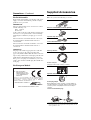
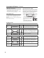
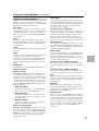
Supplied Accessories
Make sure you have the following accessories:
* In catalogs and on packaging, the letter at the end of the product
name indicates the color. Specifications and operations are the
same regardless of color.
Declaration of Conformity
We,
ONKYO EUROPE
ELECTRONICS GmbH
LIEGNITZERSTRASSE 6,
82194 GROEBENZELL,
GERMANY
GROEBENZELL, GERMANY
ONKYO EUROPE ELECTRONICS GmbH
K. MIYAGI
declare in own responsibility, that the ONKYO product
described in this instruction manual is in compliance with the
corresponding technical standards such as EN60065,
EN55013, EN55020 and EN61000-3-2, -3-3.
Remote controller & two batteries (AA/R6)
Speaker setup microphone
Indoor FM antenna
AM loop antenna
Power cord (on some model)
(Plug type varies from country to country.)
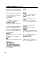
Speaker cable labels
Power-plug adapter
Only supplied in certain countries. Use this adapter if
your AC outlet does not match with the plug on the AV
receiver’s power cord (adapter varies from country to
country).
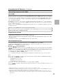
*How to mount the AC plug:
3
2
1
Speaker Cable
FRONT
LEFT
FRONT
LEFT
FRONT
RIGHT
FRONT
RIGHT
SURROUND BACK
RIGHT
SURROUND BACK
RIGHT
FRONT HIGH
LEFT
FRONT HIGH
LEFT
FRONT HIGH
RIGHT
FRONT HIGH
RIGHT
FRONT
LEFT
FRONT
LEFT
FRONT
RIGHT
FRONT
RIGHT
SURROUND
LEFT
SURROUND
LEFT
SURROUND
RIGHT
SURROUND
RIGHT
SURROUND
LEFT
SURROUND
LEFT
SURROUND
RIGHT
SURROUND
RIGHT
SURROUND BACK
RIGHT
SURROUND BACK
RIGHT
CENTER
CENTER
CENTER
CENTER
SURROUND BACK
LEFT
SURROUND BACK
LEFT
SURROUND BACK
LEFT
SURROUND BACK
LEFT
FRONT HIGH
LEFT
FRONT HIGH
LEFT
FRONT HIGH
RIGHT
FRONT HIGH
RIGHT
FRONT WIDE
LEFT
FRONT WIDE
LEFT
FRONT WIDE
RIGHT
FRONT WIDE
RIGHT
FRONT WIDE
LEFT
FRONT WIDE
LEFT
FRONT WIDE
RIGHT
FRONT WIDE
RIGHT
SP-B/ZONE2
LEFT
SP-B/ZONE2
LEFT
SP-B/ZONE2
RIGHT
SP-B/ZONE2
RIGHT
SP-B/ZONE2
LEFT
SP-B/ZONE2
LEFT
SP-B/ZONE2
RIGHT
SP-B/ZONE2
RIGHT
*

5
Features
Amplifier
• 90 Watts/Channel @ 8 ohms (FTC)
• 140 Watts/Channel @ 6 ohms (IEC)
• 175 Watts/Channel @ 6 ohms (JEITA)
• WRAT-Wide Range Amplifier Technology
(5 Hz-100 kHz bandwidth)
• Optimum Gain Volume Circuitry
• H.C.P.S. (High Current Power Supply) Massive High
Power Transformer
Processing
• HDMI Video Upscaling (to 1080i Compatible) with
Faroudja DCDi Edge Enhancement
• HDMI ver.1.3a with Repeater System (Deep Color,
x.v.Color, Lip Sync, DTS
*2
-HD Master Audio,
DTS-HD High Resolution Audio, Dolby TrueHD
*1
,
Dolby Digital Plus, SA-CD and Multi-CH PCM)
• Dolby Pro Logic IIz (with “Front High” Direction
Mode)
• DTS Surround Sensation Speaker Technology
*2
• Non-Scaling Configuration
• Direct Mode and Pure Audio Mode
• Music Optimizer
*8
for Compressed Music
• 192 kHz/24-bit D/A Converters
• Powerful and Highly Accurate 32-bit DSP Processing
x 2
Connections
• 6 HDMI
*3
Inputs (1 on front panel) and 1 Output
• Onkyo for System Control
• 4 Digital Inputs (2 Optical / 2 Coaxial)
• Component Video Switching (2 Inputs/1 Output)
• Front “Portable” Input for iPod and MP3 Players
• Universal Port for the Dock for iPod/HD Radio
*5
Dock (North American models) / DAB+ (European
models)
• Dual Subwoofer Pre Out
• Banana Plug-Compatible Speaker Posts
*4
• Powered Zone 2
• Bi-Amp Connectable for FL/FR with SBL/SBR
Miscellaneous
• 40 SIRIUS
*6
/AM/FM Presets (North American mod-
els)
• 40 AM/FM Presets (European and Asian models)
• Audyssey 2EQ
™*7
to Correct Room Acoustic Prob-
lems
• Audyssey Dynamic EQ
™*7
for Loudness Correction
• Audyssey Dynamic Volume
™*7
to Maintain Optimal
Listening Level and Dynamic Range
• Crossover Adjustment
(40/50/60/80/100/120/150/200 Hz)
• A/V Sync Control Function (up to 100 ms)
• On-Screen Display via HDMI
• Aluminum Front Panel
• Preprogrammed (with On-Screen Display Set-up)
-Compatible Remote
*1.
Manufactured under license from Dolby Laboratories. “Dolby”,
“Pro Logic” and the double-D symbol are trademarks of Dolby
Laboratories.
*2.
Manufactured under license under U.S. Patent #’s: 5,451,942;
5,956,674; 5,974,380; 5,978,762; 6,226,616; 6,487,535;
7,212,872; 7,333,929; 7,392,195; 7,272,567 & other U.S. and
worldwide patents issued & pending. DTS is a registered trade-
mark & the DTS logos, Symbol, DTS-HD Master Audio and
DTS Surround Sensation are trademarks of DTS, Inc.
©1996-2008 DTS, Inc. All Rights Reserved.
*3.
HDMI, the HDMI logo and High Definition Multimedia Inter-
face are trademarks or registered trademarks of HDMI Licens-
ing, LLC.
*4. In Europe, using banana plugs to connect speakers to an audio
amplifier is prohibited.
*5.
The HD Radio Ready logo is a proprietary trademark of iBiquity
Digital Corp.
*6.
SIRIUS, XM and all related marks and logos are trademarks of
Sirius XM Radio Inc. and its subsidiaries. All other marks and
logos are the property of their respective owners. All rights
reserved. SIRIUS subscription sold separately. Taxes and a one-
time activation fee may apply. SIRIUS tuner required (sold sep-
arately) to receive the SIRIUS service. All programming and
fees subject to change. It is prohibited to copy, decompile, dis-
assemble, reverse engineer, hack, manipulate or otherwise make
available any technology or software incorporated in receivers
compatible with the SIRIUS Satellite Radio System. Service not
available in Alaska or Hawaii.
*7.
Manufactured under license from Audyssey Laboratories. U.S.
and foreign patents pending. Audyssey 2EQ
™
,
Audyssey Dynamic Volume
™
and Audyssey Dynamic EQ
™
are trademarks of Audyssey Laboratories.
*8. Music Optimizer™ is a trademark of Onkyo Corporation.
* Apple and iPod are trademarks of Apple Inc., registered in the
U.S. and other countries.
* “x.v.Color” is a trademark of Sony Corporation.
This product incorporates copyright protection technology that
is protected by U.S. patents and other intellectual property
rights. Use of this copyright protection technology must be
authorized by Macrovision Corporation, and is intended for
home and other limited consumer uses only unless otherwise
authorized by Macrovision. Reverse engineering or disassem-
bly is prohibited.

6
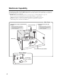
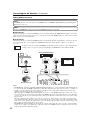
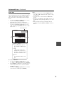
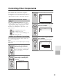
Multiroom Capability
You can use two speaker systems with this AV receiver—a surround-sound speaker system (up to 7.1 channels) in
your main listening room, a stereo speaker system in a second room, or Zone 2, as we call it. And, you can select a
different audio source for each room.
Main Room: In your main listening room, you can enjoy up to 7.1-channel playback (see page 15).
You can enjoy the various listening modes such as Dolby and DTS (see pages 62-68).
* While Powered Zone 2 is being used, playback is reduced to 5.1-channels (see page 85).
Zone 2: In your Zone 2 room, you can enjoy 2-channel stereo playback (see page 85).
* The listening modes cannot be used with Zone 2.
Surround back left and right
speakers
* While Powered Zone 2 is being
used, nothing is output by these
speakers (page 86).
Main Room
Front left and right
speakers
Center speaker
Surround left and right speakers
Subwoofer
Zone 2 Room
Left and right
stereo speakers
Front high left and right
speakers
* While Powered Zone 2 is being
used, nothing is output by these
speakers (page 86).

7
Contents
Introduction
Important Safety Instructions .................................... 2
Precautions ............................................................... 3
Supplied Accessories................................................ 4
Features .................................................................... 5
Multiroom Capability.................................................. 6
Front & Rear Panels.................................................. 8
Front Panel............................................................ 8
Display................................................................. 10
Rear Panel .......................................................... 11
Remote Controller ................................................... 13
Installing the Batteries ......................................... 13
Aiming the Remote Controller ............................. 13
Controlling the AV Receiver ................................ 14
Connection
About Home Theater............................................... 15
Enjoying Home Theater....................................... 15
Connecting the AV Receiver ................................... 16
Connecting Your Speakers ................................. 16
Bi-amping the Front Speakers............................. 19
Connecting Antenna............................................ 20
About AV Connections ........................................ 22
Connecting Components with HDMI ................... 23
Connecting Both Audio & Video .......................... 25
Which Connections Should I Use?...................... 25
Connecting a TV or Projector .............................. 27
Connecting a DVD Player ................................... 28
Connecting a VCR or DVD Recorder for Playback
..... 29
Connecting a VCR or DVD Recorder for Recording
.... 30
Connecting a Satellite, Cable, Terrestrial
Set-top box, or Other Video Source.................. 31
Connecting a Game Console .............................. 32
Connecting a Camcorder or Other Device .......... 33
Connecting a Portable Audio player.................... 33
Connecting a CD Player or Turntable ................. 34
Connecting a Cassette, CDR, MiniDisc,
or DAT Recorder............................................... 35
Connecting an RI Dock ....................................... 36
Connecting a Dock with the Universal Port
connector .......................................................... 36
Connecting Onkyo Components ................... 37
Connecting the Power Cord ................................ 37
Turning On & First Time Setup
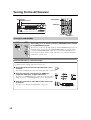
Turning On the AV Receiver ................................... 38
Turning On and Standby ..................................... 38
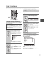
First Time Setup...................................................... 39
Using the Onscreen Setup Menus ...................... 39
Using the Display to change the settings ............ 39
Video Input Setup................................................ 40
Digital Input Setup ............................................... 42
Speaker Settings ................................................. 43
TV Format Setup (not North American models)
..... 44
FM/AM Frequency Step Setup (on some models)
.... 44
Changing the Input Display ................................. 45
Audyssey 2EQ™ Room Correction and
Speaker Setup .................................................. 46
Basic Operations
Basic Operations..................................................... 51
Selecting the Input Source .................................. 51
Adjusting the Bass & Treble................................ 52
Displaying Source Information ............................ 52
Setting the Display Brightness ............................ 52
Muting the AV receiver ........................................ 53
Using the Sleep Timer......................................... 53
Using Headphones.............................................. 53
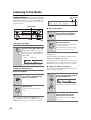
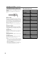
Listening to the Radio.............................................. 54
Using the Tuner ................................................... 54
Presetting AM/FM Stations.................................. 55
Using RDS (European models only).................... 56
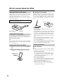
UP-A1 series Dock for iPod..................................... 58
About the UP-A1 series Dock.............................. 58
Compatible iPod models...................................... 58
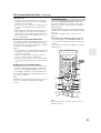
Putting Your iPod in the Dock.............................. 58
Function Overview............................................... 58
Controlling iPod ................................................... 59
Recording ................................................................ 61
Using the Listening Modes
Using the Listening Modes ...................................... 62
Selecting Listening Modes................................... 62
Listening Modes Available for Each Source Format
..... 63
About the Listening Modes .................................. 67
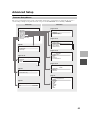
Advanced Setup
Advanced Setup ...................................................... 69
Onscreen Setup Menus....................................... 69
Common Procedures in Setup Menu .................. 70
Speaker Setup..................................................... 70
Audio Adjust ........................................................ 73
Using the Audio Settings ..................................... 75
Assigning Listening Modes to Input Sources....... 77
Source Setup....................................................... 78
Miscellaneous (Volume/OSD) Setup ................... 80
Hardware Setup................................................... 81
Lock Setup........................................................... 83
Using the Video Settings ..................................... 83
Digital Input Signal Formats ................................ 84
Zone 2
Zone 2 ..................................................................... 85
Connecting Zone 2 .............................................. 85
Setting the Powered Zone 2 ................................ 86
Using Zone 2 ....................................................... 87
Controlling Other Components
Controlling Other Components................................ 89
Preprogrammed Remote Control Codes ............. 89
Looking up for Remote Control Code .................. 89
Entering Remote Control Codes.......................... 91
Remote Control Codes for Onkyo Components
Connected via ............................................. 92
Resetting REMOTE MODE Buttons .................... 92
Resetting the Remote Controller ......................... 92
Controlling a TV................................................... 93
Controlling a DVD Player, or DVD Recorder ....... 94
Controlling a VCR or PVR ................................... 95
Controlling a Satellite Receiver or Cable Receiver
....... 96
Controlling a CD Player, CD Recorder, or MD Player
... 97
Controlling an RI Dock......................................... 98
Controlling a Cassette Recorder ......................... 99
Others
Troubleshooting..................................................... 100
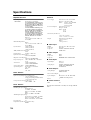
Specifications ........................................................ 104
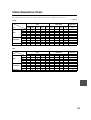
Video Resolution Chart ......................................... 105
*
To reset the AV receiver to its factory defaults, turn it
on and, while holding down the [VCR/DVR] button,
press the [ON/STANDBY] button (see page 100).

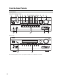
8
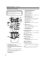
Front & Rear Panels
North American/Taiwan models
Other models
The actual front panel has various logos printed on it. They are not shown here for clarity.
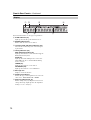
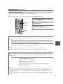
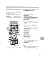
Front Panel

9
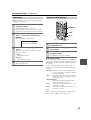
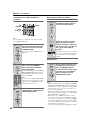
Front & Rear Panels—Continued
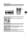
The page numbers in parentheses show where you can find the main explanation for each item.
ON/STANDBY button (38)
This button is used to set the AV receiver to On or
Standby.
STANDBY indicator (38)
This indicator lights up when the AV receiver is in
Standby mode, and it flashes while a signal is being
received from the remote controller.
ZONE 2 indicator (87)
This indicator lights up when Zone 2 is selected.
ZONE 2 LEVEL/TONE LEVEL buttons
ZONE 2 and OFF buttons (87)
The [ZONE 2] button is used to select the input
source for Zone 2.
The [OFF] button is used to turn off the output of
Zone 2.
[–] & [+] buttons (52, 88)
Used to adjust the tone (bass and treble) and the vol-
ume level of Zone 2.
TONE button (52)
Used to select either bass or treble.
Remote control sensor (13)
This sensor receives control signals from the remote
controller.
Display
See “Display” on page 10.
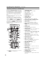
MOVIE/TV button (62)
Selects the listening modes intended for use with
movies and TV.
MUSIC button (62)
Selects the listening modes intended for use with
music.
GAME button (62)
Selects the listening modes intended for use with
video games.
DIMMER or RT/PTY/TP button (52, 57)
This button is used to adjust the display brightness.
On the European model, this is the [RT/PTY/TP]
button, and it’s for RDS (Radio Data System). See
“Using RDS (European models only)” on page 56.
MEMORY button (55)
This button is used when storing or deleting radio
presets.
TUNING MODE button (54)
This button is used to select the Auto or Manual
tuning mode.
DISPLAY button (52)
This button is used to display various information
about the currently selected input source.
SETUP button
This button is used to access the onscreen setup
menus that appear on the connected TV.
Arrow, TUNING, PRESET and ENTER
buttons
When the AM or FM input source is selected, the
TUNING [ ]/[ ] buttons are used to tune the tuner,
and the PRESET [ ]/[ ] buttons are used to select
radio presets (see page 55).
When the onscreen setup menus are used, they work
as arrow buttons and are used to select and set
items. The [ENTER] button is also used with the
onscreen setup menus.
RETURN button
This button is used to return to the previously dis-
played onscreen setup menu.
MASTER VOLUME control (51)
This control is used to adjust the volume of the AV
receiver to Min, 1 through 79 or Max.
PHONES jack (53)
This 1/4-inch phone jack is for connecting a stan-
dard pair of stereo headphones for private listening.
AUX INPUT HDMI (24)
Used to connect a HD camcorder etc.
Input selector buttons (51)
These buttons are used to select from the following
input sources: DVD/BD, VCR/DVR, CBL/SAT,
GAME, AUX, TV/TAPE, TUNER, CD, PORT.
AUX INPUT
This input can be used to connect a camcorder,
game console, and so on. There are jacks for com-
posite video, and analog audio.
PORTABLE (33):
Used to connect a portable Audio Player.
SETUP MIC jack (46)
The Audyssey 2EQ™ Room Correction and
Speaker Setup microphone connects here.
PURE AUDIO button and indicator (62)
On models other than the North American / Taiwan
models, selects the Pure Audio listening mode. The
indicator lights up when this mode is selected.
Pressing this button again selects the previous lis-
tening mode.

10
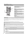
Front & Rear Panels—Continued
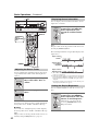
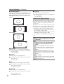
For detailed information, see the pages in parentheses.
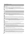
SLEEP indicator (53)
Lights up when the Sleep function has been set.
MUTING indicator (53)
Flashes while the AV receiver is muted.
Listening mode and format indicators (62)
Show the selected listening mode and audio input
signal format.
Tuning indicators (54)
RDS (European models) (56):
Lights up when tuned to a radio station that supports
RDS (Radio Data System).
AUTO (54):
Lights up when Auto Tuning mode is selected for
AM or FM radio. Goes off when Manual Tuning
mode is selected.
TUNED (54):
Lights up when tuned to a radio station.
FM STEREO (54):
Lights up when tuned to a stereo FM station.
Message area
Displays various information.
Audio input indicators
Indicate the type of audio input that’s selected as the
audio source: PCM, MULTI CH, or HDMI.
Audyssey indicator (46, 72)
Flashes during Audyssey 2EQ™ Room Correction
and Speaker Setup. Lights up when the “Equalizer
Settings” is set to “Audyssey”.
Display

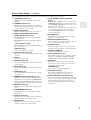
11
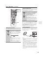
Front & Rear Panels—Continued
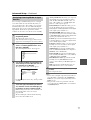
North American/Taiwan models
Other models
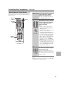
On some model
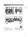
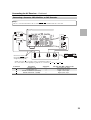
DIGITAL IN COAXIAL 1 and 2
These coaxial digital audio inputs are for connect-
ing components with coaxial digital audio outputs,
such as CD and DVD players. They’re assignable,
which means you can assign each one to an input
selector to suit your setup. See “Digital Input
Setup” on page 42.
DIGITAL IN OPTICAL 1 and 2
These optical digital audio inputs are for connecting
components with optical digital audio outputs, such
as CD and DVD players. They’re assignable, which
means you can assign each one to an input selector
to suit your setup. See “Digital Input Setup” on
page 42.
Rear Panel

12
Front & Rear Panels—Continued
COMPONENT VIDEO IN 1 and 2
These RCA component video inputs are for con-
necting components with a component video out-
put, such as a DVD player, DVD recorder, or DVR
(digital video recorder). They’re assignable, which
means you can assign each one to an input selector
to suit your setup. See “Component Video Setup”
on page 41.
COMPONENT VIDEO OUT
This RCA component video output is for connect-
ing a TV or projector with a component video input.
HDMI IN 1–5 and OUT
HDMI (High Definition Multimedia Interface) con-
nections carry digital audio and digital video.
The HDMI inputs are for connecting components
with an HDMI output, such as a DVD player, Blu-
ray Disc Player, DVD recorder, or DVR (digital
video recorder). They’re assignable, which means
you can assign each one to an input selector to suit
your setup. See “HDMI Input Setup” on page 40.
The HDMI output is for connecting a TV or projec-
tor with an HDMI input.
FM ANTENNA
This jack is for connecting an FM antenna.
AM ANTENNA
These push terminals are for connecting an AM
antenna.
MONITOR OUT V
The composite video jack should be connected to a
video input on your TV or projector.
UNIVERSAL PORT (36)
This jack is for connecting the component with the
Universal Port connector such as UP-A1 series
Dock.
FRONT L/R, CENTER, SURR L/R, and SURR
BACK L/R speakers
These terminal posts are for connecting the front
L/R, center, surround L/R, and surround back L/R
speakers.
The FRONT L/R and SURR BACK L/R terminal
posts can be used with front speakers and surround
back speakers respectively, or used to bi-amp the
front speakers. See “Bi-amping the Front Speakers”
on page 19”.
The SURR BACK L/R terminals can be used to
connect the front high L/R speakers.
REMOTE CONTROL
This (Remote Interactive) jack can be con-
nected to an jack on another Onkyo AV compo-
nent. The AV receiver’s remote controller can then
be used to control that component. To use , you
must make an analog audio connection (RCA)
between the AV receiver and the other AV compo-
nent, even if they are connected digitally.
SIRIUS antenna (North American models
only)
This jack is for connecting a SIRIUS Satellite Radio
antenna, sold separately (see the separate SIRIUS
instructions).
CD IN
This analog audio input is for connecting a CD
player’s analog audio output.
TV/TAPE IN/OUT
This analog audio input and output are for connect-
ing a recorder with an analog audio input and output
(cassette, Mini Disc, etc.).
GAME IN
Here you can connect a game console, etc. Input
jacks include composite video and analog audio.
CBL/SAT IN
Here you can connect a cable/satellite receiver, set-
top box, etc. Input jacks include composite video
and analog audio.
VCR/DVR IN/OUT
Here you can connect a VCR or DVR (digital video
recorder). Input and output jacks include composite
video and analog audio.
DVD/BD IN
Here you can connect a DVD/BD player. Input
jacks include composite video and analog audio.
You can connect a DVD/BD player’s 2-channel ana-
log audio output.
ZONE 2 LINE OUT L/R
This analog audio output can be connected to a line
input on an integrated amplifier in Zone 2. See
“Connecting Zone 2” on page 85.
PRE OUT: SUBWOOFER
This analog audio outputs can be connected to a
powered subwoofer. The same signal is output from
each jack.
FRONT HIGH L/R speakers
These terminals are for connecting the front high
L/R speakers.
The FRONT HIGH L/R terminal can be used with
front high speakers respectively, or used to connect
the speakers in Zone 2.
See “Connecting Zone 2” on page 85.
AC INLET (On some model)
The supplied power cord is connected here. The
other end of the power cord should be connected to
a suitable wall outlet.
See pages 15-37 for connection information.

13
Remote Controller
Notes:
• If the remote controller doesn’t work reliably, try
replacing the batteries.
• Don’t mix new and old batteries or different types of
batteries.
• If you intend not to use the remote controller for a long
time, remove the batteries to prevent damage from
leakage or corrosion.
• Expired batteries should be removed as soon as possi-
ble to prevent damage from leakage or corrosion.
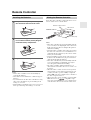
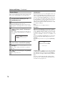
To use the remote controller, point it at the AV receiver’s
remote control sensor, as shown below.
Notes:
• The remote controller may not work reliably if the AV
receiver is subjected to bright light, such as direct sun-
light or inverter-type fluorescent lights. Keep this in
mind when installing.
• If another remote controller of the same type is used in
the same room, or the AV receiver is installed close to
equipment that uses infrared rays, the remote control-
ler may not work reliably.
• Don’t put anything, such as a book, on the remote con-
troller, because the buttons may be pressed inadvert-
ently, thereby draining the batteries.
• The remote controller may not work reliably if the AV
receiver is installed in a rack behind colored glass
doors. Keep this in mind when installing.
• The remote controller will not work if there’s an
obstacle between it and the AV receiver’s remote con-
trol sensor.
• When the remote control codes have been registered
and you want to operate another component (page 89),
or when you want to operate an Onkyo component
without connection, point the remote controller at
the other component to use it.
• When you want to operate an Onkyo component with
connection or an -compatible compo-
nent connected via HDMI (page 93), point the remote
controller at the AV receiver’s remote control sensor.
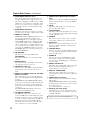
Installing the Batteries
1
To open the battery compartment, press
the small lever and remove the cover.
2
Insert the two supplied batteries (AA/R6)
in accordance with the polarity diagram
inside the battery compartment.
3
Replace the cover and push it shut.
Aiming the Remote Controller
Remote control sensor
AV receiver
Approx. 16 ft. (5 m)
STANDBY indicator

14
Remote Controller—Continued
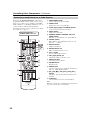
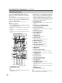
For detailed information, see the pages in parentheses.
ON/STANDBY button (38)
Sets the AV receiver to On or Standby.
REMOTE MODE/INPUT SELECTOR buttons
(51, 93–99)
Selects the remote controller modes and the input
sources.
Arrow [ ]/[ ]/[ ]/[ ] and ENTER buttons
Used to select and adjust settings.
SETUP button
Used to change settings.
LISTENING MODE buttons (62)
Used to select the listening modes.
DIMMER button (52)
Adjusts the display brightness.
DISPLAY button (52)
Displays information about the current input source.
MUTING button (53)
Mutes or unmutes the AV receiver.
VOL [ ]/[ ] button (51)
Adjusts the volume of the AV receiver regardless of
the currently selected remote controller mode.
VIDEO button (83)
Used to change video settings.
RETURN button
Returns to the previous display when changing set-
tings.
AUDIO button (75)
Used to change audio settings.
When the “Audio TV Out” setting is set to “On”
(page 81), this button is disabled.
SLEEP button (53)
Used with the Sleep function.
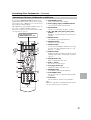
■ Controlling the tuner
To control the AV receiver’s tuner, press the [TUNER]
(or [RECEIVER]) button.
You can select AM or FM by pressing the [TUNER] but-
ton repeatedly.
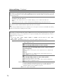
1 Arrow [ ]/[ ] buttons
Used to tune into radio stations.
2 D.TUN button (54)
Selects the Direct tuning mode.
3 DISPLAY button
Displays information about the band, frequency,
preset number, and so on.
4 CH +/– button (55)
Used to select radio presets.
5 Number buttons (54)
Used to select radio stations directly in the Direct
tuning mode. Also you can select a preset directly.
Note:
An Onkyo cassette recorder connected via can also
be controlled in Receiver mode (see page 99).
Controlling the AV Receiver
To control the AV receiver, press the [RECEIVER]
button to select Receiver mode.
You can also use the remote controller to control your
DVD player, CD player, and other components.
See page 91 for more details.
3
4
5
1
2

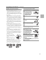
15
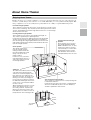
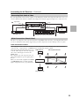
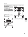
About Home Theater
Thanks to the AV receiver’s superb capabilities, you can enjoy surround sound with a real sense of movement in your
own home—just like being in a movie theater or concert hall. With DVDs you can enjoy DTS and Dolby Digital. With
analog or digital TV, you can enjoy Dolby Pro Logic IIx, DTS Neo:6, or Onkyo’s original DSP listening modes.
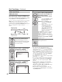
Enjoying Home Theater
Front left and right speakers
These output the overall sound. Their role in a home theater is to provide a solid
anchor for the sound image. They should be positioned facing the listener at about
ear level, and equidistant from the TV. Angle them inward so as to create a triangle,
with the listener at the apex.
Center speaker
This speaker enhances the
front left and right speakers,
making sound movements dis-
tinct and providing a full sound
image. In movies it’s used
mainly for dialog.
Position it close to your TV fac-
ing forward at about ear level, or
at the same height as the front
left and right speakers.
Subwoofer
The subwoofer handles the bass sounds
of the LFE (Low-Frequency Effects)
channel. The volume and quality of the
bass output from your subwoofer will
depend on its position, the shape of your
listening room, and your listening posi-
tion. In general, a good bass sound can
be obtained by installing the subwoofer in
a front corner, or at one-third the width of
the wall, as shown.
Tip: To find the best position for your sub-
woofer, while playing a movie or some
music with good bass, experiment by
placing your subwoofer at various posi-
tions within the room, and choose the one
that provides the most satisfying results.
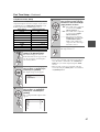
Surround left and right speakers
These speakers are used for precise sound positioning and
to add realistic ambience.
Position them at the sides of the listener, or slightly behind,
about 2–3 feet (60–100 cm) above ear level. Ideally they
should be equidistant from the listener.
Surround back left and right
speakers
These speakers are necessary to
enjoy Dolby Digital EX, DTS-ES
Matrix, DTS-ES Discrete, etc. They
enhance the realism of surround
sound and improve sound localiza-
tion behind the listener. Position
them behind the listener about 2–
3 feet (60–100 cm) above ear level.
Front high left and right speakers
These speakers are necessary to enjoy Dolby PLIIz Height, etc.
They enhance significantly the spatial experience.
Position them at least 3.3 feet (100 cm) above the front left and right
speakers (and as high as possible). Although it is acceptable to
place left and right at an angle slightly wider than the front left and
right speakers. Ideally they should be positioned directly above the
front left and right speakers.
Corner
position
1/3 of wall
position

16
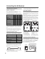
Connecting the AV Receiver
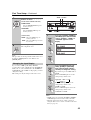
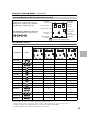
Speaker Configuration
For 7.1-channel surround-sound playback, you need
seven speakers and a powered subwoofer.
The following table indicates the channels you should
use depending on the number of speakers that you have.
* If you’re using only one surround back speaker, connect it to the
SURR BACK L terminals.
No matter how many speakers you use, a powered sub-
woofer is recommended for a really powerful and solid
bass.
To get the best from your surround sound system, you
need to set the speaker settings. You can do this automat-
ically (see page 46) or manually (see page 70).
Attaching the Speaker Labels
The AV receiver’s positive (+) speaker terminals are all
red (the negative (–) speaker terminals are all black).
The supplied speaker cable labels are also color-coded
and you should attach them to the positive (+) side of
each speaker cable in accordance with the above table.
Then all you need to do is to match the color of each
label to the corresponding speaker terminal.
For North American model
• If you are using banana plugs, tighten the speaker ter-
minal before inserting the banana plug.
• Do not insert the speaker code directly into the center
hole of the speaker terminal.
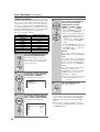
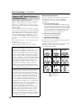
Using Dipole Speakers
You can use dipole speakers for the surround left and
right, surround back left and right and front high left and
right speakers. Dipole speakers output the same sound in
two directions.
Dipole speakers typically have an arrow printed on them
to indicate how they should be positioned. The surround
left and right dipole speakers should be positioned so
that their arrows point toward the TV/screen, while the
surround back left and right and front high left and right
dipole speakers should be positioned so that their arrows
point toward each other, as shown.
Connecting a Powered Subwoofer
Using a suitable cable, connect the AV receiver’s PRE
OUT: SUBWOOFER to an input on your powered sub-
woofer, as shown. If your subwoofer is unpowered and
you’re using an external amplifier, connect the PRE
OUT: SUBWOOFER to an input on the amp.
The same signal is output from each jack.
Connecting Your Speakers
Number of speakers:2345677
Front left ✓✓✓✓✓✓✓
Front right ✓✓✓✓✓✓✓
Center ✓✓✓✓✓
Surround left ✓✓✓✓✓
Surround right ✓✓✓✓✓
Surround back* ✓
Surround back left ✓
Surround back right ✓
Front high left ✓
Front high right ✓
Speaker Color
Front left, Zone 2 left White
Front right, Zone 2 right Red
Center Green
Surround left Blue
Surround right Gray
Surround back left Brown
Surround back right Tan
Front high left White
Front high right Red
2
3
4
5
6
7 8
2
1
3
4
5
7 8
9 10
6
1
9 10
TV/screen TV/screen
1. Subwoofer
2. Front left speaker
3. Center speaker
4. Front right speaker
5. Surround left speaker
6. Surround right speaker
7. Surround back left
speaker
8. Surround back right
speaker
9. Front high left speaker
10.Front high right speaker
Dipole speakers
Normal speakers
LINE INPUT
LINE INPUT
Powered
subwoofer

17
Connecting the AV Receiver—Continued
Speaker Connection Precautions
Read the following before connecting your speakers:
• North American/Taiwan models: You can connect
speakers with an impedance of between 6 and 16
ohms. If you use speakers with a lower impedance,
and use the amplifier at high volume levels for a long
period of time, the built-in amp protection circuit may
be activated.
• Other models: You can connect speakers with an
impedance of between 4 and 16 ohms. If the imped-
ance of any of the connected speakers is 4 ohms or
more, but less than 6 ohms, be sure to set the minimum
speaker impedance to “4ohms” (see page 43). If you
use speakers with a lower impedance, and use the
amplifier at high volume levels for a long period of
time, the built-in protection circuit may be activated.
• Disconnect the power cord from the wall outlet before
making any connections.
• Read the instructions supplied with your speakers.
• Pay close attention to speaker wiring polarity. In other
words, connect positive (+) terminals only to positive
(+) terminals, and negative (–) terminals only to nega-
tive (–) terminals. If you get them the wrong way
around, the sound will be out of phase and will sound
unnatural.
• Unnecessarily long, or very thin speaker cables may
affect the sound quality and should be avoided.
• If you use 4 or 5 speakers, connect each of the two
surround speakers to the SURR L/R terminals. Do not
connect them to the SURR BACK L/R or FRONT
HIGH L/R terminals.
• Be careful not to short the
positive and negative wires.
Doing so may damage the AV
receiver.
• Make sure the metal core of
the wire does not have contact
with the AV receiver’s rear
panel. Doing so may damage the AV receiver.
• Don’t connect more than one cable to each speaker
terminal. Doing so may damage the AV receiver.
• Don’t connect one speaker to several terminals.
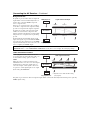
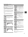
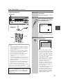
Connecting the Speaker Cables
FRONT HIGH L/R, ZONE 2 L/R
(North American/Taiwan models)
1
Strip 1/2"-5/8" (12-
15 mm) of insulation
from the ends of the
speaker cables, and
twist the bare wires
tightly, as shown.
2
Unscrew the terminal.
3
Fully insert the bare
wires.
4
Screw the terminal tight.
1
Strip 3/8"-1/2" (10-
12 mm) of insulation
from the ends of the
speaker cables, and
twist the bare wires
tightly, as shown.
2
While pressing the lever,
insert the wire into the
hole, and then release the
lever.
Make sure that the
terminals are gripping the bare wires, not
the insulation.
1/2"-5/8"(12-15 mm)
3/8"-1/2"(10-12 mm)

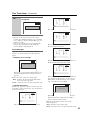
18
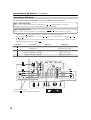
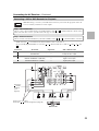
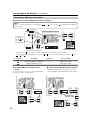
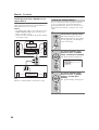
Connecting the AV Receiver—Continued
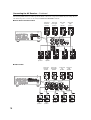
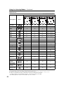
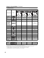
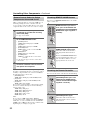
The following illustration shows which speaker should be connected to each pair of terminals. If you’re using only one
surround back speaker, connect it to the left (L) SURR BACK SPEAKERS terminals.
■ North American/Taiwan models
■ Other models
Surround
back left
speaker
Surround
back right
speaker
Surround
left
speaker
Surround
right
speaker
Front high
left
speaker
Front high
right
speaker
Front left
speaker
Front right
speaker
Center
speaker
Front high
left
speaker
Front high
right
speaker
Front left
speaker
Front right
speaker
Center
speaker
Surround
back left
speaker
Surround
back right
speaker
Surround
left
speaker
Surround
right
speaker

19
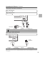
Connecting the AV Receiver—Continued
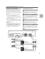
The FRONT L/R and SURR BACK L/R terminal posts
can be used with front speakers and surround back
speakers respectively, or bi-amped to provide separate
tweeter and woofer feeds for a pair of front speakers that
support bi-amping, providing improved bass and treble
performance.
• When bi-amping is used, the AV receiver is able to
drive up to 5.1 speakers in the main room.
• For bi-amping, the FRONT L/R terminal posts con-
nect to the front speakers’ woofer terminals. And the
SURR BACK L/R terminal posts connect to the front
speakers’ tweeter terminals.
• Once you’ve completed the bi-amping connections
shown below and turned on the AV receiver, you must
set the “Speaker Type” setting to “Bi-Amp” to enable
biamping (see page 43).
Important:
• When making the bi-amping connections, be sure
to remove the jumper bars that link the speakers’
tweeter (high) and woofer (low) terminals.
• Bi-amping can only be used with speakers that support
bi-amping. Refer to your speaker manual.
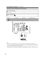
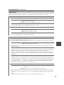
Bi-amping Speaker Hookup
Bi-amping the Front Speakers
1
Connect the AV receiver’s FRONT R positive (+)
terminal to the right speaker’s positive (+) Woofer
(low) terminal. And connect the AV receiver’s
FRONT R negative (–) terminal to the right
speaker’s negative (–) Woofer (low) terminal.
2
Connect the AV receiver’s SURR BACK R posi-
tive (+) terminal to the right speaker’s positive (+)
Tweeter (high) terminal. And connect the AV
receiver’s SURR BACK R negative (–) terminal
to the right speaker’s negative (–) Tweeter (high)
terminal.
3
Connect the AV receiver’s FRONT L positive (+)
terminal to the left speaker’s positive (+) Woofer
(low) terminal. And connect the AV receiver’s
FRONT L negative (–) terminal to the left
speaker’s negative (–) Woofer (low) terminal.
4
Connect the AV receiver’s SURR BACK L posi-
tive (+) terminal to the left speaker’s positive (+)
Tweeter (high) terminal. And connect the AV
receiver’s SURR BACK L negative (–) terminal to
the left speaker’s negative (–) Tweeter (high) ter-
minal.
L
R
FRONT SPEAKERS
L
R
Woofer (low)
Tweeter (high)
Tweeter (high)
Woofer (low)
Left speaker
Right speaker

20
Connecting the AV Receiver—Continued
This section explains how to connect the supplied indoor
FM antenna and AM loop antenna, and how to connect
commercially available outdoor FM and AM antennas.
The AV Receiver won’t pick up any radio signals with-
out any antenna connected, so you must connect the
antenna to use the tuner.
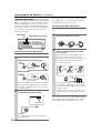
Connecting the Indoor FM Antenna
The supplied indoor FM antenna is for indoor use only.
If you cannot achieve good reception with the supplied
indoor FM antenna, try a commercially available out-
door FM antenna instead (see page 21).
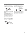
Connecting the AM Loop Antenna
The supplied indoor AM loop antenna is for indoor use
only.
If you cannot achieve good reception with the supplied
indoor AM loop antenna, try using it with a commer-
cially available outdoor AM antenna (see page 21).
Connecting Antenna
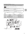
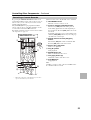
1
Attach the FM antenna, as shown.
■ North American/Taiwan models
■ Other models
Once your AV Receiver is ready for use, you’ll
need to tune into an FM radio station and adjust
the position of the FM antenna to achieve the best
possible reception.
2
Use thumbtacks or something similar to
fix the FM antenna into position.
Caution:
Be careful that you don’t injure yourself when
using thumbtacks.
FM ANTENNA
jack
AM ANTENNA push terminals
Insert the plug fully
into the jack.
Insert the plug fully
into the jack.
Thumbtacks, etc.
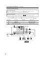
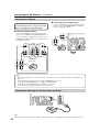
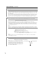
1
Assemble the AM loop antenna, inserting
the tabs into the base, as shown.
2
Connect both wires of the AM loop
antenna to the AM antenna push termi-
nals, as shown.
(The antenna’s wires are not polarity sensitive, so
they can be connected either way around.)
Make sure that the wires are attached securely and
that the push terminals are gripping the bare
wires, not the insulation.
Once your AV Receiver is ready for use, you’ll
need to tune into an AM radio station and adjust
the position of the AM antenna to achieve the best
possible reception.
Keep the antenna as far away as possible from
your AV Receiver, TV, speaker cables, and power
cords.
Push Insert wire Release
Page is loading ...
Page is loading ...
Page is loading ...
Page is loading ...
Page is loading ...
Page is loading ...
Page is loading ...
Page is loading ...
Page is loading ...
Page is loading ...
Page is loading ...
Page is loading ...
Page is loading ...
Page is loading ...
Page is loading ...
Page is loading ...
Page is loading ...
Page is loading ...
Page is loading ...
Page is loading ...
Page is loading ...
Page is loading ...
Page is loading ...
Page is loading ...
Page is loading ...
Page is loading ...
Page is loading ...
Page is loading ...
Page is loading ...
Page is loading ...
Page is loading ...
Page is loading ...
Page is loading ...
Page is loading ...
Page is loading ...
Page is loading ...
Page is loading ...
Page is loading ...
Page is loading ...
Page is loading ...
Page is loading ...
Page is loading ...
Page is loading ...
Page is loading ...
Page is loading ...
Page is loading ...
Page is loading ...
Page is loading ...
Page is loading ...
Page is loading ...
Page is loading ...
Page is loading ...
Page is loading ...
Page is loading ...
Page is loading ...
Page is loading ...
Page is loading ...
Page is loading ...
Page is loading ...
Page is loading ...
Page is loading ...
Page is loading ...
Page is loading ...
Page is loading ...
Page is loading ...
Page is loading ...
Page is loading ...
Page is loading ...
Page is loading ...
Page is loading ...
Page is loading ...
Page is loading ...
Page is loading ...
Page is loading ...
Page is loading ...
Page is loading ...
Page is loading ...
Page is loading ...
Page is loading ...
Page is loading ...
Page is loading ...
Page is loading ...
Page is loading ...
Page is loading ...
Page is loading ...
Page is loading ...
Page is loading ...
Page is loading ...
-
 1
1
-
 2
2
-
 3
3
-
 4
4
-
 5
5
-
 6
6
-
 7
7
-
 8
8
-
 9
9
-
 10
10
-
 11
11
-
 12
12
-
 13
13
-
 14
14
-
 15
15
-
 16
16
-
 17
17
-
 18
18
-
 19
19
-
 20
20
-
 21
21
-
 22
22
-
 23
23
-
 24
24
-
 25
25
-
 26
26
-
 27
27
-
 28
28
-
 29
29
-
 30
30
-
 31
31
-
 32
32
-
 33
33
-
 34
34
-
 35
35
-
 36
36
-
 37
37
-
 38
38
-
 39
39
-
 40
40
-
 41
41
-
 42
42
-
 43
43
-
 44
44
-
 45
45
-
 46
46
-
 47
47
-
 48
48
-
 49
49
-
 50
50
-
 51
51
-
 52
52
-
 53
53
-
 54
54
-
 55
55
-
 56
56
-
 57
57
-
 58
58
-
 59
59
-
 60
60
-
 61
61
-
 62
62
-
 63
63
-
 64
64
-
 65
65
-
 66
66
-
 67
67
-
 68
68
-
 69
69
-
 70
70
-
 71
71
-
 72
72
-
 73
73
-
 74
74
-
 75
75
-
 76
76
-
 77
77
-
 78
78
-
 79
79
-
 80
80
-
 81
81
-
 82
82
-
 83
83
-
 84
84
-
 85
85
-
 86
86
-
 87
87
-
 88
88
-
 89
89
-
 90
90
-
 91
91
-
 92
92
-
 93
93
-
 94
94
-
 95
95
-
 96
96
-
 97
97
-
 98
98
-
 99
99
-
 100
100
-
 101
101
-
 102
102
-
 103
103
-
 104
104
-
 105
105
-
 106
106
-
 107
107
-
 108
108


Ask a question and I''ll find the answer in the document
Finding information in a document is now easier with AI