Page is loading ...

58D6002 1/11 Rev. 8
ON
OFF
586002
csvf vfcs cover
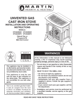
This is an unvented gas-red heater. It uses air
(oxygen) from the room in which it is installed.
Provisions for adequate combustion and
ventilation air must be provided. Refer to page
7.

2
58D6002
Unvented Cast Iron Gas Stoves
Gas Pressures ....................................................... 5
Gas Specications ................................................. 5
Ignition Controls ..................................................... 5
Pilot ........................................................................ 5
Thermal Generator ................................................. 5
Connect Optional Wall Switch ............................. 13
Checking System Operation ................................ 13
CSVF20 / VFCS20 ............................................... 14
Rock Wool Placement .......................................... 14
CSVF30 / VFCS30 ............................................... 15
Pilot Flame.................................................................. 16
Burner Flame ....................................................... 16
For Your Safety Read Before Lighting ................. 18
Millivolt Control Lighting Instructions .................... 19
To Turn Off Gas to Heater .................................... 19
Match Lighting Instructions .................................. 20
CSVF20/VFCS20 Logs and Burner Assembly ..... 23
CSVF30/VFCS30 Burner Assembly ..................... 25
CSVF30/VFCS30 Logs ........................................ 27

58D6002
3
Unvented Cast Iron Gas Stoves
13. Avoid any drafts that alter burner ame patterns. Do not
allow fans to blow directly into replace. Do not place
a blower inside burn area of rebox. Ceiling fans may
create drafts that alter burner ame patterns. Sooting
and improper burning will occur.
14. Candles, incense, oil lamps, etc. produce
combustion by-products including soot. Vent-free
appliances will not lter or clean soot produced by
these types of products. In addition, the smoke and/or
aromatics (scents) may be reburnt in the vent-free
appliance which can produce odors. It is recommended
to minimize the use of candles, incense, etc. while the
vent-free appliance is in operation.
15. This is an unvented gas-fired heater. It uses air
(oxygen) from the room in which it is installed. Provi-
sions for adequate combustion and ventilation air must
be provided. Refer to Page 7.
16. This heater shall not be installed in a room or space
unless the required volume of indoor combustion air is
provided by the method described in the National Fuel
Gas Code, ANSI Z223.1/NFPA 54, the International
Fuel Gas Code or applicable local codes.
17. Keep room area clear and free from combustible
materials, gasoline and other ammable vapors and
liquids.
18. Unvented gas heaters are a supplemental zone heater.
They are not intended to be a primary heating appli-
ance.
19. Unvented gas heaters emit moisture into the living
area. In most homes of average construction, this
does not pose a problem. In houses of extremely
tight construction, addition mechanical ventilation
is recommended.
20. During manufacturing, fabricating and shipping,
various components of this appliance are treated
with certain oils, lms or bonding agents. These
chemicals are not harmful but may produce
annoying smoke and smells as they are burned
off during the initial operation of the appliance;
possibly causing headaches or eye or lung irrita-
Continued on page 4
1. Due to high temperatures, the appliance should be
located out of trafc and away from furniture and
draperies.
2. Children and adults should be alerted to the hazard
of high surface temperature and should stay away
to avoid burns or clothing ignition.
3. Young children should be carefully supervised when
they are in the same room with the appliance.
4. Do not place clothing or other ammable material
on or near the appliance.
5. Any safety screen or guard removed for servicing an
appliance, must be replaced prior to operating the
heater.
6. Installation and repair should be done by a qualied
service person.
7. To prevent malfunction and/or sooting, an unvented
gas heater should be cleaned before use and at least
annually by a professional service person. More
frequent cleaning may be required due to exces-
sive lint from carpeting, bedding material, etc. It is
imperative that control compartments, burners and
circulating air passageways be kept clean.
Please leave these instructions with the appliance.
Please retain these instructions for future reference.
8. Early signs of
carbon monoxide poisoning are similar to the u with
headaches, dizziness and/or nausea. If you have these
signs, obtain fresh air immediately. Have the heater
serviced as it may not be operating properly.
9. The installation must conform with local codes or, in
the absence of local codes, with the
10. This unit complies with the latest edition of ANSI
Z21.11.2, Unvented Heaters.
11. Do not install heater in a bathroom or bedroom unless
approved for bedroom use.
12. Correct installation of the ceramic ber logs, proper
location of the heater, and annual cleaning are neces-
sary to avoid potential problems with sooting. Sooting,
resulting from improper installation or operation, can
settle on surfaces outside the replace. See log place-
ment instructions for proper installation.

4
58D6002
Unvented Cast Iron Gas Stoves
Continued from page 3
tion. This is a normal and temporary occurrence.
The initial break-in operation should last two to three
hours with the burner at the highest setting. Provide
maximum ventilation by opening windows or doors to
allow odors to dissipate. Any odors remaining after this
initial break-in period will be slight and will disappear
with continued use.
21. Input ratings are shown in BTU per hour and are for
elevations up to 2,000 feet. For elevations above 2,000
feet, input ratings should be reduced 4 percent for each
1,000 feet above sea level. Refer to the National Fuel
Gas Code.
22. The appliance and its appliance main gas valve must
be disconnected from the gas supply piping system
during any pressure testing of that system at test pres-
sures in excess of 1/2 psig (3.5 kPa).
23. The appliance must be isolated from the gas supply
piping system by closing its equipment shutoff valve
during any pressure testing of the gas supply piping
system at test pressures equal to or less than 1/2 psig
(3.5 kPa).
24. Do not use this room heater if any part has been under
water. Immediately call a qualied service technician
to inspect the room heater and to replace any part of
the control system and any gas control which has been
under water.
25. Never burn solid fuels in an unvented room heater,
replace or stove.
26. Do not set kettles or humidifying devices on top of
stove.
27. The stove door/screen must be closed when the appli-
ance is operating. The screen shall have openings for
induction of combustion air.
Adhere to all local codes or, in their absence, the latest edition of THE NATIONAL FUEL
GAS CODE ANSI Z223.1 or NFPA54 which can be obtained from…
1430 Broadway
New York, NY 10018
or
Batterymarch Park
Quincy, MA 02269
Fuels used in gas, woodburn-
ing or oil red appliances, and the products of combus-
tion of such fuels, contain chemicals known to the State
of California to cause cancer, birth defects and other
reproductive harm.
California Health & Safety Code Sec. 25249.6
WARNING
!
HOT GLASS WILL
CAUSE BURNS.
DO NOT TOUCH GLASS
UNTIL COOLED.
NEVER ALLOW CHILDREN
TO TOUCH GLASS.
Nous recommandons que nos
appareils de chauffage au gaz
soient installés et entretenus par
des professionnels qui ont été
accrédités aux È.U. par le National
Fireplace Institute ® (NFI) comme
étant des spécialistes du NFI en
matièred’appareils de chauffage
au gaz.

58D6002
5
Unvented Cast Iron Gas Stoves
ON
OFF
ST1164
CSVF controls
Off/Pilot/On Knob
Hi/Lo Knob
Door
Figure 1 -
Cast Iron Stove (Single Door)
Optional Remote
Receiver
Fan Switch
Piezo
Handle
On/Off
Switch
ST1164
ON
OFF
ST1165
VFCS controls
Figure 2 -
Cast Iron Stove (Double Door)
Break-Away
Handle
Store Break-
Away Handle
Here
Optional Fan Switch
Off/Pilot/On Knob
Hi/Lo Knob
Piezo
Optional
Remote
Receiver
On/Off
Switch
Natural Propane (LP)
Regulator Pressure 3.5” w.c. 10.0” w.c.
Pilot Regulator 3.5” w.c. n/a
Max. Gas Inlet Pressure 10.5” w.c. 13.0” w.c.
Min. Gas Inlet Pressure 5.0" w.c. 11.0" w.c.
Max.Input Min. Input
Model Fuel Control BTU/h BTU/h
CSVF20SNV Nat. Millivolt 10,000 6,000
CSVF20SPV LP Millivolt 10,000 6,000
CSVF30SNV Nat. Millivolt 32,000 20,000
CSVF30SPV LP Millivolt 32,000 20,000
VFCS20DNV Nat. Millivolt 10,000 6,000
VFCS20DPV LP Millivolt 10,000 6,000
VFCS30DNV Nat. Millivolt 32,000 20,000
VFCS30DPV LP Millivolt 32,000 20,000
Piezo ignitor allows ignition of the pilot without the use of
matches.
- All gas to the burner is shut off at
the valve.
- Valve position to light/maintain a
standing pilot.
- Valve position to turn burners ON/
OFF with remote switch.
- Variable position to control ame
height (heat output). Both front and
rear burners are in operation to pro-
vide realistic glow and yellow ame.
The gas log heater is tted with a specially designed safety
pilot (ODS assembly) light which senses the amount of
oxygen available in the room and shuts the gas log heater
off if the oxygen level begins to drop below a satisfactory
level. The pilot can only be relit when adequate fresh air
is available.
The millivolt gas log pilot is tted with a millivolt thermopile
generator to provide power for remote activation.
An external regulator is required to reduce supply
pressure to a maximum of 10.5" w.c. on Natural Gas sys-
tems operating at higher pressure.
An external regulator is required to reduce supply
pressure to a maximum of 13.0" w.c. for LP systems.

6
58D6002
Unvented Cast Iron Gas Stoves
A
C
B
586002
CSVF dims
A 21Z\v" 26C\v"
B 23" 28Z\x"
C 16Z\x" 19C\v"
Figure 3 -
Stove Dimensions

58D6002
7
Unvented Cast Iron Gas Stoves
Check your packing list to verify that all listed parts have
been received. You should have the following:
• Cast Iron Stove with Burner Assembly
• Installation/Operating Instructions
• Ceramic Fiber Logs
• Touch-up Paint
Millivolt controlled heater designed to be operated with
optional devices for ON/OFF functions.
• Hand-Held Remote with Manual Receiver
• Wall Switch with 15' Wire
Carefully inspect the contents for shipping damage. If any
parts are missing or damaged, immediately inform the
dealer from whom you purchased the appliance.
You must have the following items available before pro-
ceeding with installation:
• External regulator (for Propane/LPG) or high pressure
natural gas (1 to 2 psi system)
• Piping which complies with local codes
• Sediment trap (recommended)
• Pipe wrench
• Pipe sealant approved for use with propane/LPG (resis-
tant to sulfur compounds)
• Manual shutoff valve
• Tee joint
• Screwdrivers
G Graphite
EBL Enamel Black
ES Enamel Sand
EMB Enamel Brown
National
Fuel Gas Code, ANSI Z223.1/NFPA 54
International Fuel Gas Code

8
58D6002
Unvented Cast Iron Gas Stoves
Figure 4
D
Minimum
to Either
Side Wall
E
Minimum
A
ST1167
side ceiling clearances
F
Minimum
36"
in Front
C
B
ST1168
front rear clearances
G
G
ST1169
corner clearances
D
Minimum
to Either
Side Wall
F Minimum
ST1170
back side wall clearances
Ceiling
Ceiling
Mantel
Side
Wall
ST1167
ST1168
ST1169
ST1170
Figure 4 -
Minimum Clearances
CSVF20 / VFSC20 72" 12" 16" 1" 1" 1/2" 1Z\x"
CSVF30 / VFSC30 72" 12" 18" 2" 2" 1" 1/2"

58D6002
9
Unvented Cast Iron Gas Stoves
ON
OFF
A
C
B
ST1171
alcove clearances
Figure 5 -
Alcove Installation
ST1171
Maintain minimum side and back clearances
when placing stove in alcove.
CSVF20/VFCS20 38Z\x" 23" 36"
CSVF30/VFCS30 52" 34" 36"

10
58D6002
Unvented Cast Iron Gas Stoves
1. Remove two (2) straps. Figure 6
2. Open plastic bag and slide to bottom of unit. Figure 7
3. Lift up on ash lip and pivot down to open control door.
Figure 8
4. Lift up on front. Pivot bottom of front out. Remove front.
Figure 8
5. Lift screen to remove.
6. Remove log box from inside of unit.
7. Lift unit off pallet. Lift unit up high enough to clear upright
supports unit is sitting on.
You will need at least two (2) strong people to lift
unit off of pallet.
ON
OFF
LOGS
ST1172
stove on pallet
Plastic
Bags
Straps
Pallet
ST1172
Figure 6 -
Remove Straps and Plastic from Unit
PILOT
OFF
REMOTE CONTROL
LOGS
ST1173
remove hearth door
Hearth
Door
Ash Lip
Control Door
ST1173
Figure 7 -
Remove Hearth Door - Open Control Door
PILOT
OFF
REMOTE CO
NTROL
LOGS
ST1174
remove log box
Log Box
ST1174
Figure 8 -
Remove Log Box

58D6002
11
Unvented Cast Iron Gas Stoves
FP2447
gas connection
3” Min.
Pipe Coupling
To Heater
Valve
Gas
Supply
Inlet
Hold heater valve rmly with a wrench to prevent movement when connect-
ing to inlet pipe.
Manual Shutoff Valve
Pipe
Stainless
Flexible
Tube
Figure 9 -
Gas Connection
to reduce the supply tank pressure to a maximum of 13" w.
c. This is in addition to the internal regulator in the heater valve.
Locations that the
Pressure Tapping
Point May Be
Installed
A qualied gas appliance installer must connect the heater to the gas supply.
Consult all local codes.
Figure 9
Figure 9
FP2447

12
58D6002
Unvented Cast Iron Gas Stoves
The heater gas inlet connection is 3/8" NPT at the valve.
The inlet is located on left side of stove. Remove front
control plate to better access the inlet.
When tightening up the joint to the valve, hold the valve
securely with a wrench to prevent movement.
Test all gas joints from the gas meter to the heater valve
for leaks using a gas analyzer or soap and water solution
after completing connection.
Check the gas pressure with the appliance burning and
the control set to
Figure 10
The valve regulator controls the burner pressure which
should be checked at the pressure test point.
If outlet pressure is low, check inlet pressure against data
plates or manual.
Turn captured slotted screw counter clockwise 2 or 3
turns and then place tubing to pressure gauge over test
point (Use test point “OUT” closest to control knob). After
taking pressure reading, be sure and turn captured screw
clockwise rmly to re-seal. Do not over torque. Check for
gas leaks.
Remove control panel to access gas valve.
FP2781
millivolt valve
Test Port "OUT"
FP2781
Figure 10 -
Pressure Test Point Location Millivolt Control
1. Remove cover on control panel to show opening
for remote receiver. Figure 11
2. Follow remote receiver Instructions to make all
necessary wiring connections.
3. Place remote receiver in the opening of control
panel. Use two screws provided to attach remote
receiver to the control panel. Figure 11
Do not place remote in combustion chamber.
O
N
O
F
F
ST1175
remote receiver
Remote
Receiver
Cover
ST1175
Figure 11 -
Install Remote Receiver

58D6002
13
Unvented Cast Iron Gas Stoves
The millivolt valve is a self-powered combination gas control
1. Use 18 awg, two-wire cable, 15 feet maximum length.
2. At one end of the cable, connect both wires to the wall switch. At the other end, connect
one wire to TP/TH and one wire to TH, or connect the wall switch to the two male (0.25")
terminals on the left side of the unit. The color of the wires does not matter.
ST1176
Millivolt valve wiring
On/Off
Switch
Wall
Switch
Optional Wall
Switch or
Remote
ODS Pilot
Millivolt Valve
Figure 12 -
Wiring Diagram
Switch
Spade Terminal
On/Off
Switch
ODS Pilot
3
1
2
The millivolt system and individual components may be checked with a millivolt meter having
a 0-1000 mV range. Conduct each check shown in chart below by connection meter test leads
to terminals as indicated.
a. If the reading is more than 100 millivolts and the automatic valve still does not come on,
replace the control.
b. If the closed circuit reading (“A” reading) is less than 100 millivolts, determine cause for
low reading, proceed to Section B below.
1. Check gas pressure to the unit. If
gas pressure is within minimum
and maximum on data plate, then
check pilot voltage, 325 millivolts
minimum. If the minimum millivolt
reading is not obtainable, replace
pilot.
A Complete 2 & 3 Closed Closed
System
B Thermopile 1 & 2 Open Open

14
58D6002
Unvented Cast Iron Gas Stoves
Figure 13
1. Install back log (#1) on back of burner assembly.
2. Install front log (#2) on 2 pegs on burner assembly.
1. Break rock wool into dime-sized pieces.
2. Place rock evenly across rock wool tray and front burner
as shown in Figure 14.
• Rock wool depth must not be more than 1".
• Do not place rock wool past the bend in rock
wool tray.
• Do not place rock wool on rear burner.
Figure 13 -
Install Logs on Grate - CSVF20/VFCS20
LG938
CSVF20 log place
Back Log #1
Front Log #2
LG938
PILOT
OFF
REMOTE CONTROL
LG939
CSVF rock wool
Figure 14 -
Rock Wool Installation
Rock Wood Tray
Rock
Wool
Bend in Rock
Wool Tray
LG939

58D6002
15
Unvented Cast Iron Gas Stoves
— This unit is supplied with four
ceramic ber logs. Do not handle these logs with your bare
hands.
After handling the logs, wash your
hands gently with soap and water to remove any traces
of bers.
Figure 15
1. Install back log (#1) on rear log support bracket.
2. Install left bottom log (#2) on left log support bracket in
front of back log.
3. Install right bottom log (#3) on right log support bracket
in front of back log.
4. Install top left log (#4) on top of left bottom log.
5. Install top right log (#5) on top of right bottom log.
PILOT
OFF
REMOTE CO
NTROL
LG937
CSVF30 log place
Left Bottom
Log #2
Back Log #1
Top Left
Log #4
Figure 15 -
Place Logs on Grate - CSVF30/VFSC30
Right
Bottom
Log #3
Right Top
Log #5
Rear Log
Support
Bracket
Left Log
Support
Bracket
Right Log
Support Bracket
LG937

16
58D6002
Unvented Cast Iron Gas Stoves
FP2273
pilot bad flame
FP2272
pilot correct flame
In addition, periodically check the ames visually during operation.
It should just touch
the top of the thermocouple tip for natural. Refer to Figure 16 for correct pilot ame.
If the pilot ame does not touch the thermocouple, then the burners cannot function reliably.
Refer to Figure 17 for incorrect shape of pilot ame.
Figure 16 -
Correct Pilot Flame Appearance
Figure 17 -
Incorrect Pilot Flame Appearance
Thermocouple
for Natural
Thermocouple
for LP
Thermocouple
for LP
Thermocouple
for Natural
FP2272
FP2273
The left and right rear ames should be yellow and extend
1"-2" above middle logs. The yellow ames should not
contact the logs. There should be glowing embers
on the front surface of the middle log.
PILOT
OFF
REMOTE CONTROL
LG940
CSVF VFSC log flames
Figure 18 -
Correct Burner Flame Appearance
LG940

58D6002
17
Unvented Cast Iron Gas Stoves
Do not allow fans to blow directly into the stove.
Do not place a blower inside the burn area of the stove. Ceiling fans may create drafts that alter
ame patterns. Sooting and improper burning will result.
During manufacturing, fabricating and shipping, various components of this appliance are treated
with certain oils, lms or bonding agents. These chemicals are not harmful, but may produce annoy-
ing smoke and smells as they are burned off during the initial operation of the appliance, possibly
causing headaches or eye or lung irritation. This is a normal and temporary occurrence.
The initial break-in operation should last two to three hours with the burner at the highest setting.
Provide maximum ventilation by opening windows or doors to allow odors to dissipate. Any odors
remaining after this initial break-in will be slight and will disappear with continued use.

18
58D6002
Unvented Cast Iron Gas Stoves
This appliance is equipped with an ignition device which automatically lights the pilot. If the
piezo is not working properly, refer to Match Lighting instructions on Page 20.
BEFORE OPERATING smell all around the appliance area for gas. Be sure to smell next
to the oor because some gas is heavier than air and will settle on the oor.
• Turn off all gas to the appliance.
• Open windows.
• Do not attempt to light any appliance.
• Do not touch any electric switch; do not use any phone in your building.
• Immediately call your gas supplier from a neighbor's phone. Follow the gas supplier's
instructions.
• If you cannot reach your gas supplier, call the re department.
Use only your hand to push in, or turn the gas control knob. Never use tools. If the knob will
not push in or turn by hand, don't try to repair it. Call a qualied service technician. Force
or attempted repair may result in a re or explosion.
Do not use this appliance if any part of it has been under water. Immediately call a qualied
service technician to inspect the appliance and to replace any part of the control system
and any gas control that has been under water.
PILOT
OFF
REMOTE CONTROL
ST1177
burner controls
Pilot
Optional Re-
mote Receiver
Hi/Lo Knob
Off/Pilot/On Knb
Optional Fan
ST1177
Burner Controls - Piezo
Ignitor, Control Knobs and
Optional Controls
Piezo

58D6002
19
Unvented Cast Iron Gas Stoves
1. Read the safety information label.
2. Make sure the manual shutoff valve is fully open.
3. This gas log set is equipped with an ignition device (piezo) which automatically lights the pilot.
If piezo ignitor does not light the pilot, refer to instructions for “Match Lighting Instructions,”
Page 20.
4. Turn gas control knob clockwise to the OFF position, and turn ON/OFF switch to OFF posi-
tion.
5. Wait (5) minutes to clear out any gas. Then smell for gas, including near the oor. If you smell
gas, STOP! Follow “What to Do if You Smell Gas,” page 18. If you don't smell gas, go to next
step.
6. From OFF position, turn the gas control knob counterclockwise to IGN position. Push in
control knob for 5 seconds. NOTE: If you are running the heater for the rst time, it will
be necessary to press in the control knob for 30 seconds to allow air to bleed out of the
gas piping.
7. With the control knob pushed in, push in and release the piezo ignitor button to light the
pilot.
8. Continue pushing the control knob in for a further 10 seconds to prevent the ame detector
from shutting off the gas while the probe is warming up. Release the control knob.
9. Turn gas control knob counterclockwise to the ON position.
10. After the pilot has been lit for one minute, the burners can be turned on. Turn the ON/OFF
switch to ON position.
11. If the gas logs will not operate, follow the instructions “To Turn Off Gas To Heater” below and
call your service technician or gas supplier.
1. Turn ON/OFF switch to OFF position.
2. Turn control knob clockwise to OFF position to completely shut off the heater.
3. If applicable: Turn off all electric power to the heater.
Pilot
FP2275
ST1178
control cover plate
OFF
ON
ST1179
on off switch
Control Cover Plate for Millivolt
Hi/Lo Control
Ignitor/Pilot
Control
On/Off Switch
(Located on Side of
Stove)
ST1178

20
58D6002
Unvented Cast Iron Gas Stoves
1. Open stove door. Remove any items necessary for easy access to the pilot (for example: logs,
screens, etc.).
2. Follow appropriate lighting instructions found previously. Instead of pushing and releasing the piezo
button, light a match and hold the ame to the end of the pilot and ignite the pilot.
3. After control knob has been released and pilot stays lit, reinstall any items that were removed for pilot
access.
4. Call a qualied service technician for repair or replacement of the piezo ignitor.
Remove logs, handling carefully by holding gently at each end. Gloves are recommended to
prevent skin irritation from ceramic bers. If skin becomes irritated, wash gently with soap and
water. Refer to manual for correct log placement.
• Do not use cleaning uid to clean logs or any part of heater.
• Brush logs with soft bristle brush or vacuum with brush attachment.
• Vacuum loose particles and dust from the front and rear burners, control and piezo covers
and grate weldment.
• Inspect and clean burner air intake holes. Remove lint or particles with vacuum, brush,
or pipe cleaners. Failure to keep air intake holes clean will result in sooting and poor
combustion.
• External case should be dusted and wiped with a moist cloth.
• Inspect and clean burner air intake holes. Remove lint or particles with vacuum, brush or
pipe cleaners. Failure to keep air intake holes clean will result in sooting and poor com-
bustion.
• Inspect and clean all burner ports.
• Inspect ODS pilot for operation and accumulation of lint at air intake holes.
• Verify ame pattern and log placement for proper operation.
• Verify smooth and responsive ignition of main burner and rear burner.
/