Garmin GSD 24 Installation Instructions Manual

Category
Networking
Type
Installation Instructions Manual

This manual is also suitable for

GSD
24/26 Installation Instructions
To obtain the best performance and to avoid damage to your boat, install the
Garmin
®
GSD 24/26 unit according to the following instructions. Professional
installation of the unit is highly recommended, because specic knowledge of
boat construction is required to properly install the unit.
If
you experience difculty during the installation, contact Garmin Product Support.

Help us better support you by completing our online registration today.
Go to http://my.garmin.com.
Keep the original sales receipt, or a photocopy, in a safe place.

Contact Garmin Product Support if you have any questions about this product.
In the USA, go to www.garmin.com/support, or contact Garmin USA by
phone at (913) 397.8200 or (800) 800.1020.
In the UK, contact Garmin (Europe) Ltd. by phone at 0808 2380000.
In Europe, go to www.garmin.com/support and click  for
in-country support.


You are responsible for the safe and prudent operation of your vessel. Sonar is
a tool that will enhance your awareness of the water beneath your boat. It does
not relieve you from the responsibility of observing the water around your boat
as you navigate.
When drilling or cutting, always check the opposite side of the surface. Be aware
of fuel tanks, electrical cables, and hydraulic hoses.

Failure to install and maintain this equipment in accordance with these
instructions could result in damage or injury.
Always wear safety goggles, ear protection, and a dust mask when drilling,
cutting, or sanding.

This equipment must be installed by a qualied marine installer.

A transducer is required to send and receive the sonar signal from the
GSD 24/26. Proper transducer selection and installation are critical to the
operation of the GSD 24/26. Because mounting locations vary, see your local
Garmin dealer or contact Garmin Product Support for more information. Go to
www.garmin.com to view a full list of transducers.


The GSD 24/26 must be installed according to the following instructions to get
the best possible performance. If you experience difculty with the installation,
contact Garmin Product Support.
Because every boat is different, you must carefully plan the GSD 24/26 sounder
installation.

Select a mounting location (page 1).

Mount the sounder (page 1).

Connect the sounder to the Garmin Marine Network and to power
(page 2).

Connect the sounder to the transducer (page 2).

 If you are not using the mounting hardware included in the kit, use the
most appropriate tool for securing that hardware.
Drill
#8 (5 mm) drill bit appropriate for mounting surface
1
1
/
4
in. (32 mm) paddle drill bit or hole saw appropriate for mounting surface
#2 Phillips screwdriver
3 mm at screwdriver
Cable ties (optional)
Wire cutter
Wire stripper
1 in. (24 mm) and
19
/
32
in. (15 mm) wrenches
Marine sealant (optional)


The sounder dimensions and mounting hole locations can be reviewed on
the templates included in the sounder package.
The sounder must be mounted in a location where it cannot be submerged.
The sounder must be mounted in a location with adequate ventilation where
it will not be exposed to extreme temperatures.
The sounder should be mounted in such a way that the LED is visible.
The sounder should be mounted so that the power and network cables can
be easily connected.
The sounder should be mounted so that the transducer cable can be
connected. If required, transducer extension cables up to 20 ft. (6 m) are
available through your Garmin dealer.


After you select a mounting location (page 1), determine the mounting
hardware needed for the surface.
Mounting hardware is included with the sounder, but it may not be suitable
for the mounting surface.

If necessary, purchase the mounting hardware.

Complete an action:
Hold the sounder in the intended mounting location and mark the
locations of the mounting holes in the mounting surface, using the
sounder as a template.
Use the template included with your sounder to mark the locations of the
mounting holes.

Drill the mounting holes through the mounting surface.

Secure the sounder to the mounting surface using the selected mounting
hardware.
October 2011 190-00789-02_0C Printed in Taiwan
2 GSD 24/26 Installation Instructions


Do not force a cable into its port. Forcing the cable can damage the pins. If the
cable is properly aligned, the cable should connect easily.
If you are connecting 6-pin transducer to a GSD 24 you must use the included
adaptor. Refer to the GSD 24 Transducer Adaptor Installation Instructions
included in the package for more information.
Before you connect the sounder to the network, power, and the transducer, you
must mount the sounder (page 1).

Route the cables using appropriate tie wraps, fasteners, and sealant to
secure the cables along the route and through any bulkhead or deck
(page 2).

Install the locking rings on the marine network and power cables
(page 2).

Connect the bare-wire end of the power cable to a 12 Vdc power source and
to ground.

Align the notch on the end of the power cable with the power port on the
device, and press the cable into place.

After the cable is seated, turn the locking ring clockwise until it stops.

Select an option:
If you are installing a GSD 24, repeat steps 4 and 5 for the network and
transducer cables.
If you are installing a GSD 26, repeat steps 4 and 5 for the network cable,
and refer to “Connecting the GSD 26 to a Transducer” on page 2.

Select an option:
If your boat is equipped with a GMS 10 network port expander,
connect the network cable to an available port on the GMS 10.
If your boat is not equipped with a GMS 10 network port expander,
connect the network cable directly to the NETWORK port on your
chartplotter.


You must install cord grip plugs in any unused cord grip to ensure that water
cannot enter the transducer wiring block area and damage the sounder.
The terminal blocks are not removable.


Remove the terminal block lid from the sounder with a #2 Phillips
screwdriver.

Select an option:
Feed a sensor cable through the small cord grip
, and pull it into the
terminal block area.
Feed a transducer cable through one of the large cord grips
on the
housing, and pull it into the terminal block area.
Do not tighten the cord grips at this time.

Before you connect the wires, consult the wiring diagrams on pages 3–4 to view
the proper wiring conguration for your transducer and the wiring tables on
page 4 to view specic examples of many Garmin/Airmar transducer wire colors.

Connect the uninsulated section of each wire to the terminal block using a
3 mm at screwdriver.

Connect the bare shield wire to one of the two ground posts under the
terminal block using a #2 Phillips screwdriver.


After all the wire connections are secure, use a 1 in. (24 mm) wrench to
tighten the nut around the transducer cable.
When tightening correctly you will not be able to pull the transducer cable out
of the housing.

Install cord grip plugs in the unused cord grips.

Replace and secure the terminal block lid on the sounder with a #2 Phillips
screwdriver.
The sounder will not operate with the lid removed.

Before you ground the sounder, you must mount it (page 1) and connect the
marine network, power, transducer, and sensors (page 2). The chassis ground
post is located on the exterior of the chassis, adjacent to a corner mounting hole.
Connect the chassis ground post
to the boat water ground circuit.


Cable routing grommets do not create a waterproof seal. To create a waterproof
seal, apply a marine sealant around the grommet and cable after installation. Be
sure to test the system before sealing the grommets.
When routing cables through your boat, it may be necessary to drill holes to
route the connector end of the cables. Rubber grommets are provided to cover
the cable holes for a nished look. You can purchase additional grommets from
your Garmin dealer or directly from Garmin at www.garmin.com.


Mark the location where you want to route the cable.

Using a 1
1
/
4
in. (32 mm) paddle drill bit or hole saw, drill the installation hole.

Route the cable through the hole to the sounder.

Spread the grommet apart at the split, and place it around the cable.

Firmly push the grommet into the installation hole until it is seated.

Apply marine sealant, as needed, to weatherproof the installation hole
(optional).

Before you install locking rings on the cables, you must route the cables.
To help make the cable-routing process easier, the locking rings are packaged
separately from the cables. Each locking ring is packaged in a small bag with a
number on the label for easy identication.

Separate the two halves of the locking ring .
GSD 24/26 Installation Instructions 3

Align the two halves of the locking ring over the cable and snap them
together.

Insert the o-ring into the end of the connector.

You can use these diagrams to identify the connection points for your transducer
wires on the GSD 26 terminal block. Locate your transducer model in the wiring
color tables on page 4 for more information.
In all cases, the outer shield wire connects to one of the two screw posts below
the terminal block with the included ring crimp terminal. If you are connecting two
single-element transducers, connect the second transducer to the duplicate set
of connections on the right side of the terminal block.

LOW FREQ XDUCERLOW FREQ XDUCERLOW FREQ XDCR LOW FREQ XDCR
SHIELD
LOW FREQ XDCR
SHIELD
SHIELD
SHIELD
SHIELD
TEMP
XID
GRND
SHIELD
TEMP
XID
GRND
SPEED
SPD PWR
GRND
SHIELD
TEMP
XID
GRND
SPEED
SPD PWR
GRND
SHIELD
TEMP
XID
GRND
LOW FREQ XDCR
HIGH FREQ XDCR HIGH FREQ XDCR
HIGH FREQ XDCR
HIGH FREQ XDCR
SPEED
SPEED

 The temperature and XID wires can be connected at either location.
LOW FREQ XDUCERLOW FREQ XDUCERLOW FREQ XDCR LOW FREQ XDCR1
SHIELD
LOW FREQ XDCR
SHIELD
SHIELD
SHIELD
SHIELD
TEMP
XID
GRND
SHIELD
TEMP
XID
GRND
SPEED
SPD PWR
GRND
SHIELD
TEMP
XID
GRND
SPEED
SPD PWR
GRND
SHIELD
TEMP
XID
GRND
LOW FREQ XDCR
HIGH FREQ XDCR HIGH FREQ XDCR
HIGH FREQ XDCR
HIGH FREQ XDCR
SPEED
SPEED

 The XID wires can be connected at either location.
LOW FREQ XDUCERLOW FREQ XDUCERLOW FREQ XDCR LOW FREQ XDCR
SHIELD
LOW FREQ XDCR
SHIELD
SHIELD
SHIELD
SHIELD
TEMP
XID
GRND
SHIELD
TEMP
XID
GRND
SPEED
SPEED
SPD PWR
GRND
SHIELD
TEMP
XID
GRND
SPEED
SPEED
SPD PWR
GRND
SHIELD
TEMP
XID
GRND
LOW FREQ XDCR
HIGH FREQ XDCR HIGH FREQ XDCR
HIGH FREQ XDCR
HIGH FREQ XDCR

 The temperature and XID wires can be connected at either location.
LOW FREQ XDUCERLOW FREQ XDUCERLOW FREQ XDCR LOW FREQ XDCR
SHIELD
LOW FREQ XDCR
SHIELD
SHIELD
SHIELD
SHIELD
TEMP
XID
GRND
SHIELD
TEMP
XID
GRND
SPEED
SPD PWR
GRND
SHIELD
TEMP
XID
GRND
SPEED
SPD PWR
GRND
SHIELD
TEMP
XID
GRND
LOW FREQ XDCR
HIGH FREQ XDCR HIGH FREQ XDCR
HIGH FREQ XDCR
HIGH FREQ XDCR
SPEED
SPEED

 The XID wires can be connected at either location.
LOW FREQ XDUCERLOW FREQ XDUCERLOW FREQ XDCR LOW FREQ XDCR
SHIELD
LOW FREQ XDCR
SHIELD
SHIELD
SHIELD
SHIELD
TEMP
XID
GRND
SHIELD
TEMP
XID
GRND
SPEED
SPD PWR
GRND
SHIELD
TEMP
XID
GRND
SPEED
SPD PWR
GRND
SHIELD
TEMP
XID
GRND
LOW FREQ XDCR
HIGH FREQ XDCR HIGH FREQ XDCR
HIGH FREQ XDCR
HIGH FREQ XDCR
SPEED
SPEED
4 GSD 24/26 Installation Instructions

You can use these tables to help identify wire functions on certain Garmin or Airmar
®
transducers.

    

 


010-10272-00 Garmin 50/200 Red Black Bare White Green NA NA NA
010-10182-00 Airmar B117 depth only Blue Black Bare NA NA NA NA NA
010-10182-01 Airmar B117 with temp Blue Black Bare White Brown NA NA NA
010-10183-02 Airmar B744V Blue Black Bare White Brown NA Red Green
010-10192-01 Airmar P66 Blue Black Bare White Brown NA Red Green
010-10193-02 Airmar B744VL Long stem Blue Black Bare White Brown NA Red Green
010-10194-00 Airmar P319 depth only Blue Black Bare NA NA NA NA NA
010-10194-01 Airmar P319 with temp Blue Black Bare White Brown NA NA NA
010-10327-00 Airmar P79 adjustable in-hull Blue Black Bare NA NA NA NA NA
010-10445-00 Airmar M260 for 500W sonar units Blue Black Bare NA NA Orange** NA NA
010-10451-00 Airmar B260 for 500W sonar units Blue Black Bare White Brown NA NA NA
010-10982-00 Airmar B60 with 20º tilt Blue Black Bare White Brown NA NA NA
010-10982-01 Airmar B60 with 12º tilt Blue Black Bare White Brown NA NA NA
010-10983-00 Airmar B45 Narrow Stem Blue Black Bare White Brown NA NA NA
** Brown before 2/1/07

    
010-10640-00 Airmar B260 Blue Black Bare White Orange**
010-10641-00 Airmar M260 Blue Black Bare NA Orange**
010-10642-00 Airmar R99 Blue Black Bare White Orange**
010-10643-00 Airmar R199 Blue Black Bare NA Orange**
010-10703-00 Airmar B258 Blue Black Bare White Orange**
010-11010-00 Airmar B164 with 20º tilt Blue Black Bare White Orange
010-11010-01 Airmar B164 with 12º tilt Blue Black Bare White Orange
010-11140-00 Airmar SS270W widebeam Blue Black Bare White Orange
010-11395-00 Airmar TM260 Blue Black Bare White Orange
**Brown before 2/1/07

   

  

   

 

010-11640-20 Airmar R509LH Blue/White** Bare Black/White Brown Bare White Orange Blue Bare Black Bare
010-11641-20 Airmar R599LH Blue/White** Bare Black/White Brown Bare White Orange Blue Bare Black Bare
010-11642-20 Airmar R109LH Blue/White** Bare Black/White Brown Bare White Orange Blue Bare Black Bare
010-11643-20 Airmar R111LH Blue/White** Bare Black/White Brown Bare White Orange Blue Bare Black Bare
010-11644-20 Airmar M265LH Blue/White** Bare Black/White Brown NA White Orange Blue Bare Black Bare
010-11645-20 Airmar B265LH Blue/White** Bare Black/White Brown NA White Orange Blue Bare Black Bare
010-11646-20 Airmar TM265LH Blue/White** Bare Black/White Brown NA White Orange Blue Bare Black Bare
010-11647-20 Airmar B265LM Blue/White** Bare Black/White Brown NA White Orange Blue Bare Black Bare
010-11650-20 Airmar TM265LM Blue/White** Bare Black/White Brown NA White Orange Blue Bare Black Bare
010-11808-20/21/22 Airmar B175H NA NA NA Brown NA White Orange Blue Bare Black Bare
010-11809-20/21/22 Airmar B175L Blue/White Bare Black/White Brown NA White Orange NA NA NA Bare
010-11810-20/21/22* Airmar B175M Blue Bare Black Brown NA White Orange Blue Bare Black Bare
010-11811-20 Airmar PM265LH Blue/White Bare Black/White Brown NA White Orange Blue Bare Black Bare
010-11812-20 Airmar PM265LM Blue/White Bare Black/White Brown NA White Orange Blue Bare Blue Bare
010-11813-20 Airmar CM599LH Blue/White Bare Black/White Brown Bare White Orange Blue Bare Black Bare
* Can be connected to either Low Freq or High Freq terminal blocks. XID must be connected on the same side.
** Yellow before 11/2010
GSD 24/26 Installation Instructions 5

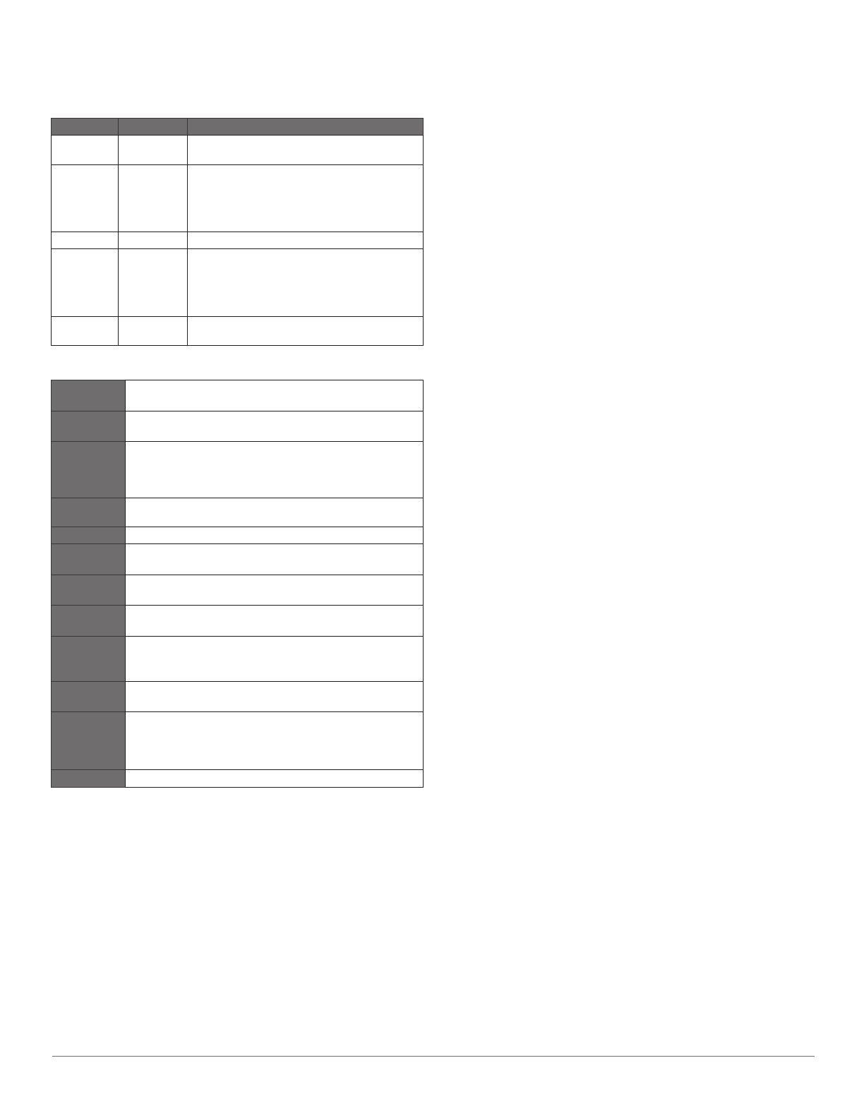
When the sounder is installed, it turns on when the chartplotter is turned on. The
two-color (green and red) LED on the sounder indicates the current operational
status of the device.
  
Green Slow Sounder is connected to a chartplotter and is operating
properly. You should see sonar data on the chartplotter
Red Slow Sounder is turned on, but is not connected to a
chartplotter, is waiting to connect to a chartplotter, or
has a malfunctioning XID. If the sounder is connected to
the chartplotter and this code persists, check the wiring
and connections.
Red/Green Fast Sounder is in test mode.
Red Very Fast System alarm. The chartplotter displays a message
indicating the type of failure. When the alarm condition
is xed, the sounder must be completely disconnected
from and reconnected to its power source to clear the
alarm.
Red Solid Sounder has a hardware failure. Contact Garmin
Product Support for assistance.

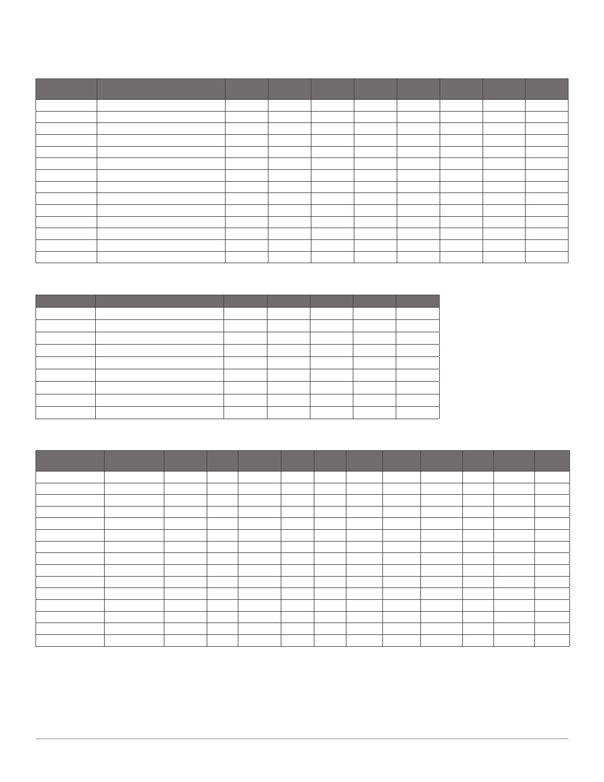
 GSD 24: L × W × H: 8 × 11.2 × 3.2 in. (204 × 283 × 81 mm)
GSD 26: L × W × H: 10.8 × 14.7 × 3.9 in. (274 × 373 × 100 mm)
 GSD 24: 5.27 lb. (2.39 kg)
GSD 26: 11.37 lb. (5.16 kg)
 GSD 24: Fully gasketed, aluminum and steel housing, waterproof to
IEC 529-IPx7.
GSD 26: Fully gasketed, aluminum and steel housing with plastic
access panel, waterproof to IEC 529-IPx7.


From 5°F to 158°F (from -15°C to 70°C)
 10–35 V
 GSD 24: 40 W maximum
GSD 26: 100 W maximum
 GSD 24: 7.5 A
GSD 26: 10 A


GSD 24: 15.75 in. (40 cm)
GSD 26: 23.6 in. (60 cm)
 GSD 24: 25–2,000 W rms*
GSD 26: 25–3,000 W rms*
*dependent upon transducer rating and depth
 GSD 24: 50/200 kHz
GSD 26: 25–210 kHz (dependent upon transducer)
 GSD 24: 5,000 ft. (1,512 m)**
GSD 26: 10,000 ft. (3,048 m)**
**maximum depth, dependent upon transducer, water salinity, bottom
type, and other water conditions
 Garmin Marine Network

Hereby, Garmin International, Inc. declares that this device is in compliance with
the essential requirements and other relevant provisions of Directive 2004/108/
EEC. The Declaration of Conformity may be obtained at
www.garmin.com/compliance.

This device complies with part 15 of the FCC Rules. Operation is subject to the
following two conditions: (1) this device may not cause harmful interference,
and (2) this device must accept any interference received, including interference
that may cause undesired operation. This equipment has been tested and found
to comply with the limits for a Class B digital device, pursuant to part 15 of the
FCC rules. These limits are designed to provide reasonable protection against
harmful interference in a residential installation. This equipment generates, uses,
and can radiate radio frequency energy and may cause harmful interference
to radio communications if not installed and used in accordance with the
instructions. However, there is no guarantee that interference will not occur in a
particular installation. If this equipment does cause harmful interference to radio
or television reception, which can be determined by turning the equipment off
and on, the user is encouraged to try to correct the interference by one of the
following measures:
Reorient or relocate the receiving antenna.
Increase the separation between the equipment and the receiver.
Connect the equipment into an outlet that is on a different circuit from the
GPS unit.
Consult the dealer or an experienced radio/TV technician for help.

Category I radiocommunication devices comply with Industry Canada Standard
RSS-210. Category II radiocommunication devices comply with Industry Canada
Standard RSS-310. This device complies with Industry Canada license-exempt
RSS standard(s). Operation is subject to the following two conditions: (1)
this device may not cause interference, and (2) this device must accept any
interference, including interference that may cause undesired operation of the
device.

This Garmin product is warranted to be free from defects in materials or
workmanship for one year from the date of purchase. Within this period, Garmin
will, at its sole option, repair or replace any components that fail in normal use.
Such repairs or replacement will be made at no charge to the customer for parts
or labor, provided that the customer shall be responsible for any transportation
cost. This warranty does not apply to: (i) cosmetic damage, such as scratches,
nicks and dents; (ii) consumable parts, such as batteries, unless product
damage has occurred due to a defect in materials or workmanship; (iii) damage
caused by accident, abuse, misuse, water, ood, re, or other acts of nature or
external causes; (iv) damage caused by service performed by anyone who is not
an authorized service provider of Garmin; or (v) damage to a product that has
been modied or altered without the written permission of Garmin. In addition,
Garmin reserves the right to refuse warranty claims against products or services
that are obtained and/or used in contravention of the laws of any country.
This product is intended to be used only as a travel aid and must not be used for
any purpose requiring precise measurement of direction, distance, location or
topography. Garmin makes no warranty as to the accuracy or completeness of
map data in this product.
THE WARRANTIES AND REMEDIES CONTAINED HEREIN ARE EXCLUSIVE
AND IN LIEU OF ALL OTHER WARRANTIES EXPRESS, IMPLIED, OR
STATUTORY, INCLUDING ANY LIABILITY ARISING UNDER ANY WARRANTY
OF MERCHANTABILITY OR FITNESS FOR A PARTICULAR PURPOSE,
STATUTORY OR OTHERWISE. THIS WARRANTY GIVES YOU SPECIFIC
LEGAL RIGHTS, WHICH MAY VARY FROM STATE TO STATE.
IN NO EVENT SHALL GARMIN BE LIABLE FOR ANY INCIDENTAL, SPECIAL,
INDIRECT OR CONSEQUENTIAL DAMAGES, INCLUDING, WITHOUT
LIMITATION, DAMAGES FOR ANY TRAFFIC FINES OR CITATIONS,
WHETHER RESULTING FROM THE USE, MISUSE OR INABILITY TO USE
THE PRODUCT OR FROM DEFECTS IN THE PRODUCT. SOME STATES
DO NOT ALLOW THE EXCLUSION OF INCIDENTAL OR CONSEQUENTIAL
DAMAGES, SO THE ABOVE LIMITATIONS MAY NOT APPLY TO YOU.
Garmin retains the exclusive right to repair or replace (with a new or newly-
overhauled replacement product) the device or software or offer a full refund
of the purchase price at its sole discretion. SUCH REMEDY SHALL BE YOUR
SOLE AND EXCLUSIVE REMEDY FOR ANY BREACH OF WARRANTY.
To obtain warranty service, contact your local Garmin authorized dealer or call
Garmin Product Support for shipping instructions and an RMA tracking number.
Securely pack the device and a copy of the original sales receipt, which is
required as the proof of purchase for warranty repairs. Write the tracking number
clearly on the outside of the package. Send the device, freight charges prepaid,
to any Garmin warranty service station.
: Products purchased through online auctions are
not eligible for warranty coverage. Online auction conrmations are not accepted
for warranty verication. To obtain warranty service, an original or copy of the
sales receipt from the original retailer is required. Garmin will not replace missing
components from any package purchased through an online auction.
© 2011 Garmin Ltd. or its subsidiaries
All rights reserved. Under the copyright laws, this manual may not be copied, in whole or in part, without the written consent of Garmin. Garmin reserves the right to change or improve its
products and to make changes in the content of this manual without obligation to notify any person or organization of such changes or improvements. Go to www.garmin.com for current
updates and supplemental information concerning the use of this product.
DCG
®
, Garmin
®
, and the Garmin logo, are trademarks of Garmin Ltd. or its subsidiaries, registered in the USA and other countries. Dynacolor™, GMS™, and GSD™ are trademarks of
Garmin Ltd. or its subsidiaries. These trademarks may not be used without the express permission of Garmin. Airmar
®
is a trademark of Airmar Technology Corporation.
Garmin International, Inc. 
1200 East 151
st
 Street, Olathe, Kansas 66062, USA
Garmin (Europe) Ltd. 
Liberty House, Hounsdown Business Park, Southampton, Hampshire, SO40 9LR UK
Garmin Corporation 
No. 68, Zhangshu 2
nd
 Road, Xizhi Dist., New Taipei City, 221, Taiwan (R.O.C.)
www.garmin.com
: A separate warranty may be provided by international
distributors for devices purchased outside the United States depending on the
country. If applicable, this warranty is provided by the local in-country distributor
and this distributor provides local service for your device. Distributor warranties
are only valid in the area of intended distribution. Devices purchased in the
United States or Canada must be returned to the Garmin service center in the
United Kingdom, the United States, Canada, or Taiwan for service.
: Our goods come with guarantees that cannot be
excluded under the Australian Consumer Law. You are entitled to a replacement
or refund for a major failure and for compensation for any other reasonably
foreseeable loss or damage. You are also entitled to have the goods repaired
or replaced if the goods fail to be of acceptable quality and the failure does
not amount to a major failure. The benets under our Limited Warranty are in
addition to other rights and remedies under applicable law in relation to the
products.
Garmin Australasia
Unit 19, 167 Prospect Highway
Seven Hills, NSW, Australia, 2147
Phone: 1800 822 235
: Certain Garmin Marine products in certain
areas have a longer warranty period and additional terms and conditions. Go
to www.garmin.com/support/warranty.html for more details and to see if your
product is covered under Garmin’s Marine Warranty Policy.
  • Page 1 1
  • Page 2 2
  • Page 3 3
  • Page 4 4
  • Page 5 5
  • Page 6 6

Garmin GSD 24 Installation Instructions Manual

Category
Networking
Type
Installation Instructions Manual
This manual is also suitable for

Ask a question and I''ll find the answer in the document

Finding information in a document is now easier with AI