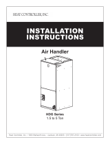
Haier HB2400VD1M20 User manual

Category
Split-system air conditioners
Type
User manual
SERVICE MANUAL
ƽ
Features
zHigh efficiency design
Models
Central Air Conditioning
zSplit-packaged design
z
zOptional electric heater
z
Convenient for installation and maintenance
z
Fully insulated and durable cabinet
Easily filter replacement
HB2400VD1M20
HB4800VD1M22
HB3600VD1M22
Manual code: SYJS-034-06REV.1 Edition: 2006-11-12
HB6000VD1M22(-E)
HB6000VD1M22
2
CONTENTS
1. DESCRIPTION OF PRODUCTS & FEATURES……………………..3
2.PHYSICAL AND ELECTRICAL SPECIFICATIONS……………….....4
3.SAFETY PRECAUTION…………………………………………….……5
4.ELECTRICAL CONTROL DEVICES…………………………….……..5
5.APPLICATION…………………..……………………………………..….5
6.INSTALLATION INSTRUCTIONS………………………....……………7
Central Air Conditioning Model: Air Handler, HB-D series
7.WIRING DIAGRAMS……………………………….…………………….17
3
1.2 Nomenclature for model number
Example
1. DESCRIPTION OF PRODUCTS & FEATURES
This manual discusses ‘split’ central air conditioning and indoor coils. “Split” central air condition
system refers to the physical location of major air conditioning components. The split system air
conditioning are manufactured to standards of quality and performance.They are 13 SEER(Seasonal
Engery Efficiency Ratio) which meet or exceed the standards imposed by efficiency legislated and
therefore represent both good value today and for years to come. The current air conditioning system
needs less external protection, while increasing the unit efficiency in cooling mode.
HV1M
Haier Blower unit
Nominal
capacity in
Electric
heater
Electric
Designation
Coil code
Design
series
Airflow
configuration
Unit
Width(in.)
Continuation
Brand
symbol
B:Blower unit
C:Evaporator
W:Wall moun
-ted unit
24:
24000BTU/h
00: No;
05: 5KW;
Y:575V-3Ph-60Hz;
V:208/230V-1Ph-
60Hz;
C:208/230V-3Ph-
60Hz;
D:460V-3Ph-
60Hz;
A:115V,1 Ph,60Hz
A:10 SEER
A/C coil
A/C coil
A/C coil
1: 1st
2: 2nd
Generation;
M:Multi-
direction
V:Vertical
H:Horizontal
17:17”[432]
20:20”[497]
22:22”[559]
25:25"[625]
paint
30:
30000BTU/h
08: 8KW;
10:10KW
Table 1-1
P: Powder
(1000) Btu/h
B00 D60 22 E
1.1 Air conditioning
use scroll and reciprocating compressors. This gives the air conditioning a durable compressor which
D:13 SEER Generation;
E:14 SEER
E: EC motor
Central Air Conditioning Model: Air Handler, HB-D series
3.SAFETY PRECAUTIONS
4.ELECTRICAL CONTROL DEVICES
THERMOSTATS
e
n
RELAYS
HEATER CONTACTOR
5. APPLICATION
which controls the heater.
The coil uses 24 volts but the contacts carry line voltage .The heater contactor is a large relay,
There are similar overloads in the indoor air handling portion with the electric resistance heaters. The
NOTE: Never disconnect or wire around a safety device. First determine why it opened, then replace it
with a properly rated part.
indoor blower motor has an internal overload. The electric elements use two types of protectors, both
protector and must be replaced upon opening. Limit controls are thermal discs that automatically reset.
replaceable. Some electric heat sections use fusible links. They are a one time over-temperature
Normally, limit controls open and stop the temperature rise before the fusible links open.
OVERLOADS AND LIMITS
ƽ Follow the manufacturer’s instructions when making repairs, installing replacement parts and
ƽ Use only authorized factory parts.
ƽ Always use industry-recognized service practices in the maintenance, adjustment and repair of the
products covered in this manual.
ƽ Always wear safety glasses when handling refrigerant and peforming brazing operations.
CAUTION: please read all instructions prior to
installing, operating, maintaining or repairing the
product.
WARNING: THE MANUFACTURER’S WARRANTY DOES NOT COVER DAMAGE TO CAUSED BY
THE USE OF ANSUTHORIZED COMPONENTS OR ACCESSORIES, THE USE OF SUCH
UNAUTHORIZED COMPONENTS OR ACCESSORIES MAY ENDANGER LIFE AND
OR INJURY RESULTING FROM THE USE OF SUCH UNAUTHORIZED COMPONENTS OR
PROPERTY. THE MANUFACTURER DISCLAIMS ANY RESPONSIBILITY FOR SUCH LOSS
ACCESSORIES
performing system maintenance.
In the cooling mode, the thermostat calls for cooling by energizing the compressor contactor and the
indoor blower control. The indoor blower can operate continuously by setting the thermostat subbase fan
switch to the “ON” position.
subbase selection information found in the wiring diagram booklet.
various manual changeover, auto changeover and set-back thermostats or see the thermostat and
accessible by the consumer. Contact your local distributor for information on part numbers of
Thermostats are the most obvious control in the air conditioning system because these controls are
Generally relays used in air conditioning use 24VAC coils. Contact voltage may be either low or line voltage.
Relays provide a method for control switching. Relays may switch either low(24VAC) or line voltage.
Before specifying any air conditioning equipment, a survey of the structure and a heat gain calculation
The cooling load calculation determines the unit size. There are two capacities that enable the
must be made. A heat gain calculation involves identifying all surfaces and openings that gain heat from
the surrounding air and quantifying that heat gain. The heat calculation also calculates the extra
heaty load caused by sunlight and by humidity removal. These factors must be considered before
selection an air conditioning system to provide year round comfort. The Air Conditioning Contractors
cooling load.
of America (ACCA) J Manual method of load calculation is one recognized procedure for determining the
Sensible heat is the heat energy
measured on the dry bulb thermometer.
equipment to provide comfort. The first is sensible capacity.
5
Central Air Conditioning Model: Air Handler, HB-D series
.
After the proper equipment combination has been selected, satisfying both sensible and latent
ƽ Outdoor unit location
ƽ Proper equipment evacuation
ƽ Outdoor unit refrigerant charge
ƽ Indoor unit air flow
ƽ Indoor unit blower speed
ƽ Supply and return air duct design and sizing
ƽ System air balancing
ƽ Diffuser and return air grille location and sizing
The second form of heat is called latent heat. This is heat held by the moisture in the air. Removing
this moisture does not affect a thermometer. However, removing the latent heat in the air greatly increase
comfort. A properly sized unit removes both forms of heat, producing a comfortable conditions,
An oversized system cycles on and off quickly and does not properly remove humidify, producing
uncomfortable. The indoor and outdoor equipment combination should be matched by the manufacturer
There are several factors that installers must consider.
and based on engineering data.
conditioning requirements, the system must be properly installed. Proper installation with cerefully
distributed air through adequate duct work will provided a comfortable living space.
and humidity control depend on the correct balance between indoor load and outdoor unit capacity. High
Air conditioning requires a specified air flow. Each ton of air conditioning requires 400 cubic feet of air
per minute (400CFM/TON).
of 3ein the return duct and 4ein the supply duct. This can reduce the cooling capacity of an air
conditioning system by as much as 30%.This means a loss of almost one ton of cooling capacity from a
three ton system.
Air leakage of only 3% in a return duct can cause a 5% loss in system capacity. 3% leakage on a three
Duct systems installed in the conditioned space can be left uninsulated , but a dense 1/2” fiberglass duct
liner reduces blower and air noises, and prevents sweating ducts when humidity levels are high.
Supply and return duct systems in attics and crawl spaces require a minimum 1” of dense duct liner or 2”
fiberglass wrap with a sealed vapor barrier. A leaky vapor barrier results in duct sweating, causing wet
The air distribution system has the greatest effect. On the quality of the installation and the owner satisfaction,
The correct air quantity is critical for correct air conditioning system. Proper operation, efficiency, compressor life
performance and customer's satisfaction and can cause premature component failure.
Duct design and construction should be done with care. System performance can be lowered
Effective duct insulation is essential to prevent loss of capacity and sweating ducts in the cooling mode.
dramatically through bad planning or workmanship. In cooling, a hot attic can cause a temperature gain
ton system is only 30 CFM. Two or three unsealed joints can cause a leak of this size. Sealing the return
and supply ducts result in full system capacity and lower operating costs.
the duct system is totally in the responsibility of the contractor. These are numerous thchnical associations
Low indoor air flow reduces total capacity, and can causes coil icing. Improper air balance will affect system
and reference that recommend correct procedures.
indoor air flow reduces system dehumidification capacity, and can leave the space humid and uncomfoltable.
insulation
does not insulated.
Air supply diffusers must be selected and located carefully. They must be sized and positioned to deliver
Heat transfer through poorly insulated systems can result in over 50%
loss in operating capacity. Sweating
ducts also results in rusting that leads to premature duct failure. Carefully follow the industry practices to
insure a well designed duct system.
treated air along the perimeter of the space. If they are too small for their intended air flow, they can be
noisy. If they are not located properly, they can cause drafts in the rooms. Return air grilles
must be
properly sized to carry air back to the blower. If they are too small they also cause noise. The installers
ensures a comfortable living space.
should balance the air distribution system to ensure proper air flow to all rooms in the home. This
6
Central Air Conditioning Model: Air Handler, HB-D series
6. INSTALLATION INSTRUCTIONS
! WARNING
adjustment and operation of this unit. Read these instructions thoroughly before attempting installation or
These instructions are intended as an aid to qualified, service and instalolation personnel for proper installation
service this equipment. Failure to follow these instructions may result in improper installation,
service or maintenance and could possibly result in fire, electrical shock, property damage,
personal injury or death.
This product is designed and manufactured to permit installation in accordance with National Codes. It is
prevailing local codes and regulations. The manufacturer assumes no responsibility for equipment
installed in violation of any codes or regulations.
The United States Environmental Protection Agency (EPA) has issued various regulations
may harm the environment and can lead to the imposition of substantial fines. Because these regulations
You should be aware that the use of
unauthorized components, accessories or devices may
adversely
affect the operation of the air
conditioner and may also endanger life and property.
The manufacturer disclaims any responsibility
regarding the introduction and disposal of refrigerants from this unit. Failure to follow these regulations
the installer's responsibility to install the product in accordance with National Codes and/or
are subject to revision any repair on this unit should be done by a certified technician.
The manufacturer's warranty does not cover any damage failure caused by the air conditioning system.
components, accessories or devices.
for loss or injury due to the use of such unauthorized
Attach the service panel to the outdoor unit after to prevent.
If the service panel is not attached securely, it
could result in a fire or an electric shock due to dust,
water, etc.
INDOOR COIL MAINTENANCE
Inspect the indoor coil at least once a year for cleanliness and clean as necessary.
1. The coil can be cleaned when dry. If it is coated with lint or dirt, blow compressed air or
nitrogen (NEVER USE REFRIGERNAT) through the supply air side of the coil fins. Place a sheet of
metal or cardboard under the return air side of the coil to catch any debris before it gets into the air
handler.
2. If the coil is coated with oil or grease, clean with a mild detergent and water solution. Rinse
3.
and flush with clear water.
4.
WARNING: DO NOT USE CAUSTIC HOUSEHOLD DRAIN CLEANERS IN THE CONDENSATE PAN
thoroughly with clear water. Be careful not to get water into the air handler.
High pressure watercan be used to clear any clog in the condensate line.
After cleaning the coil, inspect the drain pan and condensate line. Remove any debris from the pan
OR NEAR THE INDOOR COIL. THESE DRAIN CLEANERS CAN QUICKLY DAMAGE THE INDOOR COIL.
7
Central Air Conditioning Model: Air Handler, HB-D series
UNIT DIMENSIONS
a. For HB2400VD1M20 air handler
8
Central Air Conditioning Model: Air Handler, HB-D series
b. For HB3600VD1M22 air handler
9
Central Air Conditioning Model: Air Handler, HB-D series
c. For HB48/6000VD1M22 air handler
10
Central Air Conditioning Model: Air Handler, HB-D series
entire unit with a separate drain line properly sloped and terminated in an area visible to the owner. This
insulation should be applied to the drain lines in unconditioned spaces where sweating may occur.
elevated or located out of the normal path of vehicles. When installed on a base, the base must also be
protected by similar means.
AIRFLOW ORIENTATION
Before installing the air handler insure that it is properly sized and that adequate power is available.
This air handler can be installed in the vertical or right horizontal position without modification.
The horizontal left and downflow positions require product modification.
This product is designed for zero inch (0") clearance; however, adequate access for service,
maintenance or replacement must be considered beffor installation. This unit can be installed on a
secondary drain pan is required in the event that there is a leak or main drain blockage. Closed cell
service stand or return air properly as necessary.
In an attic installation, a secondary drain pan must be provided by the installer and placed under the
damage must be suitably guarded against such damage by installing behind protective barriers, being
Install air handlers in garages, warehouses or other areas where they may be subjected to mechanical
Heating and cooling equipment located in garages, which may generate, spark or flame capable of
When more than one air handler is installed in a building, permanently identify the unit as to the
igniting flammable vapors, must be installed with the ignition source at least 18" above the floor level.
area or space serviced by that air handler.
Important:
or downflow applications, and
install insulation kit on vertical
( donut shape ) drain pan.
*Upflow Discharge
It is recommendded that the horizontal
pan be removed when air handler is
installed in unconditioned space,
*Horizontal Right Discharge (Standard)
Horizontal Left Discharge (Optional)
Condensate drain conn. and refrigerant conn. on front,
Note auxiliary drain pan is under coil position.
Reloation of drain pan required see below
Fig.6-4
11
Central Air Conditioning Model: Air Handler, HB-D series
1) With Air handler in the vertical position, remove all three access panels.
4) Knockouts are located within the drain assemblies .Carefully remove only the correct knockouts using
a hammer and screw driver for each application, making sure the primary and secondary drains are
Static pressure
CFM
MODEL
L 630 614 599 585 571 556 536 515
H 900 877 856 835 816 795 766 737
L --- 1125 1093 1062 1033 1006 976 946
H --- 1240 1208 1177 1148 1121 1091 1061
L --- 1480 1442 1404 1366 1328 1290 1252
H --- --- 1650 1605 1560 1515 1470 1425
HB6000VD1M22
H --- --- 1800 1745 1690 1635 1580 1525
HB6000VD1M22-E
H --- --- 1850 1795 1740 1685 1630 1575
HB4800VD1M22
0.25 0.30 0.35
Indoor
fan
speed
0.1 0.15 0.20
TABLE 8-4 Airflow for 13SEER air handers
0.50
HB2400VD1M20
HB3600VD1M22
0.40
left-hand side.
6) Replace the J-shape metal bracket or brackets on the vertical drain pan and place the
over torque screws. Snap in the drain cover on the right lower service panel.
Air handler must be leveled and then pitched 1/4" toward drain side. Important:
Drain pan must be
HORIZONTAL LEFT-HAND INSTALLATION
Instructions: Follow steps below carefully to modify air handler for left hand.
open and clear of burrs and debris. Remove secondary drain knockout only if this drain is required by
bracket at the rear of the cavity
.
cal codes and practices.l
local codes and practices.
WARNING: If incorrect knockouts are removed, water damage could occur.
Note: Push the assembly completely to the rear of the cavity and assure it slips into channel
Fig.6-5
2) Remove J-shape metal bracket holding coil pan in place. Slide out the "A" coil pan assembly from
pan drain and also remove the plastic drain cover from the lower left access panel. Fig. 6-5
the air handler cavity with horizontal drain pan on the right side. Remove oval gasket from horizontal
3) Relocate horizontal pan on the left-hand side of the "A" coil assembly.
5) Reinstall the "A" coil pan assembly in the Air handler with the horizontal drain pan on the
7) The Air handler can now be placed in its left horizontal position as shown in Fig.6-6. The
tested for proper drainage by pouring water into the pan. Traps must be installed on both the primary drain
plastic oval gasket on horizontal drain pan. Reinstall access panels and flowrator making sure not to
and the secondary drain if used.
12
Central Air Conditioning Model: Air Handler, HB-D series
8) In all cooling applications, a secondary drain pan must be provided by the installer and
9)Before setting up flowrator assembly for field brazing see page 12 or read the Warning
label on the lower access panel
.
placed under the entire unit with a separate drain line properly sloped and termina t e d as required by
10) Incorrect installtion or improper practices could affect the product warranty.
local codes.
Note: the *M22 units can be installed as upflow discharge.
Fig. 6-6
13
Central Air Conditioning Model: Air Handler, HB-D series
DOWNFLOW INSTRUCTIONS
Important: Read instructions below carefully
1. Before putting the Air Handler in the downflow position, remove the three access panels and remove
the metal coil retaining bracket and filter close off. Then remove the horizontal and vertical drain pans.
The horizontal pan is not required for downfolw application.
2. After removing the coil, turn the Air Handler to the downflow position and relocate the (8) brackets
which include (1) tie bracket (1) rear channel brackets, (2) zee coil supports, (2) stiffener brackets, and (2)
3"2 flat insulation retaining brackets. In effect, brackets, coil and 2 lower access panels will be assembled
180 degrees from their former position and shifted down with return in up position as shown in fig.1 and
fig. 2.
3. Assemble drain pan insulation kit to the bottom o
f the drain pan to prevent drain pan from sweating
during operation.
4. Place 3" flat insulation retainer on the bottom o
f each coil slab against the aluminum fins as shown in
Fig.3. This will reduce the potential for water blow-off into the air stream.
5. Slide the coil assembly into Air Handler and reattach the metal coil retainer bracket to tie
bracket. See Fig.2. Then reattach the upper acceses anel followed by the two lower access
panels to match the tubing and drains.
6. A 4" to 3" removable panel is recommended at the point where the duct meets with the return part of
the Air Handler unit to allow easier removal of coils that are too tall.
7. The "HB" coils are shipped with a check flowrator for use with either cooling or heat pump outdoor
section which is accessible from the outside of the unit.
WARNING: The "A" coil contains 150 p.s.i.g. of air pressure
Fig . 3
REFRIGERANT TUBING
CONDENSATE REMOVAL
The total workable height of this trap, in inches, must exceed the total negative pressure,
in inches of water, as measured in the return duct.
THIS AIR HANDLER EMPLOYS A DRAW-THROUGH COIL, THEREFORE A LIQUID SEAL
TRAP MUST BE INSTALLED IN THE DRAIN LINE(S) TO ALLOW FOR OR PROPER
CONDENSATE REMOVAL.
The condensate trap must be a "P " trap as shown bellow.
The condensate drain line must be at least 3/4 NPT, for each unit. Use caution when tightening the
adapter at the drain pan connection, to prevent damage to the plastic drain pan. A joint compound
should be used to prevent leakage and act as a lubricant.
Refrigerant tubing should be installed so that it is properly supported, sized and sloped. The vapor
sealed. The insulation should terminate at the tubing entrance to the air handler. Do not reduce
and liquid lines must be supported or routed to avoid strain or vibration. To avoid damage that can
be caused by condensation, insulate the suction tube with a closed cell insulation with the seams
the recommended tubing size.
Fig..6-7
Fig.6-
8
Central Air Conditioning Model: Air Handler, HB-D series
14
adequately insulated.
The unit and the auxiliary drain pan must be adequately elevated to insure proper drainage.
ELECTRICAL CONNECTIONS
When an optional heat kit is installed refer to the electrical requirements in that kit.
The wiring diagram included in the heat kit must be placed over
the wiring diagram on the air handler.
Air Handler as indicated.
Table 6-1 Electrical parameter
The required electrical power supply information is located on and rating plate on the exterior of the unit.
Copper wire is recommended for all electrical connections.
Wiring selection must be in accordance with local codes, or in absence of local code, the National
All pertinent information, such as the rating plate, included in the optional heat kit must be applied to the
Electrical Code. A disconnect means should be installed within sight of the unit, as required by code.
When copper tubing is uesed for the condensate line, adequate caution must be taken to prevent damage
to the plastic drain pan during the soldering process. All condensate drain lines and drain traps should be
Use of a condensate removal pump may be necessary. This condensate pump should have provisions
for shutting off the control voltage should a blockage in the drain line or condensate pump failure
contain any of these materials.
occur. A trap must be installed between the unit and the condensate pump.
Important: The evaporator coil may have residual oils that could dissolve Styrofoam and certain types
of plastics. Therefore a removal pump or float switch must not
The use of copper connections are recommended for all modification or field supplied accessories inside
the air handler electrical section inside the control box.
Central Air Conditioning Model: Air Handler, HB-D series
15
Model(indoor units)
Min. ampacity
208/230V
Max.Overcurrent(A)
208/230V
Fan motor
capacitor(UF)
Blower motor
FLA
Blower
motor HP
HB2400VD1M20 1.1 15/15 8 0.9 1/8
HB3600VD1M22 2.5 15/15 8 2.0 1/3
HB4800VD1M22 3.3 15/15 8 2.6 1/2
HB6000VD1M22 4.4 15/15 12 3.5
3/4
HB6000VD1M22-E 5.0 15/15
/ 4.0 3/4
When an optional electric heat kit is installed refer to the electrical requirements for that kit. The
ampacity and over-current protection shown above is only
for "HB" air handlers installed without
a heat kit
.
Port definition:
C1, C2: power input port, 24VAC;
C3: control signal input port, 24V;
P1, P2, P3: fan motor control port --- P1 is COM port, P3 is normal OFF, P2 is normal OPEN;
K1: fan motor relay
Function description
1. K1 will open 15 seconds later after there is 24V signal from C3;
2. K1 will open 30 seconds later after there is no signal from C3;
3. AC contactor control the electric heater solely.
Connecte P1 with netural wire of fan motor, connect normal OPEN port P2 with power input
port of AC contactor, supply P1 the power of fan motor when there is signal from C3. connect
normal OFF port P3 with power output port of AC contactor, to ensure the fan motor work
whenever there is or is not control signal during heater woring.
C1
C2
C3
P1
P2
P3
K1
Electric control function for air handlers
A MEANS OF STRAIN RELIEF TO PROTECT THE ENTRY BLOCK WIRE CONNECTION.
Central Air Conditioning Model: Air Handler, HB-D series
16
7. WIRING DIAGRAM
2
BK-HI
1) Confirm system selection. Optional components may be field or factory installed.
2) For proper system operation, consult indoor unit and outdoor unit installation instructions to confirm
system match up and blower speed selection.If the motor have only one capacitor wire,connect Com line to
capacitor.
3) Indoor unit shipped without optional electric heater kit. To install optional heater kit, remove power pig
tail up to 9 pin plug. Install heater kit and connect with mating 9 pin plug. Run system power connections
directly to electric heater kit power terminals. Consult heater kit installation instructions for complete
details.
W
BK - BLACK BL - BLUE GY - GRAY
BR - BROWN GR- GREEN OR - ORANGE
PU - PURPLE RD - RED VI - VIOLET
WH - WHITE YL - YELLOW
R
C
HEAT CONTROL
INDOOR FAN CONTROL
G
RESISTANCE
Y
L2
RD
OR
RD-LO
RD
BK
L1
BK
RC
RD
BL
BR
G
W2
W
WH
BL
COM
208
BL
230
TRAN
RD
CA
SW-2
LED
RHS-1
ON
AUTO
RHS-2
COOL
OFF
TS
FAN
HEAT
SW-1
HEAT
HA
COOL
OFF
Air Handler Wiring Diagram
BCR - BLOWER CONTROL RELAY
BCAP - RUN CAPACITOR BLOWER MOTOR
BTD - BLOWER TIME DELAY
IBM - INDOOR BLOWER MOTOR
TRAN - TRANSFORMER
230/208 SELECTABLE
USE COPPER CONDUCTORS ONLY
WARNING CABINET MUST BE PERMANENTLY GROUNDED
AND ALL WIRING TO CONFORM TO I.E.C.,N.E.C.,C.E.C.,
C.L.C. AND LOCAL CODES AS APPLICABLE.
REPLACEMENT WIRE MUST BE THE SAME GAGE AND
INSULATION TYPE AS ORIGINAL WIRE.
LINE VOLTAGE
FACTORY STANDARD
FIELD INSTALLED
OPTIONAL
LOW VOLTAGE
FACTORY STANDARD
FIELD INSTALLED
OPTIONAL
60Hz 1PH
BCAP
IBM
R
PU
BR
M
S
BR
GND
L1
L2
WH
BK
BL
GR
2
2
1
BCR
1
BK
6
3
4
5
BR
3
4
5
PU
RD
BL
6
WH
3
208/230V
UNIT
INDOOR
TL
RD
BL
4
RD
3
2
1
PU
BK
L2
RD
6
5
BR WH
RD
RD
TL
OPTIONAL
ELECTRIC HEATER KIT
BRK
L1
FL
BK
BK
FL
BK
BK
1
RD
RD

COLOR CODES
COMPONENT CODES
P1
P2
P3
C3
C2
C1
RD
Central Air Conditioning Model: Air Handler, HB-D series
17
Sincere Forever
Haier Group
Haier Industrial Park, No.1, Haier Road
266101, Qingdao, China
http://www.haier.com
Central Air Conditioning Model: Air Handler, HB-D series
  • Page 1 1
  • Page 2 2
  • Page 3 3
  • Page 4 4
  • Page 5 5
  • Page 6 6
  • Page 7 7
  • Page 8 8
  • Page 9 9
  • Page 10 10
  • Page 11 11
  • Page 12 12
  • Page 13 13
  • Page 14 14
  • Page 15 15
  • Page 16 16
  • Page 17 17
  • Page 18 18

Haier HB2400VD1M20 User manual

Category
Split-system air conditioners
Type
User manual

Ask a question and I''ll find the answer in the document

Finding information in a document is now easier with AI