Page is loading ...

Installation and Operation Manual for
the SBIII Digital Signal Booster
Model 613-8 (with G1A or G2A mounting)
DIGITAL TECHNOLOGY
WARNING: This is NOT a consumer device. It is designed for installation by FCC Licensees and Qual-
ified Installers. You must have an FCC license or express consent of an FCC Licensee to operate this
device. This booster can be configured as either a Class A or Class B signal booster. If configured as a
Class B signal booster (as defined in 47 CFR 90.219), you MUST register this signal booster online at
www.fcc.gov/signal-booster/registration. Unauthorized use may result in significant forfeiture penalties,
including penalties in excess of $100,000 for each continuing violation.
Manual
Part #
7-9603-1


DISCLAIMER
Pro
duct part numbering in photographs and drawings is accurate at time of printing. Part number labels on Bird
products supersede part numbers given within this manual. Information is subject to change without notice.
TERMS AND CONDITIONS OF SALE
3OHDVHYLVLWWKH%LUGZHEVLWHIRUFRPSOHWHLQIRUPDWLRQUHJDUGLQJWHUPVDQGFRQGLWLRQVDQGZDUUDQW\
LQIRUPDWLRQ
http://www.birdrf.com/~/media/Bird/Files/PDF/Sales/bird-terms-and-conditions-of-sales.ashx

Bird Manual 7-9603-1 08/09/17 Page 3
NOTE
VIDEO
WARNING
CAUTION or ATTENTION
Important Information
Training Video Available
Electrical Shock Hazard
ESD Electrostatic Discharge
Hot Surface
High Voltage
Symbols Commonly Used
Manual Part Number 7-9603
Copyright © 2018 Bird
First Printing: August 2017
Version Number Version Date
1 08/09/17

Bird Manual 7-9603-1 08/09/17 Page 4
Changes to this Manual
We have made every effort to ensure this manual is accurate. If you discover any errors, or if you have suggestions
for improving this manual, please send your comments to our Solon, Ohio facility to the attention of the Technical
Publications Department. This manual may be periodically updated. When inquiring about updates to this manual
refer to the manual part number and revision number on the revision page following the front cover.
DIGITAL TECHNOLOGY

Bird Manual 7-9603-1 08/09/17 Page 5
Table of Contents
Overview...............................................................................................................9
SBIII Options......................................................................................................10
Down / Up Conversion.......................................................................................11
Unpacking ..........................................................................................................11
Installation..........................................................................................................11
Location ...........................................................................................................13
Mounting ...........................................................................................................13
Cable Connections ...........................................................................................13
AC Line Connection.......................................................................................13
DC Power Connection ...................................................................................13
Alarm Connections ........................................................................................13
NFPA Compliance .........................................................................................15
RF Connections .............................................................................................16
Pre-RF Connection Test ....................................................................................16
Antenna Isolation .............................................................................................17
Required Equipment .......................................................................................17
Measurement Procedure.................................................................................17
RF Exposure (Exposition RF) ..........................................................................18
Signal Flow Block Diagram ..............................................................................18
Uplink and Downlink Input Signals (Single-band Booster) ................................19
Uplink and Downlink Input Signals (Dual-band Booster) ...................................19
Channel Module.................................................................................................19
Uplink and Downlink Output Signals (Single-band Booster)..............................19
Uplink and Downlink Output Signals (Dual-band Booster) ................................20
System Setup .....................................................................................................20
Operation............................................................................................................20
Communicating with the Booster ....................................................................21
System Summary Submenu ..............................................................................22
Control Panel Submenu.....................................................................................22
Filters Tab........................................................................................................22
Filter Detail Tab ...............................................................................................23
Design Button ................................................................................................24
Status Area ....................................................................................................25
Link Tab ...........................................................................................................25
Command Buttons ..........................................................................................25
Link and Settings Area ....................................................................................26
Status Area .....................................................................................................27
System Tab .......................................................................................................28
Oscillation Detection .......................................................................................28
Class B Enable................................................................................................28
Network Configuration Submenu ......................................................................28
User Administration Submenu ..........................................................................28
SNMP Configuration Submenu .........................................................................29
Initial SNMP Setup ..........................................................................................30
SNMP Manager Example................................................................................31
Creating an Alarm for Testing Purposes .......................................................31
Maintenance .......................................................................................................32
Power Amplifier Replacement ...........................................................................32
Channel Module Replacement ..........................................................................33
Control Module Replacement ............................................................................34
Power Supply Replacement ..............................................................................35

Bird Manual 7-9603-1 08/09/17 Page 6
Figures and Tables
Figure 1: The Down / Up Converter Process .....................................................11
Figure 2A: Cabinet Mounting (Single-band Booster) .........................................12
Figure 2B: Cabinet Mounting (Dual-band Booster) ...........................................12
Figure 3: Booster Cabinet Front View.................................................................14
Figure 4: AC/DC Circuit Breakers.......................................................................15
Figure 5: The Remote Antenna Line Sensor ......................................................16
Figure 6: Enclosure RF Connections..................................................................16
Figure 7: Measuring Antenna Isolation ...............................................................17
Figure 8: Signal Flow Block Diagram (Single-band Booster)..............................18
Figure 9: Signal Flow Block Diagram (Dual-band Booster) ................................19
Figure 10: Control Board.....................................................................................20
Figure 11: System Summary Submenu..............................................................22
Figure 12: Filter Summary Tab ...........................................................................23
Figure 13: Class A Limit Exceeded Warning Message.......................................23
Figure 14: Filter Detail Tab..................................................................................24
Figure 15: Invalid Filter Settings Warning Message ...........................................24
Figure 16: Design Filter Interactive Display ........................................................25
Figure 17: Link Tab .............................................................................................26
Figure 18: System Tab........................................................................................27
Figure 19: Starting Class B Operation Message ................................................28
Figure 20: Network Configuration Submenu.......................................................29
Figure 21: The Admin Submenu.........................................................................29
Figure 22: SNMP Configuration Submenu .........................................................30
Figure 23: SNMP Manager Example ..................................................................32
Figure 24: Removing the Power Amplifier...........................................................33
Figure 25: Removing the Channel Module .........................................................34
Figure 26: Removing the Power Supply..............................................................35
Table 1: Model number nomenclature...................................................................9
Table 2: Specifications ........................................................................................10
Table 3: Subassembly LED Descriptions ............................................................21
Appendixes
Appendix A: Ethernet Connectivity ....................................................................36
General Description .............................................................................................36
Direct Connection ..............................................................................................36
Required Equipment ........................................................................................36
Procedure ........................................................................................................36
Networked Connection ......................................................................................37
Required Equipment ........................................................................................38
Procedure ........................................................................................................38
Appendix B: Optional Fiber Optic Interface........................................................39

Bird Manual 7-9603-1 08/09/17 Page 7
For Class A or Class B Unintentional Radiators
This equipment has been tested and found to comply with the limits for a Class A or Class B digital device, pursuant to
Part 15 of the FCC rules. These limits are designed to provide reasonable protection against harmful interference when
the equipment is operated in a commercial environment. This equipment generates, uses, and can radiate radio fre-
quency energy and, if not installed and used in accordance with the instruction manual, may cause harmful interfer-
ence to radio communications. Operation of this equipment in a residential area is likely to cause harmful interference
in which the user will be required to correct the interference at his own expense.
Pour Classe-A ou Classe-B Radiateurs Involontaires
Cet équipement a été testé et jugé conforme avec les limites de la Classe-A ou Classe-B des appareils numériques,
suivants à la Partie 15 des règlements de la FCC. Ces limites sont conçues pour fournir une protection raisonnable
contre les interférences dangereuses lorsque l'équipement est utilisé dans un environnement commercial. Cet équipe-
ment génère, utilise et peut émettre des fréquences radio et, s'il n'est pas installé et utilisé conformément aux instruc-
tions du manuel, ceci peut causer des interférences dangereuses aux communications radio. Le fonctionnement de cet
équipement dans une zone résidentielle est susceptible de causer des interférences mauvaises dans lequel l'utilisateur
sera tenu pour responsable de corriger l'interférence à sa propre discrétion.
WARNING: Changes or modifications which are not expressly approved by Bird could void
the user’s authority to operate the equipment.
AVERTISSEMENT: Les changements ou modifications qui ne sont pas approuvés par Bird
pourrait annuler l'autorité de l'utilisateur de faire fonctionner l'équipement.
ATTENTION: This device complies with Part 15 of the FCC rules. Operation is subject to the
following two conditions: (1) this device may not cause harmful interference and (2) this
device must accept any interference received, including interference that may cause undes-
ired operation.
ATTENTION: Cet appareil est conforme à la Partie 15 des règlements de la FCC. L'opéra-
tion doit se conformer aux deux conditions suivantes: (1) cet appareil ne peut causer d'inter-
férences nuisibles et (2) cet appareil doit accepter toute interférence reçue, y compris les
interférences qui peuvent provoquer un fonctionnement indésirable.


Bird Manual 7-9603-1 08/09/17 Page 9
OVERVIEW
Signal boosters extend radio coverage into areas
where abrupt propagation losses prevent reliable
communication. The system receives an RF signal,
raises its power level, and couples it to an antenna
so that it can be re-radiated. The Bird 613-8 family
of signal boosters is designed to operate in either
the 700 or 800 MHz range. Dual-band models are
available that include both 700 and 800 MHz sys-
tems in the same enclosure box. The system is
based on a module design with each module capa-
ble of handling 14 or 30 filters in the uplink and
downlink direction. The signal booster is available
in a variety of configurations as shown in Table 1.
The product model number is used to describe
each configuration available. Model number
nomenclature is described in table 1.
The size of the system can be tailored to the cus-
tomers needs by increasing or decreasing the
number of filters used. Each module is bi-direc-
tional with one downlink and one uplink signal
branch. Each of the two branches in a module are
independently tunable to their required pass fre-
quencies via software interface. The booster uses
digital processing techniques to provide a wide
613-8XX-YYUD-Z-O (nomenclature breakdown)
613 Designates product as 700 - 800 MHz channelized signal booster
8XX
Designates operating frequency band
3B = 764 - 806 MHz
9A = 806 - 869 MHz
3E = 764 - 869 MHz
YY
Designates how many modules are used and number of filters available
A = 1 x 14 (700 MHz) or (800 MHz) filter
B = 1 x 30 (700 MHz) or (800 MHz) filter
AA = 1 x 14 (700 MHz) filter and 1 x 14 (800 MHz) filter
BB = 1 x 30 (700 MHz) filter and 1 x 30 (800 MHz) filter
AB = 1 x 14 (700 MHz) filter and 1 x 30 (800 MHz) filter
BA = 1 x 30 (700 MHz) filter and 1 x 14 (800 MHz) filter
UD
Designates the type of output for the uplink and downlink
HH = High Power Uplink and Downlink
HL = High Power Uplink and Low Power Downlink
LH = Low Power Uplink and High Power Downlink
LL = Low Power Uplink and Downlink
FH = High Power Fiber Remote
FL = Low Power Fiber Remote
HF = High Power Fiber Head-end
LF = Low Power Fiber Head-end
Z
Designates mounting style
G1A = Painted enclosure
G2A = Stainless steel enclosure
Options
Designates the options that have been added
Blank = no options added
N = NFPA/IFC Configuration
H = Head-end booster (Dual Port)
R = Remote-end booster (Dual Port)
1 = 3 MHz Preselector, NPSPAC Pre-Rebanding (866 - 869 MHz)
2 = 3 MHz Preselector, NPSPAC Post-Rebanding (851- 854 MHz)
3 = 10 MHz Preselector (851-861 MHz)
Table 1: Model number nomenclature.

Bird Manual 7-9603-1 08/09/17 Page 10
range of filter choices to the end user. It is possible
to program digital filters as narrow as 6.5 KHz and
as wide as 3.0 MHz centered at any frequency
within the licensed range.
The SBIII Digital Signal Booster is capable of oper-
ating as either a Class A booster (no filters greater
than 75 KHz passband width) or as a Class B
booster (having filters with a greater than 75 KHz
passband width). The boosters operating class (A
or B) is user determined via configuration. Class B
operation must be enabled by the customer and
the customer is responsible for registering a
booster operated as Class B with the FCC. System
specifications for the 613-8 family of signal boost-
ers are listed in Table 2.
SBIII Options
There are optional configurations available for the
SBIII booster as shown in table 1. Each of these
optional configurations must be installed in the
booster at the time of manufacture. A brief discus-
sion of each option is provided below.
N = With this option installed the booster is capable
of meeting NFPA/IFC compliance requirements. In
an NFPA compliant booster the alarm terminal
interface is expanded out to five sets of alarm con-
tacts. In addition, A bias-T circuit is installed in the
booster and a remote antenna line sensor is pro-
vided.
H = The antenna connection for the service side of
the booster is split into an individual uplink and
downlink connector. This allows the booster to
operate as the head-end in a multi-booster system.
This option is typically used when the booster is
connecting to a fiber optic transceiver. Extra filter-
ing is included in the booster as needed.
Parameter Specification
Frequency Range (MHz)
700 Band
800 Band
764 - 776 and 794 - 806
806 - 824 and 851 - 869
Filters 14 - 30 uplink filters per band
14 - 30 downlink filters per band
Maximum Gain * 95 dB
Filter Bandwidth
Programmable standard filters include 12.5 KHz,
12.5 KHz low delay, 25 KHz, 3 MHz, 9 MHz. Other
custom filters can be configured by the user or fac-
tory to meet specific system requirements.
Output Level
High Power
Low Power
+34 dBm
+22 dBm
Maximum Input Level -20 dBm
RF In/Out Impedance 50 Ohms Nominal
Alarms Form-C Contacts (NO or NC)
Power
90 - 250 VAC, 50/60 Hz
or
+24 VDC
Operating Temperature Range -30°C to +60°C
* Note:
The booster ships from the factory with the gain adjusted to 60 dB. The customer should adjust the gain higher only
after verifying there is sufficient antenna isolation. Refer to the section of this manual titled Antenna Isolation.
Table 2: System specifications.

Bird Manual 7-9603-1 08/09/17 Page 11
R = The antenna connection for the donor side of
the booster is split into an individual uplink and
downlink connector. This allows the booster to
operate as a remote booster in a multi-booster sys-
tem. This option is typically used when the booster
is connecting to a fiber optic transceiver. Extra fil-
tering is included in the booster as needed.
1= A 3 MHz preselector is included at the donor
antenna port. The preselector will be tuned at 866 -
869 MHz.
2 = A 3 MHz preselector is included at the donor
antenna port. The preselector will be tuned at 851 -
854 MHz.
3 = A 10 MHz preselector is included at the donor
antenna port. The preselector is tuned at 851 to
861 MHz.
Down / Up Conversion
A channelized signal booster has much in common
with a superheterodyne (superhet) receiver. The
incoming signal is converted to a lower frequency
so that single channel selectivity can be obtained.
It is then filtered. Unlike the superhet receiver how-
ever, the signal is not demodulated. Instead, it is
up-converted back to its original frequency where it
is further amplified to reach a useful power level.
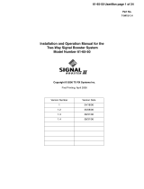
Figure 1 shows a simplified block diagram that
illustrates the down/up conversion principle. An
incoming signal at (Freq IN) is amplified and
applied to the first mixer along with a signal from a
local oscillator (Freq LO). A third signal at an inter-
mediate frequency (Freq IF) is produced as a result
of the mixing. The intermediate frequency is given
by the following relationship:
(1) Freq IF = Freq IN - Freq LO
The IF signal from the mixer then passes through
digital filtering with single channel bandwidth
before being amplified and passed on to the sec-
ond mixer. The second mixer also receives the
same local oscillator signal (Freq LO). The result is
a mixing product frequency at the output of mixer 2.
The output frequency (Freq OUT) is given by the
following relationship:
(2) Freq OUT = Freq IF + Freq LO
Substituting equation (1) for the “Freq IF” term in
equation (2) allows the “Freq LO” terms to be can-
celed yielding:
(3) Freq Out = Freq IN
The implication of equation (3) is that the frequency
stability of the signal that is processed by this type
of signal booster is not affected by the frequency
stability of the signal booster itself. Frequency sta-
bility depends only on the stability of the signal
source producing the signal to be boosted. A shift
in the LO frequency will cause the center of the fil-
ter bandwidth to move with respect to the signal.
For very narrow filter widths, the channel modules
LO may be locked to a high stability 10 MHz refer-
ence.
UNPACKING
It is important to report any visible damage to the
shipping company immediately. It is the customers
responsibility to file damage claims with the ship-
ping company within a short period of time (1 to 5
days). Care should be taken when removing the
unit from the packing box to avoid damage to the
unit.
INSTALLATION
The following sub-sections of the manual discuss
general considerations for installing the booster. All
Intermediate
Frequency
Signal
Processing
1st Mixer 2nd Mixer
RF OutRF In
Local
Oscillator
Figure 1: The down converter / up converter process.

Bird Manual 7-9603-1 08/09/17 Page 12
0.44 Dia
(2 places)
0.44 wide slot (2 places)
27.2424.00
10.00 8.78
16.00
Mounting Tabs
(4 Places)
Lockable Door Latch
(user supplied padlock)
Note: To open the door handle insert
a slotted screw driver into the silver
slot and turn to the vertical position.
At the same time turn the black han-
dle. This will release the latching
mechanism and the door can now be
opened. When the door is closed and
the black handle is turned down, the
silver slot will reset to the horizontal
position re-enabling the latching
mechanism.
Figure 2A: Cabinet mounting hole layout for single-band boosters.
0.44 Dia
(2 places)
0.44 wide slot (2 places)
33.2430.00
14.00 10.8
20.00
Mounting Tabs
(4 Places)
Lockable Door Latch
(user supplied padlock)
Note: To open the door handle insert
a slotted screw driver into the silver
slot and turn to the vertical position.
At the same time turn the black han-
dle. This will release the latching
mechanism and the door can now be
opened. When the door is closed and
the black handle is turned down, the
silver slot will reset to the horizontal
position re-enabling the latching
mechanism.
Figure 2B: Cabinet mounting hole layout for dual-band boosters.

Bird Manual 7-9603-1 08/09/17 Page 13
work should be performed by qualified personnel
and in accordance with local codes.
Location
The layout of the signal distribution system will be
the prime factor in determining the mounting loca-
tion of this unit. However, safety and serviceability
are also key considerations. The unit should be
located where it can not be tampered with by the
general public, yet is easily accessible to service
personnel. Also, consider the weight of the unit and
the possibility for injury if it should become
detached from its mounting for any reason.
The booster needs to be installed such that there
can be unobstructed air flow around the equip-
ment. Ensure that the heat sink fins are unob-
structed. The various subassemblies within the
equipment cabinet will stay warm during normal
operation so in the interest of equipment longevity,
avoid installation locations that carry hot exhaust
air or are continually hot.
Mounting
Figures 2A and 2B show the mounting hole
dimensions and layout for the single-band and the
dual-band enclosure. Mount the cabinet using 3/8”
(10 MM) diameter steel bolts (not supplied). We
recommend flat washers on both ends and a lock
washer under the nut. Nut and bolt mounting is
preferred to the use of lag bolts. Use backer blocks
where necessary to spread the force over a larger
area. In areas of known seismic activity, additional
devices such as tether lines may be necessary.
Because Bird cannot anticipate all of the possible
mounting locations and the structure types where
these devices will be located, we recommend con-
sulting local building inspectors, engineering con-
sultants or architects for advice on how to properly
mount objects of this type, size and weight in your
particular situation. It is the customers responsibil-
ity to make sure that these devices are mounted
safely and in compliance with building codes.
Cable Connections
All cabling connections to the booster should be
made and checked for correctness prior to power-
ing up the system. RF cables are connected at the
top of the booster cabinet while power (both AC
and DC) as well as alarm connections are made
inside the cabinet via conduit openings located at
the bottom or top of the cabinet.
AC LINE CONNECTION
The signal booster is designed to be hard-wired to
a single phase AC line supplying 90 - 250 VAC at
50/60 Hz. The power supply assembly used in the
booster is auto ranging so there is no voltage
select switch (110/240) on the power supply
assembly. Bring the AC line into the cabinet
through a conduit opening in the bottom or top of
the enclosure as shown in Figure 3. Connect the
hot and neutral wires to the input of the AC circuit
breaker and connect the earth ground wire to the
cabinet ground connection as shown in Figure 4.
Use conduit for running the AC wiring into the
enclosure and #14 gauge or larger conductors.
The AC feed line should have an independent cir-
cuit breaker (a 15 Amp breaker is recommended).
DC POWER CONNECTION
The booster may be run on a 24 VDC backup
power source. Bring the DC power line into the
cabinet through a conduit opening in the top or bot-
tom of the enclosure and connect the red (+) and
black (-) feed lines to the DC circuit breaker. Use a
conduit for running the DC wiring into the enclo-
sure. The booster will automatically switch to this
backup DC source when the AC supply fails for any
reason including a power outage or intentional dis-
connection. It is not necessary that the DC hookup
be made for normal booster operation on the AC
line.
ALARM CONNECTIONS
Alarm Form-C contact terminals are located on the
main mounting panel inside the enclosure as
shown in figure 4. These terminal contacts are
intended for connection to the customer’s supervi-
sory data acquisition system or a fire panel in the
case of an NFPA compliant signal booster system.
In a non-NFPA compliant signal booster two alarm
functions are available including Summed Alarm
and Loss of AC. In a fully NFPA compliant signal
booster three additional alarm functions are pro-
vided including Antenna Malfunction, Charge Fail,
and Low Battery.
The normal condition for the booster is power
applied, the booster operating as usual, and no
alarms occurring in the booster or the battery
backup unit. Under these normal conditions there
will be continuity between Com and NC alarm ter-
minal contacts and no continuity between the Com
and NO contacts. When an alarm condition occurs
the alarm terminal contacts will change state. The

Bird Manual 7-9603-1 08/09/17 Page 14
Figure 3: Front view of the typical booster with the door removed for clarity.
Downlink IN
Uplink OUT
(to Donor Antenna)
Uplink IN
(to Service Antenna)
Power
Supply
Assembly
Alarm
Ter min a l s
Conduit
Opening
Conduit
Opening
Filter
Channel
Module
Filters
Control
Board
AC/DC
Line
Filters
AC/DC
Breakers
Chassis
Ground
Downlink OUT
(to Service Antenna)
Conduit
Opening
Power
Amplifier
Channel
Module
2-Way
Divider
2-Way
Divider
Conduit
Opening

Bird Manual 7-9603-1 08/09/17 Page 15
alarm terminal strip uses screw terminals for ease
of connection. Route the alarm wires through one
of the conduit openings at the top or bottom of the
enclosure, strip about 3/16” of insulation from the
end of each wire and attach to the appropriate ter-
minal screw. Alarm connections should be made
with suitable hook-up wire typically between #20 to
#22 gauge and in accordance with any local wiring
codes.
NFPA COMPLIANCE
The signal booster is designed to be compliant with
the national public safety in-building codes issued
in the International Fire Code and by the National
Fire Protection Association. The booster accom-
plishes compliance when used in conjunction with
an appropriate battery backup unit. An optional
battery backup unit is available from Bird including
the models 6160-110-24-NR and the 6160-220-24-
NR battery backups. Detailed installation and oper-
ating instructions for the battery backup unit are
included with the backup unit when it ships from
the factory.
An NFPA compliant signal booster system is
designed to easily interface to fire alarm panels.
Five alarms are provided including SB Failure
(FAIL), Loss of AC Power (AC), Charge Fail (CHG),
Antenna Malfunction (ANT), and Low Battery
Capacity (BAT). These five alarm functions are
available at the terminal contacts shown in figure 4.
The terminals provide a common access point to
the alarm signal relay contacts. Available alarm
functions include;
SB Failure - this is a summed alarm that is active
when any number of fault conditions arise within
the booster unit such as when an over current or
high temperature event occurs.
Loss of AC Power - indicates that AC power to the
booster unit has failed.
Low Battery Capacity - the source of this alarm is
the battery backup unit and it indicates that the bat-
tery backup voltage level has dropped significantly.
Charge Fail - the source of this alarm is the battery
backup unit and it indicates failure of the battery
charger. If the battery charger looses AC power
this alarm will be active.
Antenna Malfunction - indicates there is a loss of
RF cable integrity between the signal booster unit
and the remote antenna line sensor. In order to
detect an antenna malfunction an antenna line
sensor must be installed as close to the Donor
antenna as possible. This sensor works with the
Bias-T circuit inside the booster cabinet to verify
the continuity of the antenna line. Refer to Figure
5. The sensor is waterproofed but the connections
to both the antenna and the antenna feedline
should be sealed to prevent water entry. We rec-
ommend that the connections be tightly and com-
pletely wrapped with rubber splicing tape. Connect
the port that is labeled “antenna” on the sensor to
your donor antenna and the port that is labeled
“transline” to the antenna feedline cable coming
from the signal booster.
Figure 4: AC/DC Circuit Breakers.
AC Breaker
DC Breaker
Cabinet Ground

Bird Manual 7-9603-1 08/09/17 Page 16
All five of the alarms use “supervising” alarm cir-
cuits. A supervised circuit includes technology that
will detect open or shorted circuits regardless of
the alarm status. This is accomplished by using
EOL (end-of-line) resistors at the alarm terminal
strip in the signal booster cabinet. The value of the
EOL resistors is a function of the alarm panel so
you should consult the manual for the alarm panel
when you are determining the resistor value.
RF CONNECTIONS
N(f) bulkhead connectors are available at the top of
the booster enclosure box for connection to the
system antennas as shown in Figure 6. Make sure
the correct branch of the antenna system is con-
nected to its corresponding uplink/downlink con-
nector or the system will not work properly. Using
high quality connectors with gold center pins is
advised. Flexible jumper cables made of high qual-
ity coax are also acceptable for connecting to rigid
cable sections.
Caution: RF ports must be termi-
nated before energizing booster. The
ERP (effective radiated power) from
the booster system must not exceed
+37 dBm (5 Watts) in order to remain
compliant with FCC regulations.
Caution: The maximum continu-
ous input power level for this
booster is -20 dBm. Stronger input
signals will cause the unit to exceed
it’s IM specifications. Static input
signals greater than -10 dBm may
damage the unit. NOTE: For fiber
feed boosters please refer to
Appendix B for a discussion of the
input power levels associated with
the fiber fed side of the booster.
PRE-RF CONNECTION TEST
Antenna isolation between uplink and downlink
should be measured before connecting the signal
booster to the antenna system. This step is neces-
sary to insure that no conditions exist that could
Figure 6: Connections at the top of the booster cabinet.
To DA S
Antenna
To D ONO R
Antenna
To DA S
Antenna
Figure 5: The remote antenna line sensor.
(part# TXR-036)

Bird Manual 7-9603-1 08/09/17 Page 17
possibly damage the signal booster and should not
be skipped for even the most thoroughly designed
system.
Antenna Isolation
Just like the feedback squeal that can occur when
the microphone and speaker get too close together
in a public address system, a signal booster can
start to self oscillate. This can occur when the iso-
lation between the Uplink and Downlink antennas
does not exceed the signal boosters gain by at
least 15 dB. Oscillation will reduce the effective-
ness of the system and may possibly damage
amplifier stages. Isolation values are relatively
easy to measure with a spectrum analyzer and sig-
nal generator.
REQUIRED EQUIPMENT
The following equipment is required in order to per-
form the antenna isolation measurements.
1) Signal generator for the frequencies of interest
capable of a 0 dBm output level. Modulation is
not necessary.
2) Bird “Signal Hawk” spectrum analyzer which will
cover the frequencies of interest and is capable
of observing signal levels down to -135 dBm or
better.
3) Double shielded coaxial test cables made from
RG142, RG55 or RG223 coaxial cable.
MEASUREMENT PROCEDURE
To measure the antenna isolation perform the fol-
lowing in a step-by-step fashion.
1) Set the signal generator for a 0 dBm output level
at the center frequency of the boosters pass-
band.
2) Set the spectrum analyzer for the same center
frequency and a sweep width equal to or just
slightly greater than the passband chosen ear-
lier in step 1.
3) Temporarily connect the test leads of the signal
generator and spectrum analyzer together
using a female barrel connector, see Figure 7.
Observe the signal on the analyzer and adjust
the input attenuator of the spectrum analyzer for
a signal level that just reaches the 0 dBm level
at the top of the graticule.
Figure 7: Typical test equipment interconnection for measuring antenna isolation.

Bird Manual 7-9603-1 08/09/17 Page 18
4) Referring to figure 7, connect the generator test
lead to one side of the antenna system and the
spectrum analyzer to the other side of the
antenna system then observe the signal level.
The difference between the observed level and
0 dBm is the isolation between the sections. If
the signal is too weak to observe, the spectrum
analyzer’s bandwidth may have to be narrowed
and it’s input attenuation reduced. The isolation
value measured should exceed the signal
booster’s gain figure by at least 15 dB.
5) Repeat step 4 again with the signal generator
set at the passband edges in order to see if the
isolation is remaining relatively constant over
the complete width of the passband.
6) Repeat the isolation measurements if neces-
sary at other system passbands to determine
the overall minimum isolation value for the sys-
tem. Physical modification of the antenna sys-
tem maybe required in order to reach an
acceptable minimum value.
RF EXPOSURE
To comply with FCC RF exposure compliance
requirements, a separation distance of at least 100
cm must be maintained between the Donor
antenna of this device and all persons. This device
must not be co-located or operating in conjunction
with any other antenna or transmitter.
EXPOSITION RF
Pour conformer aux exigences d'exposition de
FCC RF, une distance de séparation d'au moins
100 cm doit être maintenue entre les Donor
antenne de cet appareil et toutes les personnes.
Cet appareil ne doit pas être co-localisé ou
exploités en conjonction avec toute autre antenne
ou transmetteur.
SIGNAL FLOW BLOCK DIAGRAMS
The signal booster is available as either a single-
band model or a dual-band model. Single-band
models are constructed with a single channel mod-
ule tuned to pass either the 700 or 800 MHz bands.
Dual-band models are constructed with two chan-
nel modules, one tuned to pass the 700 MHz band
signals and one tuned to pass 800 MHz band sig-
nals.
The individual channel module is bi-directional con-
taining one downlink branch and one uplink
branch. The branches within the module are func-
tionally identical because the same circuit board
designs are used in each branch. The uplink and
downlink branches may be programmed to pass
any frequency in their appropriate passband. Fig-
ure 8 is the signal flow block diagram of the typical
single-band booster and Figure 9 is the signal flow
block diagram of the typical dual-band booster.
Channel Module
3-23370-1
Control Module
3-23360-1
Power
Amp
3-23665
Power
Amp
3-23665
Line
Filter
8-23887
Duplexer
8-22619
Duplexer
8-22619
Donor
Antenna
AC
In
DAS
Antenna
Power Supply Module
+28VDC & +6VDC Output
3-23912
RF Connections
+6V Power
+28V Power
Communications
Figure 8: Signal flow block diagram of the single-band booster.

Bird Manual 7-9603-1 08/09/17 Page 19
UPLINK AND DOWNLINK INPUT SIGNALS
(SINGLE-BAND BOOSTER)
Uplink input signals are received by the DAS
antenna and applied to the duplexer. The uplink
input signals pass through the duplexer and are fed
into the uplink input port of the channel module.
Downlink input signals are received by the Donor
antenna and applied to the duplexer. The downlink
input signals pass through the duplexer and are
then applied to the downlink input of the channel
module.
UPLINK AND DOWNLINK INPUT SIGNALS
(DUAL-BAND BOOSTER)
Uplink input signals are received by the DAS
antenna and applied to the triplexer. The uplink
input signals pass through the triplexer and are fed
into a directional coupler where they are distributed
to the uplink input port of both the 700 and 800
MHz channel modules.
Downlink input signals are received by the Donor
antenna and applied to the triplexer. The downlink
input signals pass through the triplexer and exit at
either the 700 or 800 MHz output port. The 700
and 800 MHz downlink inputs signals are then
applied to the downlink inputs of the respective 700
and 800 MHz channel modules.
CHANNEL MODULE
The uplink input signals and the downlink input sig-
nals are applied to their respective down-converter
board when they enter the channel module. Within
the channel module the input signals are down
converted, digitized, and then DSP filtering is per-
formed. There are two styles of channel modules
available, a 14 filter version and a 30 filter version.
After DSP filtering the analog signal is recreated
and up-converted to the original frequency before
being transmitted from the channel module at the
downlink and uplink output ports.
Channel modules are available in two different out-
put powers, a high-level output and a low-level out-
put. If the signal booster is a high-power model, a
low-level channel module is used in conjunction
with a power amplifier in the system. If the booster
is a low-power model, then a high-level channel
module is used without amplification. Signal
booster models that have the fiber optic option
installed in them have enhanced down-converter
boards that are capable of handling the high level
signals (0 dBm typ) from the optical conversion.
UPLINK AND DOWNLINK OUTPUT SIGNALS
(SINGLE-BAND BOOSTER)
Uplink and Downlink output signals leave the chan-
nel module at the UL OUT and DL OUT connectors
respectively. The downlink and uplink output sig-
Channel Module
3-23350-1
Channel Module
3-23368-1
Control Module
3-23360-1
Hybrid
Coupler
3-5688
Hybrid
Coupler
3-5688
Power
Amp
3-23665
Power
Amp
3-23665
Power
Amp
3-23665
Line
Filter
8-23887
Triplexer
8-23088
Triplexer
8-23088
Donor
Antenna
AC
In
DAS
Antenna
Power Supply Module
+28VDC & +6VDC Output
3-23912
RF Connections
+6V Power
+28V Power
Communications
Figure 9: Signal flow block diagram of the dual-band booster.
/