2 Eastwood Technical Assistance: 800.544.5118 >> techelp@eastwood.com To order parts and supplies: 800.345.1178 >> eastwood.com 3
This kit from Eastwood allows you to use your Eastwood Brake Tube Flaring Tool (25304) to create
37° fl ares in hard lines in a variety of materials including steel, aluminum, and stainless steel. The 37°
fl are is used when incorporating AN fi ttings and JIC fi ttings, both of which require a 37° fl are to seal.
These types of fi ttings can be used to plumb fuel, oil, coolant, brake fl uid, and other liquids in a low or
high pressure.
WARNINGS
• Always wear ANSI approved eye protection when using this tool.
• Securely clamp tool in a vise that is rated for the load applied by the fl aring operation.
• Always wear gloves when operating this tool to avoid cuts from sharp metal edges.
• Keep fi ngers and other body parts away from pinch areas on this tool while in use.
INCLUDES
• 37° Die Head
• 3/16” Die Block
• 1/4” Die Block
• 5/16” Die Block
• 3/8” Die Block
OPERATION
DETERMINE TUBING AND FITTING SIZES
It is critical to match your fi tting sizes to the tubing sizes you will be using. Using the chart below
you can convert your tubing size to the correct size AN fi tting. The AN Sizes are derived from the
tubing size based on 1/16” (ex. 3/16 tubing is sized as -3AN).
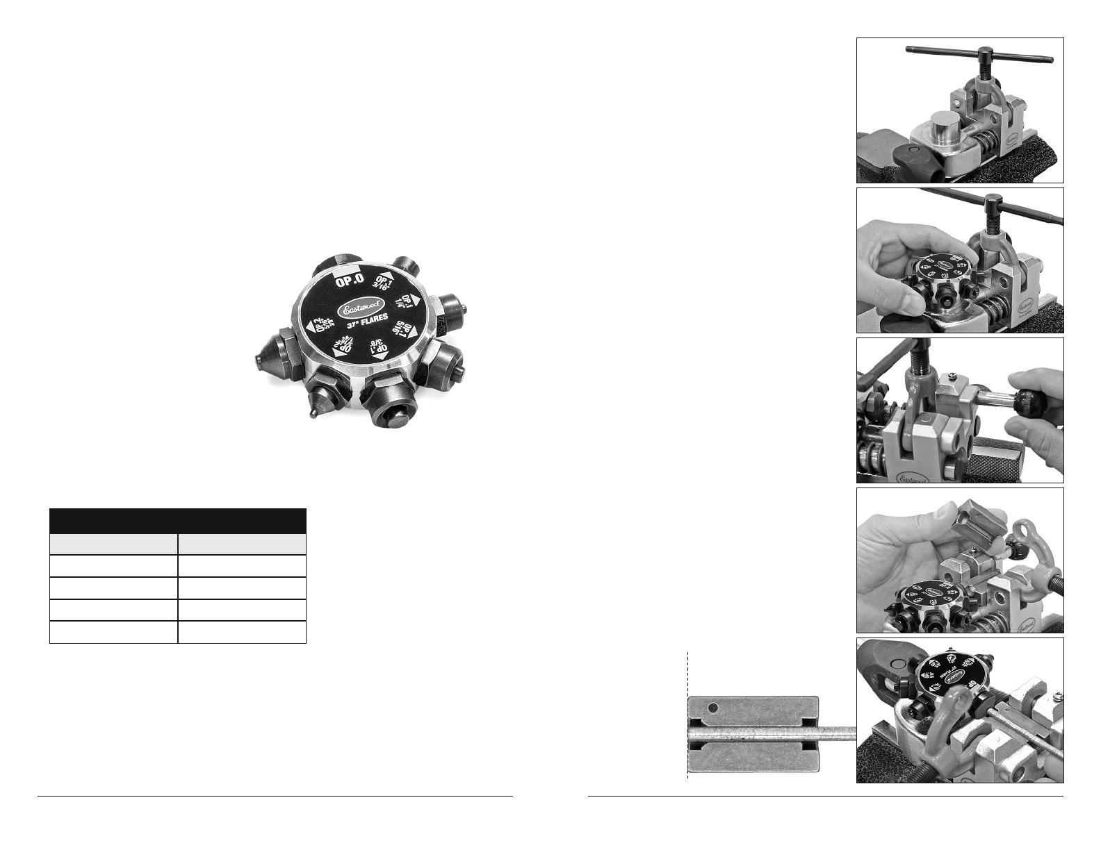
TOOL SET UP AND OPERATION
1. Place 1-1/2” x 1-1/2” square offset base of tool
(opposite the clamp) into a secure vise (Fig 1).
2. If the 45° / Brake Flare Die head is in place on
the tool, remove it by simply pulling up on the
block as it uses a ball detent to hold it in place.
Install the 37° Die Head onto the round boss.
Be sure to seat the Die Head fully and snap over
the ball detent (Fig 2).
3. Place 11” foam gripped handle into hole in lever
base. Be sure to seat handle fully and snap
groove into ball detent on side of hole.
4. Pull Clamp Pin (black knob) out
releasing clamp (Fig 3).
5. Rotate clamp upward.
6. Choose the split die size that matches the
tubing you will be fl aring. Insert the dies into
the rectangular recess in the tool base with the
sizes stamped on the die facing towards the
rotating Die Head and the back end fi rmly
against the step (Fig 4).
7. Place the tube between the die halves with the
tube end fl ush with the fl ared end of the dies.
The fl at faced OP.0 die is a gauge used to line
up the end of the tube fl ush with the split dies.
Rotate the Die Head so that the fl at faced OP.0
us facing the end of the tube. Move the lever
inward toward yourself until it stops and makes
the tubing fl ush with the split dies (Fig 5).
NOTE: The tube end MUST BE FLUSH with
the end of the die set to create a complete
double fl are (Fig 6).
AN to Fractional Conversion Chart
Tubing Size AN Size
3/16” -3
1/4” -4
5/16” -5
3/8” -6
PREPARING TUBING
1. Square cut the tube end. A tubing cutter works well for this.
2. Chamfer the outside and ream the inside of the tubing to remove any burrs.
Remove any metal chips from inside the tubing.
3. Wipe the exterior of the tubing clean to remove any metal chips.
4. Very lightly lubricate the end of the cut tubing with oil or anti seize compound.
5. Place appropriate fi ttings over the end of the tubing with the fl are end facing outward.
Tube end must be
fl ush with end of die
Fig. 1
Fig. 2
Fig. 3
Fig. 4
Fig. 6
Fig. 5